38 rc car wiring diagram
In this video Nick shows you how to wire your RC car for a clean factory look. He will be installing a Reedy ESC with all black 13awg wire and a shortened le... A width of ms generally sets the motor . Jul 08, · Learn about the basic components and wiring procedures for electric RC airplanes and helicopter powerplants. Easily connect your ESC and Brushless Motor to . Borders Model Boat Club Wiring Model Boats This article is intended to explain the basics of wiring a radio controlled model boats.
Right, can someone do a basic wiring diagram for a basic RC plane setup just to get it straight in my head. Lets say a 4ch setup, I cant fiqure out how to connect it all. Does motor require seperate battery or can I use the RX one. I really need to get of night shift so I can concentrate. Thanks, Lee.

Rc car wiring diagram
Rc car receiver wiring diagram wiring diagram is a simplified up to standard pictorial representation of an electrical circuit. The complete circuit diagram including the transmitter and receiver part for this project is shown in the images below. The servo slot is the ibus output from the receiver into which you will plug the servo wire coming ... Learn about the basic components and wiring procedures for electric RC airplanes and helicopter powerplants. Easily connect your ESC and Brushless Motor to ... Rc Car Wiring Diagram from i5.walmartimages.com Print the cabling diagram off in addition to use highlighters to trace the circuit. When you employ your finger or follow the circuit with your eyes, it is easy to mistrace the circuit.
Rc car wiring diagram. The process of converting an RC car to a Rover consists of adding an autopilot board in between the RC receiver and the ... _images/gps-wiring-diagram.jpg. Supplies needed: · 1) Wiring Diagram · 2) Completed Setup · 3) Close up of Control Board, Perf Board and Batteries mounted on wood · 4) Side view of mounted boards ... Table of Contents IP BRIDGE 4. RC-03 19. RC-04 3. IPB.PwrSup.LRReader IPB.PwrSup.Mag.REX.ExitButton.DSM 5. IPB.PwrSup.Mag.REX.ExitButton 6. IPB.PwrSup.Strike Dec 2, 2019 - Remote Control Circuit Diagram For Toy Car. ... Car Audio Amplifier · Electrical Wiring Diagram · House Wiring · Remote Control Cars.
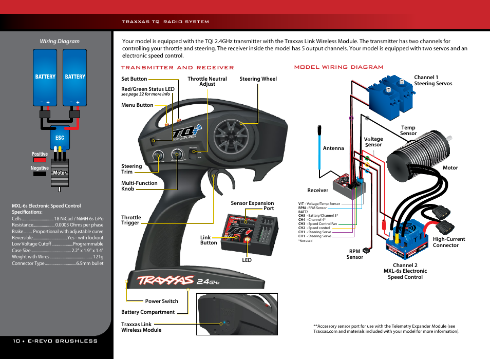
Having a remote start wiring diagram makes installing a remote starter easy. Find the remote starter wiring diagram you need to install your car starter and save time. Scroll down and find the car start wire guide you need. It's that easy! The best part? Every remote start wiring diagram contains information from other people […] Wiring Diagram WARNING This car is equipped with a remote control starting device. Disable before working on car! AVERTISSEMENT Co véhicule est équipé d'un systéme de démarrage á distance. Mettez-le hors fonctuin avant d'eflectuer toule opération d'entretian ou de répanation! Jt49rx61000 Rc Car Schematics Circuit Diagram Jada Toys. 12 18 24 Volt Single Battery Ride On Toy Wiring Diagram Kidswheels. Solved A Toy Car Contains An Electric Circuit With 10 000 Chegg Com. Circuit And Making Schema Alarm Led Speaker Remote Radio For Car. Tx049860 0401 Rc Car Schematics Circuit Diagram Silverlit Toys Manufactory. MODEL wIRInG DIAGRAM XL-5 Wiring Diagram The transmitter has two channels: Channel one operates the Motor steering, and channel two operates the throttle. 10% nitro blend is more economical for the sport user. 10% also • Top Fuel is the only fuel which is % certified for use in Traxxas engines.
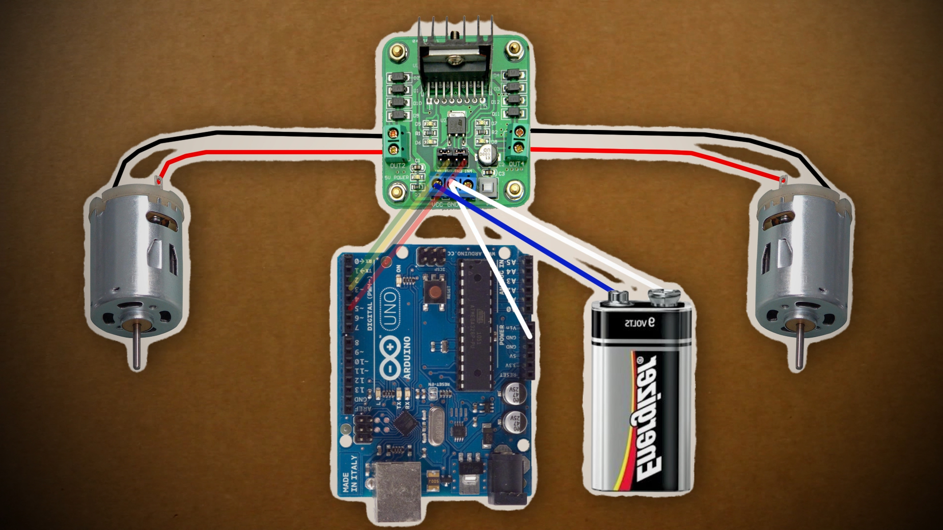
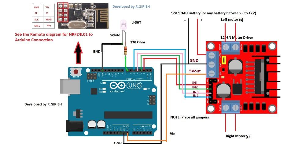
RC Car Circuit Diagram details for FCC ID PWYJT49RX61000 made by Jada Toys Company Limited. Document Includes Schematics Circuit Diagram. RC Battery Connectors. In the application of electric motors and batteries, connectors play a large role in transfering the battery power to the motor and through the ESC. Not only does it transfer power but it also must be able to break apart quickly for battery or motor replacements. This is my next project - Arduino 4WD RC Car with Joystick Controller or How easy it is to control an Arduino 4WD Smart Car with an analog Joystick. This RC joystick controlled car uses NRF24l01 as the transmitter and reciever. It has a range up to 1 kilometer in open space. ... Make connections as in the wiring diagram image above. This is the WLtech 10428-D RC Car. Electric toy car circuit diagram. The completed motor. SKIL Rechargeable 4V Cordless Screwdriver with Circuit Sensor Technology Includes 45pcs Bit Set USB Charging Cable Carrying Case - SD561204 46 out of 5 stars 4812 3499 34. A Determine the total resistance of the circuit.
2000 Ford E 350 electrical Wiring Diagram | Circuit Schematic learn
The RC car is a great project for all ages and it doesn't require any programming. It uses simple integrated circuits (IC) and it is controlled wirelessly by a remote controller. The remote controller sends out a encoded radio-frequency (RF) signal to the RC car. The RC car decodes the signal and moves accordingly.

white car crossing body of water
Learn about the basic components and wiring procedures for electric rc airplanes and helicopter powerplants. The following is a high level block diagram showing the data path through the system. Wi Fi Controlled Rc Car Using Esp8266 01 Andre Yuhai. Rc Car Wiring Schematic Wiring Diagram. 1 10 Rc Car Diagram Query.
30 Brushless Motor Wiring Diagram - Wiring Diagram Database
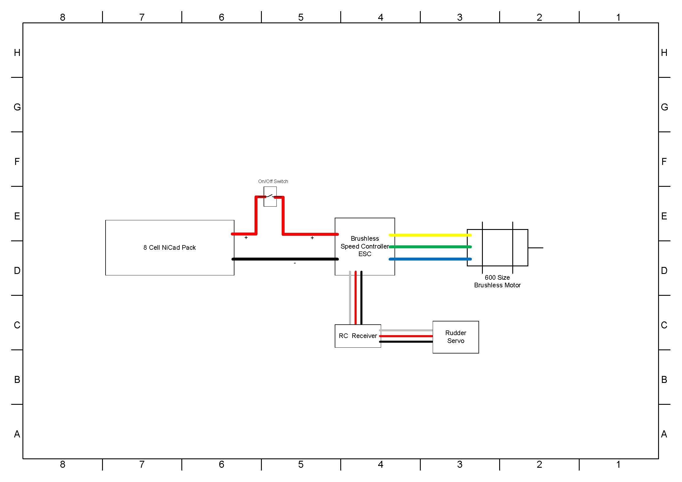
RC Model Wiring Diagram - Configuration 4b By Michael Best Jan 2011 LiPo (Rx) Medium-Large size model setup using dual BEC and batteries 6.0V 6.0V 5.5V ESC with BEC. THRO BA TT AILE-R ELEV R UDD AILE-L LiPo ESC BEC MOTOR RECIEVER SERVO SERVO SERVO SERVO Disconnect +V RC Model Wiring Diagram - Configuration 5
The Complete Guide to RC Electronics : 8 Steps (with Pictures) - Instructables
Most modern-day electric-powered radio control vehicles, whether airplanes, boats, or cars, have something built into their electronic speed controls (ESCs) that shunts power from the main battery to the receiver to power the radio system. This device is called a Battery Elimination Circuit — more commonly referred to simply as a BEC.

River City, Aerial Perspective (1979) // Bertrand Goldberg American, 1913–1997
circuit diagram app ipad new electrical wiring diagram software for wiring diagram par 32maa circuit. Block Diagram Vehicle theft detection engine locking project. We collect a lot of pictures about Remote Control Car Circuit Diagram Pdf. and finally we upload it on our website.

wellye Child electric car DIY accessories wires RECEIVER REMOTE controller toy car full set of ...
Rc Receiver Wiring Diagram from static-cdn.imageservice.cloud Print the wiring diagram off and use highlighters to be able to trace the circuit. When you make use of your finger or follow the circuit together with your eyes, it may be easy to mistrace the circuit. 1 trick that We use is to print a similar wiring diagram off twice.

33 Rc Car Diagram - Wiring Diagram Database
Jan 19, 2016 - Remote Controlled DC Motor for Toy Car Circuit Diagram Gallery of ... Sony Led, Electronic Schematics, Remote Control Cars, Circuit Diagram, ...

Marina City Theater, Chicago, Illinois, Roof and Partial Concrete Frame Development Drawing (1961-1962) // Bertrand Goldberg American, 1913-1997
April 5, 2017. 52805. Make any battery-operated toy car remote controlled using this circuit. This remote controlled toy car circuit, consisting of an infrared transmitter-receiver pair, uses IR beam transmission to switch the toy car 'on' or 'off '. To operate the toy car, you need to hold the transmitter in your hand, keeping it ...

Circuit 12v Ride On Car Wiring Diagram - madcomics
PDF Automotive Wiring Diagrams. The standard labeling system will use the first letter to indicate the base color, and the second letter to indicate the stripe color. An example would be the letters OB. This represents an orange colored wire with a black tracer stripe. RB is red with a black tracer.
RC Car Schematics
Rc Car Receiver Wiring Diagram - wiring diagram is a simplified up to standard pictorial representation of an electrical circuit. It shows the components of the circuit as simplified shapes, and the capacity and signal friends surrounded by the devices. A wiring diagram usually gives guidance about the relative viewpoint and promise of ...
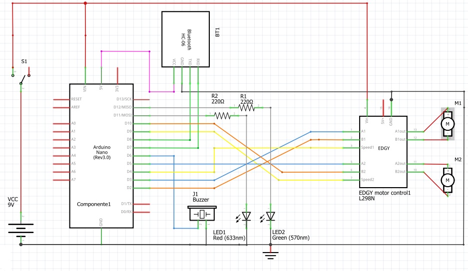
Wiring | Bluetooth RC Car Instructable
Jan 13, 2019 - We have so many collections wire wiring diagrams and schematics, possibly including what is you need, such as a discussion of the Anti Theft Alarm For Bikes Circuit Diagram. If the images produced less suitable way you can look for it using the search box.
RF Remote Control Car : 6 Steps (with Pictures) - Instructables
RC Car General Discussions - rc car circuit schematic - i have been searching the internet for a week to find a circuit schematic for a rc car. i dont want anything fancy, the most basic of basic wiring diagrams will do. it just needs to control 2 motors and have a range of maybe 30metres. i cant find a circuit

To Grow (1970) // Virginia Churchill Bath (American, active c. 1970) United States, Illinois, Beecher
When the crew at RC Car Action reviews a car, we follow the same steps while installing electronics to get a vehicle ready for photos. As with anything else in life, it will take some practice to learn and perfect anything. Though a Team Associated TC6.1 sedan was used for this article, the same concepts can be used when wiring up off-road ...
arduino | Tinkernut Labs | The Curious Mind Of A tinkerer
RC car remotes have a trigger and a knob to control different things. Most RC remotes have something next to the Control sticks called the trim. this basically slightly alters the position of your control sticks, and is useful for finely altering the position of the servos, or the starting point of a motor controller.
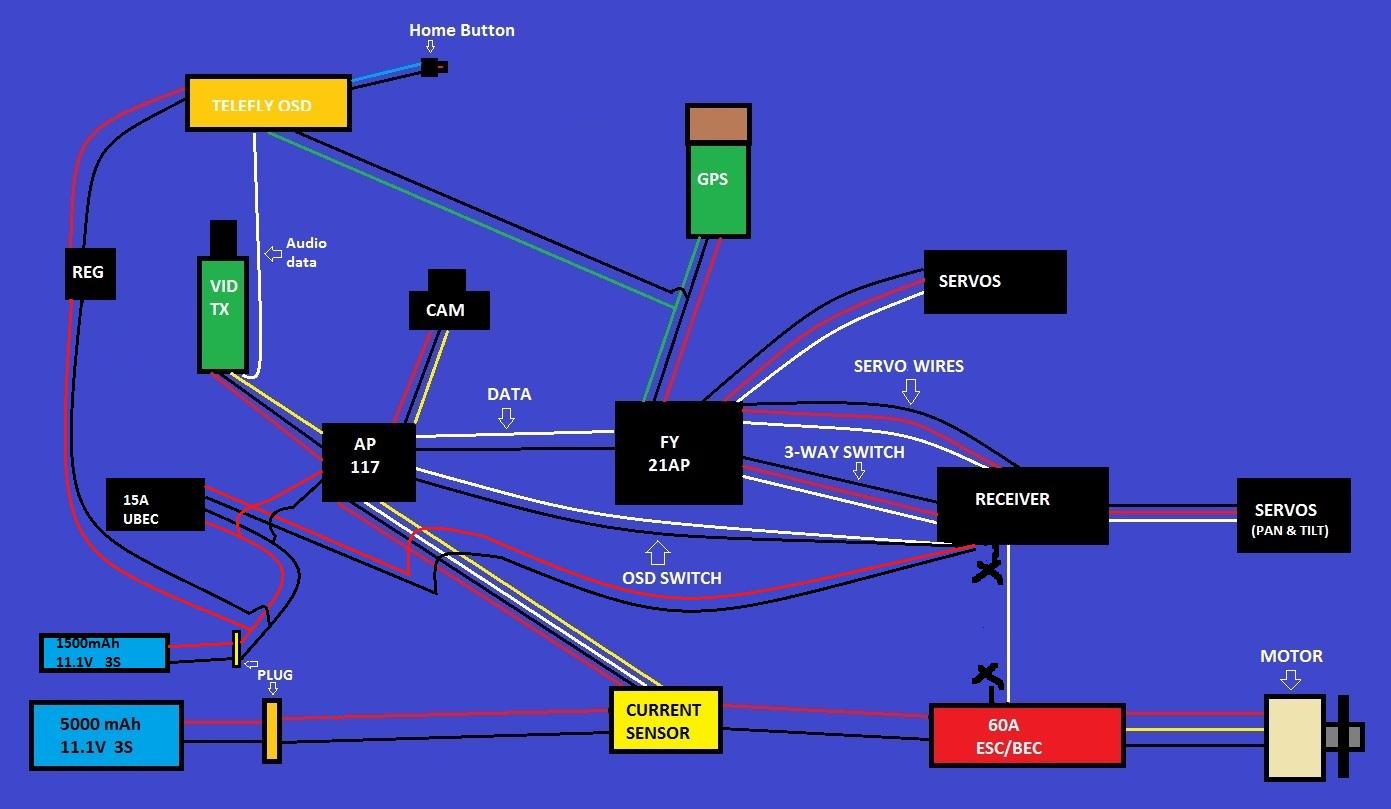
Attachment browser: Wiring Diagram FPV.jpg by khaled ...
www.cequentgroup.com ©2010 Cequent Performance Products, Inc. P/N 98929-2011 Rev. A. 11/10 for 2011 C-56 electrical W iri NG & acce SSO rie S WiriNG DiaGraMS 6-Way Molded Trailer/ sealed car connecTor & cable 6-Way Zinc die-casT connecTor

photography of wing mirror
Full Size of Car Diagram Rc Car Diagram Electric Wiring Diagramelectric Amazing s Electrical Circuit. We collect lots of pictures about Electric Rc Car Diagram. and finally we upload it on our website. Many good image inspirations on our internet are the most effective image selection for Electric Rc Car Diagram. .

Double check my work? - HeliFreak
Rc Car Wiring Diagram from i5.walmartimages.com Print the cabling diagram off in addition to use highlighters to trace the circuit. When you employ your finger or follow the circuit with your eyes, it is easy to mistrace the circuit.

closeup photo of black analog speedometer
Learn about the basic components and wiring procedures for electric RC airplanes and helicopter powerplants. Easily connect your ESC and Brushless Motor to ...

17+ Remote Car Starter Installation Wiring Diagram - Car ...
Rc car receiver wiring diagram wiring diagram is a simplified up to standard pictorial representation of an electrical circuit. The complete circuit diagram including the transmitter and receiver part for this project is shown in the images below. The servo slot is the ibus output from the receiver into which you will plug the servo wire coming ...
how to wire a nitro rc car - YouTube

Installation Diagram for Stone Line (c. 1976) // Richard Long English, born 1945
Renewing the Nikko Turbo 2 RC Car - Hackster.io
Bluetooth RC Car | Rc cars, Arduino, Car bluetooth
Hawg Wired
black car gps turned on in car
Traxxas Tqi Receiver With Oba Wiring Diagram
Is this BEC diagram correct? - RCU Forums

Make a Remote Controlled Toy Car Circuit ~ Electronic ...
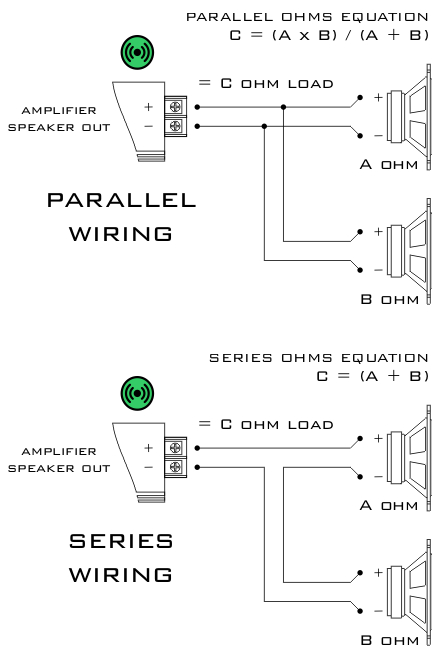
ESC Configurations | Boat wiring, Rc boats, Model airplanes

vintage orange car during daytime
Joystick Controlled 2.4 GHz RC Car Using Arduino ...

car headlight
Renewing the Nikko Turbo 2 RC Car - Arduino Project Hub
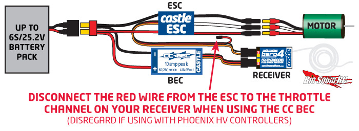
Everybody’s Scalin’ – Explaining the BEC « Big Squid RC – RC Car and Truck News, Reviews, Videos ...
Pololu - Wiring diagram for RC switch with medium low-side MOSFET.

River City II: Geometry Study (n.d.) // Bertrand Goldberg American, 1913-1997

time lapse photography of man riding car

blue vehicle parked near building at daytime


Comments
Post a Comment