40 sysml requirements diagram
SysML Requirements Parametric Modified from UML Same as UML [1] Modified UML Class Diagram [2] Enhanced UML Composite Structure Diagram SysML reuses many of the major diagram types of UML. In some cases, the UML diagrams are strictly re-used such as use case, sequence, state machine, and The SysML Requirements Model provides the system requirements, the expected abstract behavior and the operating constraints that the designed system must ...
A SysML requirement diagram enables you to visualize any kind of requirements of your system, both functinal and non-functional. You can also visualize the ...
Sysml requirements diagram
A SysML modelling element is placed on the diagram in order to graphically show traceability to stakeholder needs, requirements and test cases. See the Dependency path symbol for relationships that can be drawn on a req diagram. This SysML Diagram Tutorial is a Systems Modeling Language (SysML) primer that provides an overview of the nine (9) SysML diagram types and complementary Allocation Tables that constitute this de facto architecture modeling language standard for Model-Based Systems Engineering (MBSE) applications.. For a SysML primer that shows how SysML can be pragmatically applied to MBSE applications check ... Download scientific diagram | Example of a SysML requirement diagram. from publication: Model-Based Methodology for Requirements Traceability in Embedded Systems | We present a model-based ...
Sysml requirements diagram. SysML Diagram Types 15 Modified from UML New to SysML . Basic Features of SysML 16 . Source of the Diagrams •Lenny Delligatti - OCSMP AcceleratorTM SysML Training Course •DellSat-77 Satellite System Example 17 . ... Requirements Diagrams 22 Trace Relationship - You can also visualize the inter-relationships between requirements. By using SysML requirement diagram with UeXceler, you have a complete set of system requirements that involve the business goal, the user stories that describe user problems/concerns and the requirements to address the problems. Creating requirement diagram The SysML tool features a SysML requirement diagram tool that provides a visual approach in representing and managing system requirements. In a requirement diagram, requirements are shown as blocks, with connectors in between, illustrating the derivation, dependency and grouping of requirements. The requirement diagram tool allows you to define ... These requirement modeling constructs are intended to provide a bridge between traditional requirement management tools and other SysML models. Requirements diagrams display requirements, packages, other classifiers, test cases, rationales, and relationships.
I have read all tutorials and search for two days without finding any clues! my modelio version is 3.4.0 and the last sysml plugin. I am completely newbie in modelio utilisation and SysML. Thanks! What is a SysML Requirement diagram? Definitions. Requirement: A Requirement (notation: rectangle with «requirement» keyword) is a capability or condition that a system must ("shall") satisfy. A Functional Requirement (functionalRequirement» keyword) specifies a function that a system must perform, whereas a Non-Functional Requirement (NFR) specifies quality criteria that can be used to ... Research on the transformation of SysML Diagrams into OWL files is carried out by [18] and [7]. However, the transformation process in the research is still done manually. Research conducted by [18] uses several SysML diagrams, namely, requirements diagrams, activity diagrams, block 5.2 The structure of SysML diagrams Each diagram in the SysML has the same underlying structure, which is intended to provide a similar appearance for each, as well as making cross-referencing between diagrams simpler. The structure of each diagram is shown in Figure 5.2. The diagram in Figure 5.2 shows that each diagram is made up of one or
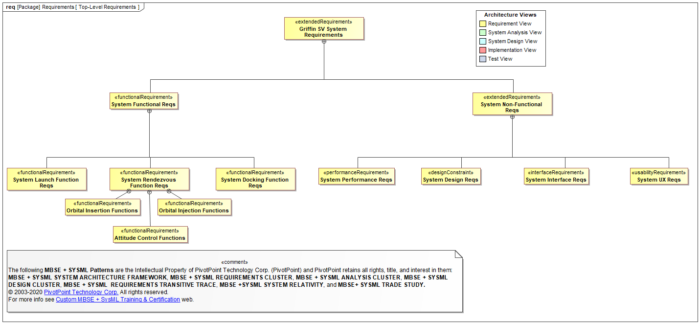
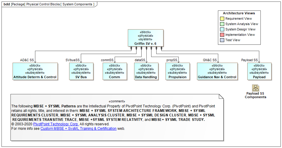
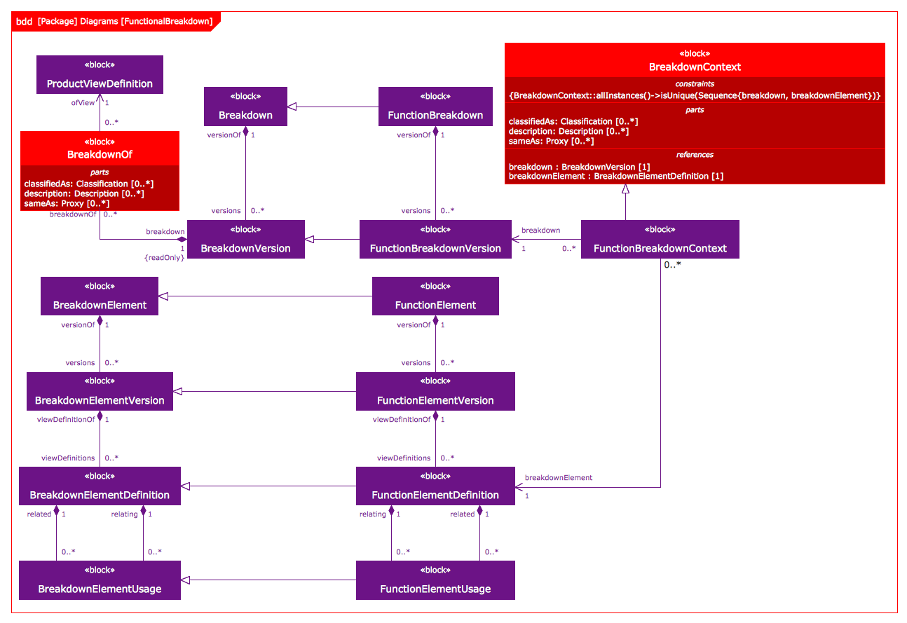
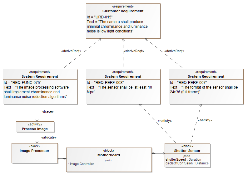
SysML Block Definition Diagram. Block Definition Diagram defines the features of a block and any relationships between blocks such as associations, generalizations, and dependencies, in terms of properties, operations, and relationships (for example, a system hierarchy or a system classification tree). Block Definition Diagrams are based on UML ... SysML provides modeling constructs to represent text-based requirements and relate them to other modeling elements. The requirements diagram can depict the requirements in graphical, tabular or tree structure format. A requirement can also appear on other diagrams to show its relationship to other modeling elements. SysML includes a graphical construct to represent text based requirements and relate them to other model elements. The requirements diagram captures requirements hierarchies and requirements derivation, and the satisfy and verify relationships allow a modeler to relate a requirement to a model element that satisfies or verifies the requirements. OMG SysML™ Requirements Traceability (informative) This document has been published as OMG document ptc/07-03-09 so it can be referenced by ... SysML Diagram Chapter Ver # 6.5 Mandatory Requirements 6.5.1 Structure N/A Structure diagrams include block definition, internal block,and package diagrams Structural
Modeling Requirements With Sysml Requirements Engineering Magazine
A SysML Requirement Diagram defines the requirements of a system. The SysML tool of VP Online is a web based diagramming tool, with a drag and drop interface to effortlessly create Requirement Diagrams. The SysML requirement tool comes with all the standard SysML notations you need to draw Requirement Diagrams.
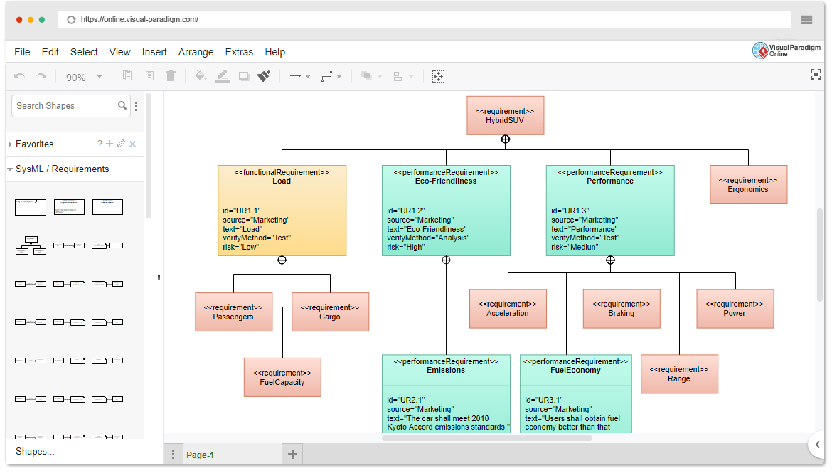
Free Sysml Requirement Diagram Tool
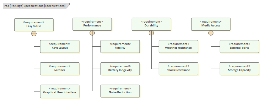
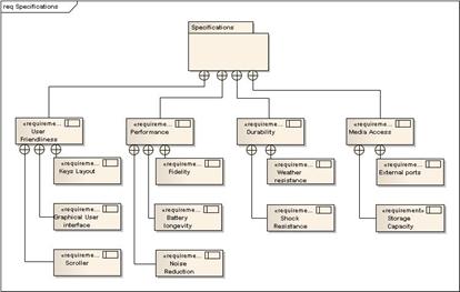
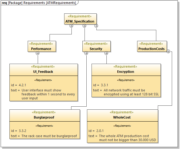
The SysML Requirements Model provides the system requirements, the expected abstract behavior and the operating constraints that the designed system must conform to. This diagram shows an example Requirements model for a Portable Audio Player. This example displays several top level Requirements such as 'Easy to Use' and then breaks those ...
Sysml Faq What Is A Requirement Diagram Req
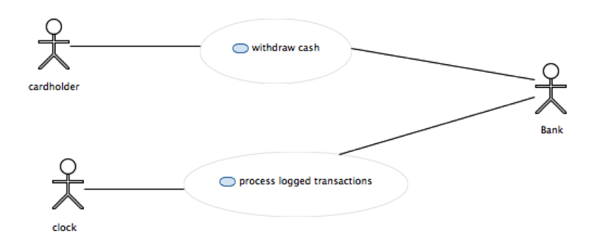
SysML: Identify User Requirements with Use Case Diagrams A Use case has been viewed as a mechanism to capture system requirements in terms of the uses of the system which specifies the expected behavior (what), and not the exact method of making it happens (how) of a system and thus, it is a black-box view of the system; it is therefore well ...
2
• SysML diagrams and language concepts • How to apply SysML as part of a model based SE process • Basic considerations for transitioning to SysML This course is not. intended to make you a systems modeler! You must use. the language. Intended Audience: • Practicing Systems Engineers interested in system modeling

Sysml Requirements Diagram Real Time Data Collection Viewpoint Download Scientific Diagram
An example of a SysML Requirements diagram. This diagram illustrates the breakdown of the Distiller's top level requirements into a hierarchy of more refined requirements. Learn more: Requirements Diagram. Prev : Next share this page share by email share on linkedin share on twitter share on facebook.
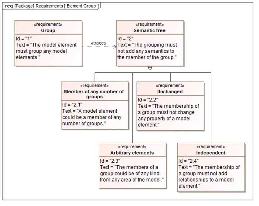
What S New In Sysml 1 4 Grouping Of Elements Model Based Systems Engineering
Functional requirements about the system under development are the most important input in creating a functional architecture. To identify and specify them, there are different methods, whose choice is independent of the intention of creating a functional architecture. Find a procedure for describing requirements in SysML in [Wei08].

Sysml Requirement Diagram For Production Reconfiguration Download Scientific Diagram
SysML Requirements diagram of the airbag con- trol system is depicted in Fig. 1. SysML also al- lows the representation of requirements, their proper- ties and relationships in a tabular format.
2
SysML provides modeling constructs to represent text-based requirements and relate them to other modeling elements. The requirements diagram can depict the requirements in graphical, tabular or tree structure format. A requirement can also appear on other diagrams to show its relationship to other modeling elements.

Mbse Sysml Example Nist Cyber Requirements
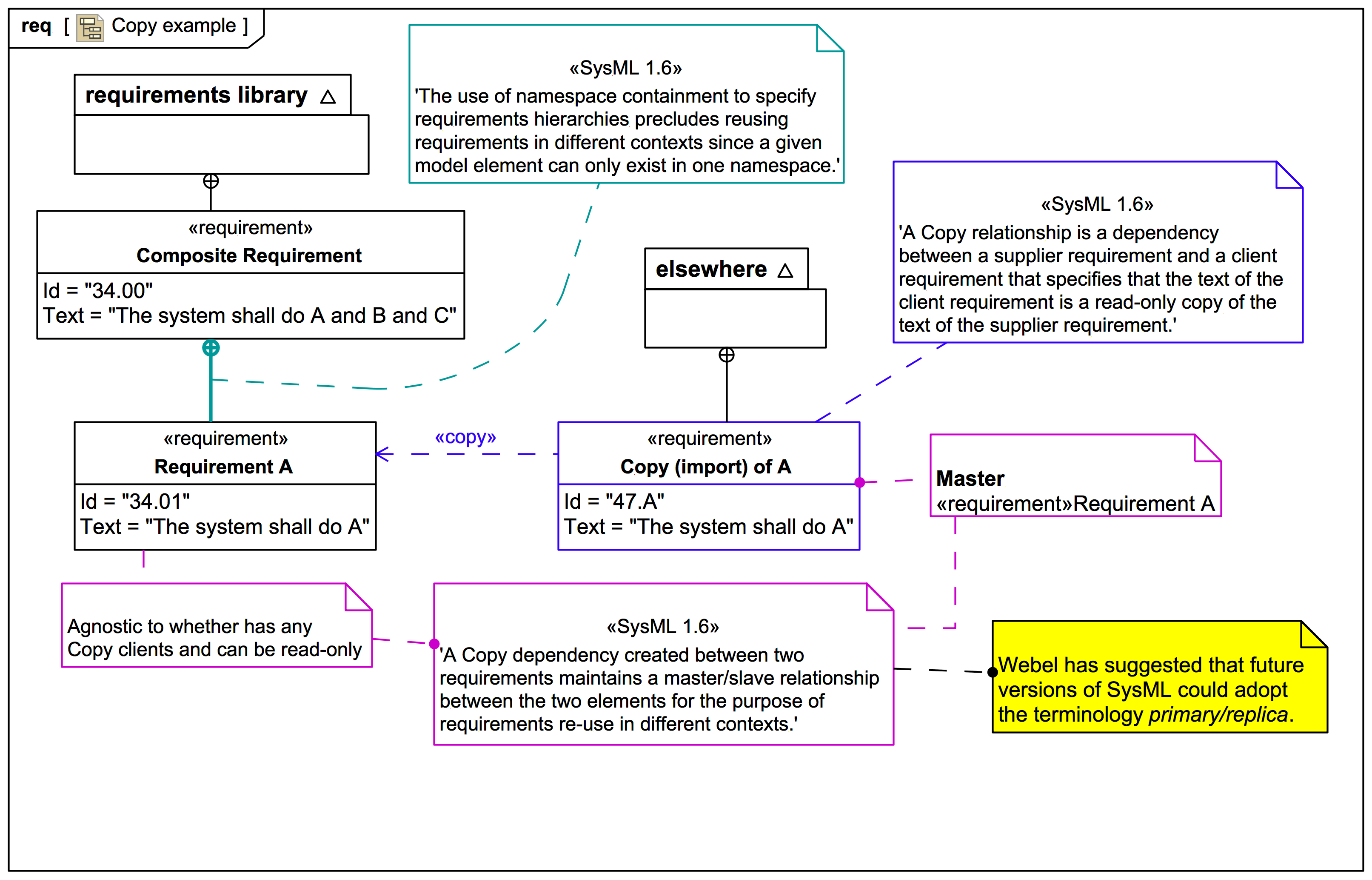
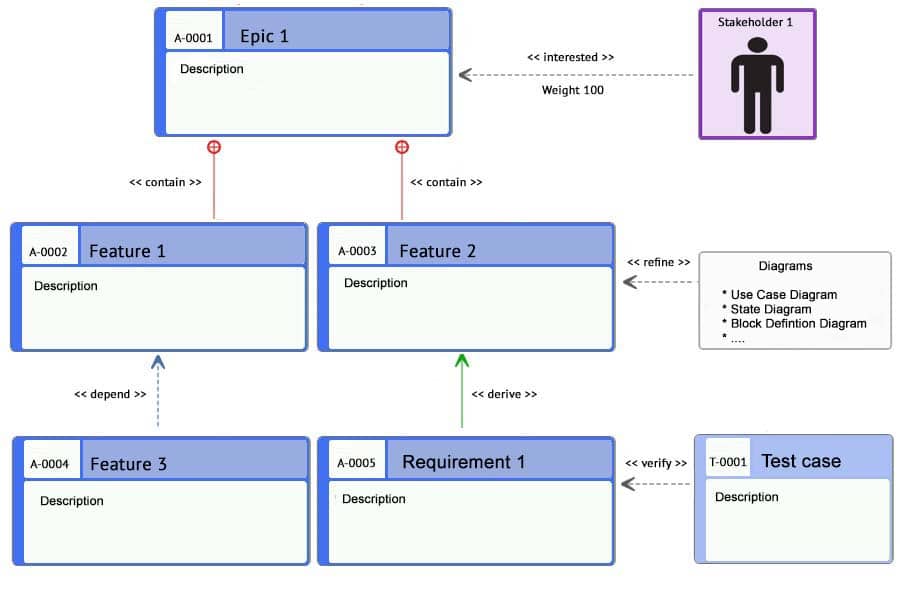
A requirement diagram is a diagram meant to show sets of requirements and their relations. SysML added the new Requirement stereotype and new kinds of relationship «contain», «refine», «satisfy», «allocate», and «verify». I use requirement diagrams sparingly but I do put requirements on other diagrams quite a bit.

Formal Modelling Of Seriot Requirements Seriot
On a diagram, you can create a SysML callout to list items or Requirements that are linked through the «satisfy» relationship: • For a Requirement, you can create a callout that lists the items that satisfy that Requirement - right-click the Requirement, point to Add, click Callout Note, and then select the satisfiedBy check box.
Step 3 Refine System Requirements Through A Sysml Model Eclipsepedia
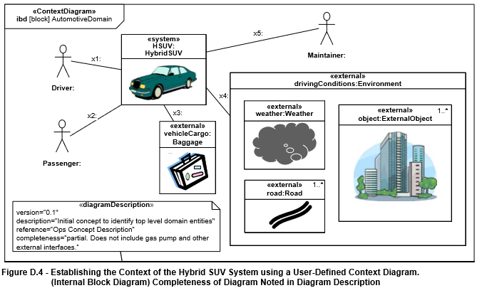
SysML Diagram Frames Each SysML Diagram must have a diagram frame Each SysML diagram frame represents a model element Diagram context is indicated in the header: Diagram kind (act, bdd, ibd, sd, etc.) Model element type (package, block, activity, etc.) Model element name User defined diagram name or view name
Sysml Requirement Diagram Webel It Australia
SysML predefines the following stereotype specializations of NFRs: Requirement diagram (req): A SysML Requirement diagram is a static structural diagram that shows the relationships among Requirement («requirement») constructs, model elements that Satisfy («satisfy» Dependency) them, and Test Cases that Verify («verify» Dependency) them.
1
Download scientific diagram | Example of a SysML requirement diagram. from publication: Model-Based Methodology for Requirements Traceability in Embedded Systems | We present a model-based ...
2
This SysML Diagram Tutorial is a Systems Modeling Language (SysML) primer that provides an overview of the nine (9) SysML diagram types and complementary Allocation Tables that constitute this de facto architecture modeling language standard for Model-Based Systems Engineering (MBSE) applications.. For a SysML primer that shows how SysML can be pragmatically applied to MBSE applications check ...

Easy To Use Sysml Modeling Software
A SysML modelling element is placed on the diagram in order to graphically show traceability to stakeholder needs, requirements and test cases. See the Dependency path symbol for relationships that can be drawn on a req diagram.
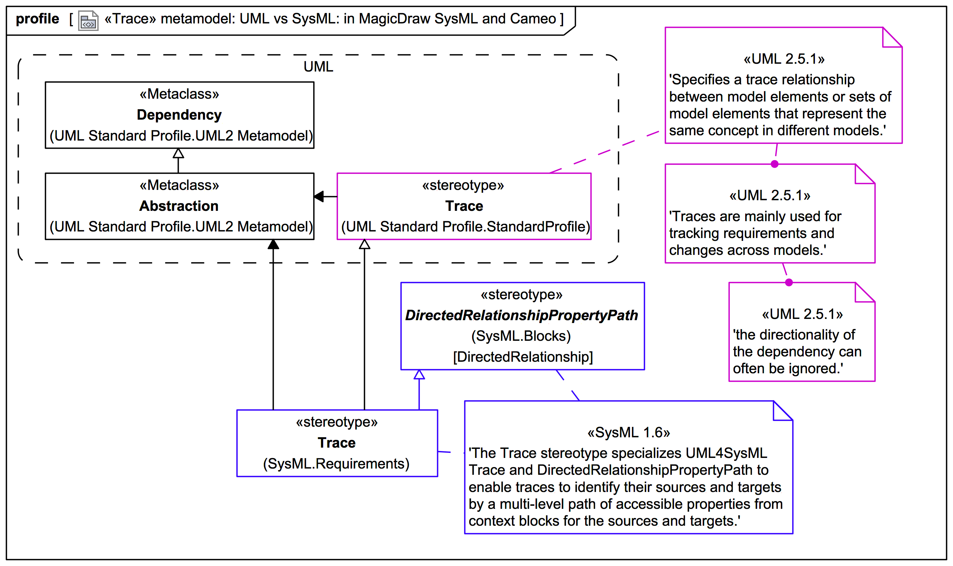
Requirements And The Trace Relationship Metamodel Webel It Australia
1
Sysml Diagram Tutorial Sysml Org

Systems Modeling Language Wikipedia
2
Sysml Solution Conceptdraw Com

Example Of A Sysml Requirements Diagram Download Scientific Diagram
A Sysml Requirements Model Enterprise Architect User Guide

Sysml Requirement Diagram Example For A Content Management System Cms This Requirement Diagram Example I Content Management System Paradigm Software Design

Diagrams Ownership
What Is A Requirement Diagram Smartpedia T2informatik
Sysml Foundations And Diagrams Springerlink
An Overview Of The Systems Modeling Language For Products And Systems Development

Requirement Diagram An Overview Sciencedirect Topics

Sysml Requirements Diagram And Dependencies Download Scientific Diagram
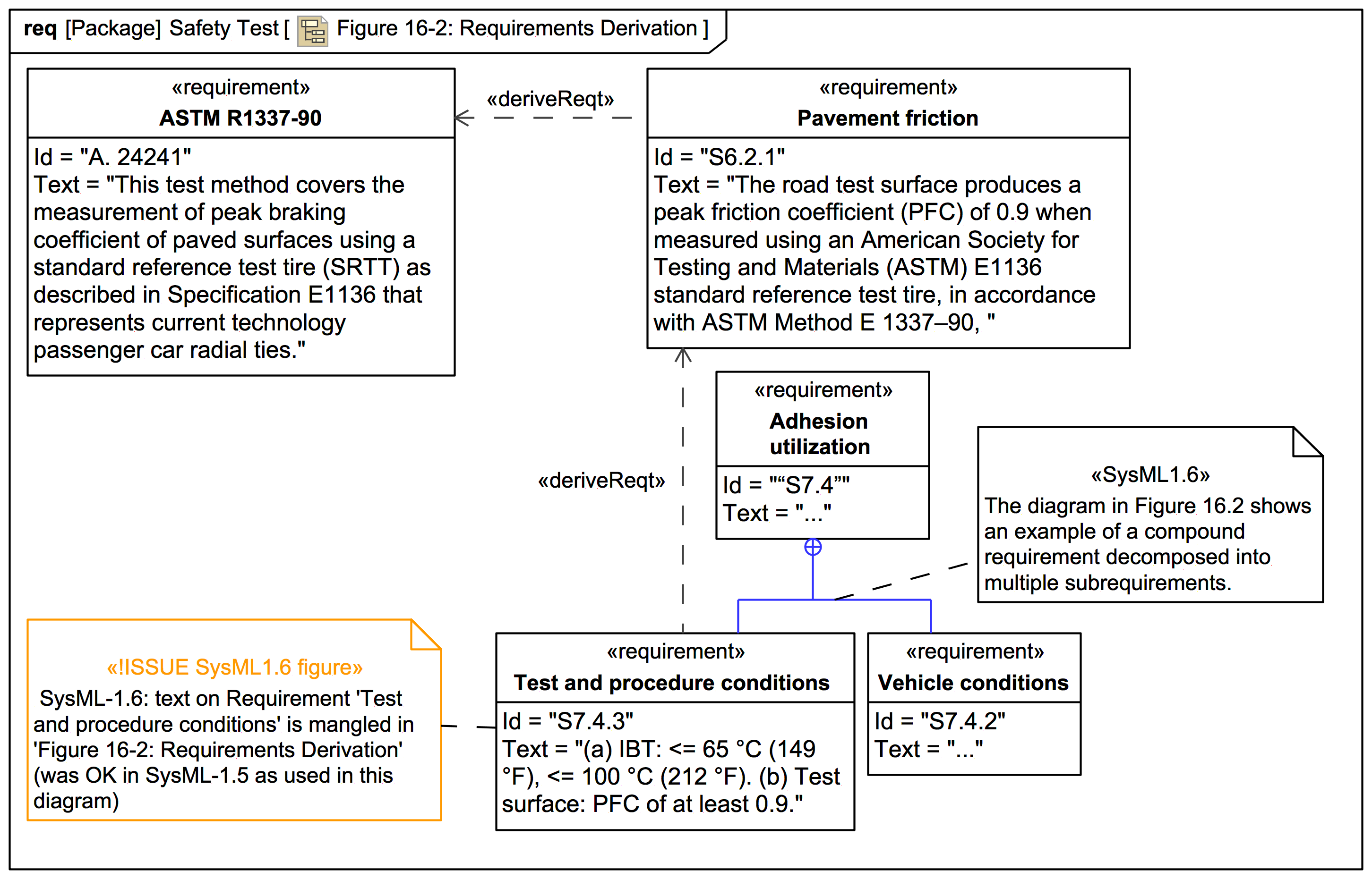
Figure 16 2 Requirements Derivation Webel It Australia

Requirement Diagram Innoslate Help Center
Sysml Faq What Is A Requirement Diagram Req
Iconix Iconix Process For Embedded Systems
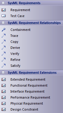
Sysml Requirements Toolbox Enterprise Architect User Guide
Functional

Thirteen Years Of Sysml A Systematic Mapping Study Springerlink
Altova Umodel 2022 Professional Edition
Is Capella A Sysml Tool

Requirements Diagram


Comments
Post a Comment