41 pressure enthalpy diagram water
Department of Energy Fundamentals Handbook THERMODYNAMICS, HEAT TRANSFER, AND FLUID FLOW Module 1 Thermodynamics Table A-5 Saturated water—Pressure table Table A-6 Superheated water Table A-7 Compressed liquid water Table A-8 Saturated ice-water vapor Figure A-9 T-s diagram for water ... Table A-26 Enthalpy of formation, Gibbs function of formation, and absolute entropy at 25°C, 1 atm
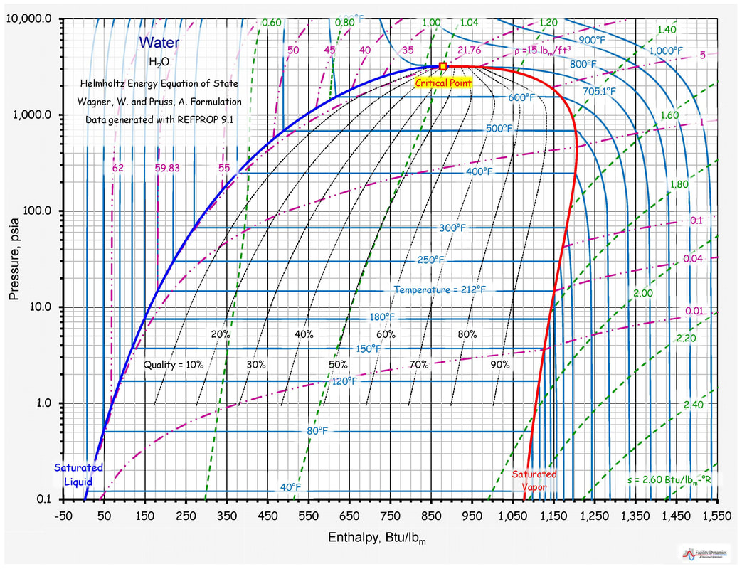
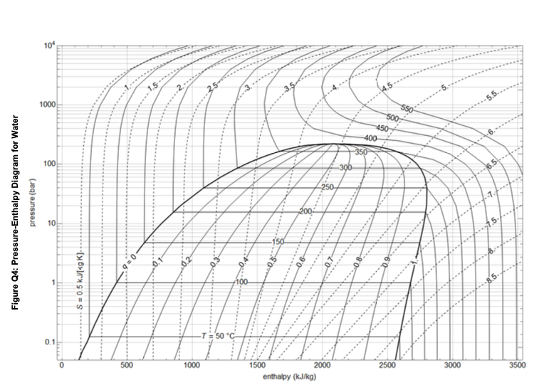
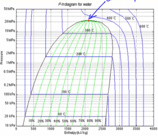
Pressure-Enthalpy Diagram for Water

Pressure enthalpy diagram water
2.1. Vapor Pressure 4 2.2. Thermal Conductivity 5 - Liquid - Vapor 2.3. Surface Tension 7 2.4. Viscosity 8 - Liquid - Vapor 2.5. Heat Capacity at constant pressure 10 - Liquid - Vapor 2.6. Enthalpy of Vaporization 12 2.7. Furfural-Water 13 - Solution-Temperature diagram - Vapor-Liquid composition • Table A–4: Saturation properties of water under temperature. • Table A–5: Saturation properties of water under pressure. A partial list of Table A–4. Enthalpy of vaporization, h fg (Latent heat of vaporization): The amount of energy needed to vaporize a unit mass of saturated liquid at a given temperature or pressure. Thermodynamic diagrams are very useful tools for folks working in the HVAC industry. The psychrometric chart is probably the most common. But if you find yourself working with steam, the pressure enthalpy diagram for water, the pressure-enthalpy diagram illustrated below, or the temperature-entropy diagram illustrated to the left, or the entropy-enthalpy diagram (or Mollier diagram ...
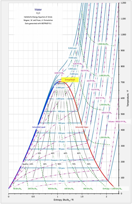
Pressure enthalpy diagram water. The following thermodynamic properties are calculated: density water, dynamic viscosity water, kinematic viscosity water, specific inner energy water, specific enthalpy water, specific entropy water, specific isobar heat capacity cp water, specific isochor heat capacity cv water, thermic conductivity water, speed of sound water. Saturation Properties - Pressure Table. Superheated Vapor Properties. Compressed Liquid Water Properties. Source of data: NIST Chemistry WebBook - accessed Jan 2008. Steam Property Diagrams: Pressure-Enthalpy Diagram. Enthalpy-Entropy Diagram _____ In refrigeration service work, gauge pressure (psig) is generally used. On a pressure-enthalpy diagram, however, the pressure is shown as absolute pressure (psia.) The difference between the two is about 14.7 pounds per square inch or about 30 inches of mercury (29.92 inches of mercury, to be more precise). Liquid Water - Properties at various Temperature and Pressure - Liquid water properties at temperatures between melting point and boiling point and pressures of 14.7 psia, 1000 psia and 10000 psia (1 atm, 68.1atm and 681 atm) Mollier Diagram for Water-Steam - Enthalpy-entropy diagram for water and steam
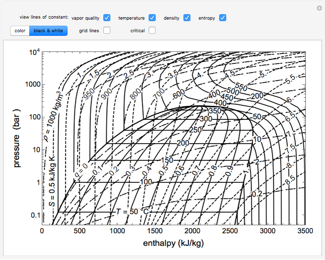
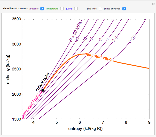
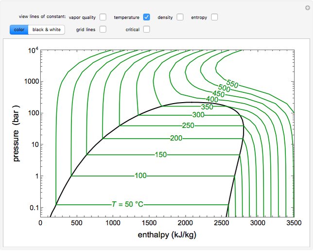
R718 (Water) Pressure Enthalpy Chart. Scroll down to find download buttons for pressure enthalpy charts in either Metric or Imperial Units. Downloads as a PDF. These charts were provided courtesy of Danfoss, using their FREE CoolSelector 2 software. Describes how to use an interactive simulation that represents a pressure-enthalpy diagram. The various sets of curves on the diagram (vapor quality, tempera... This Demonstration shows a pressure-enthalpy diagram for water.Check and uncheck the boxes to add or remove a property from the diagram. You can show lines of constant vapor quality (blue), temperature (green), density (orange, dashed) and entropy (purple, dashed). You can show grid lines using a checkbox. Enthalpy-Entropy Diagram For Water. This simulation shows an enthalpy-entropy (H-S) diagram for water. Use the checkboxes to display lines of constant pressure P (purple), temperature T (green) or vapor quality q (blue). Check "phase envelope" to show saturated liquid (magenta), saturated vapor (orange line) and the critical point (black dot).
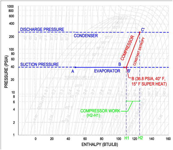
The pressure-enthalpy chart, as shown in Fig. 2, displays all the pertinent properties for a given refrigerant (in this example R22). The bubble to the left is the portion of the diagram where the refrigerant is in the saturated condition. The blue line on the left of the bubble represents the 100% saturated liquid line, Vapor Pressure and Enthalpy of Vaporization of Water Kyle Miller November 19, 2006 1 Purpose The purpose of this experiment is to calculate the enthalpy of vaporization of water by finding the vapor pressure of water over a range of temperatures. 2 Procedure In an inverted 10mL graduated cylinder, a sample of air is trapped. The cylinder is On the pressure-enthalpy diagram superheat is shown as horizontal movement along the suction pressure line passed the 100% vapor curve. The figure on the following page shows the difference between 0 °F and 15 °F superheat. Point B is the 100% vapor point at a constant evaporator/suction pressure of 36.8 psia and a temperature of 25 °F. Pressure-Enthalpy Diagram for Water and Steam Based on the IAPWS-95 Formulation for General and Scientific Use 10% 20% 30% 40% 50% 60% 70% 80% 90% Joule-Thomson Inversion 0.01 0.1 1 10 100 1000 10000 0 500 1000 1500 2000 2500 3000 3500 4000 4500 5000 Enthalpy, kJ/kg Pressure, bar

Pressure Enthalpy Diagram Property Diagrams And Steam Tables Assignment Help
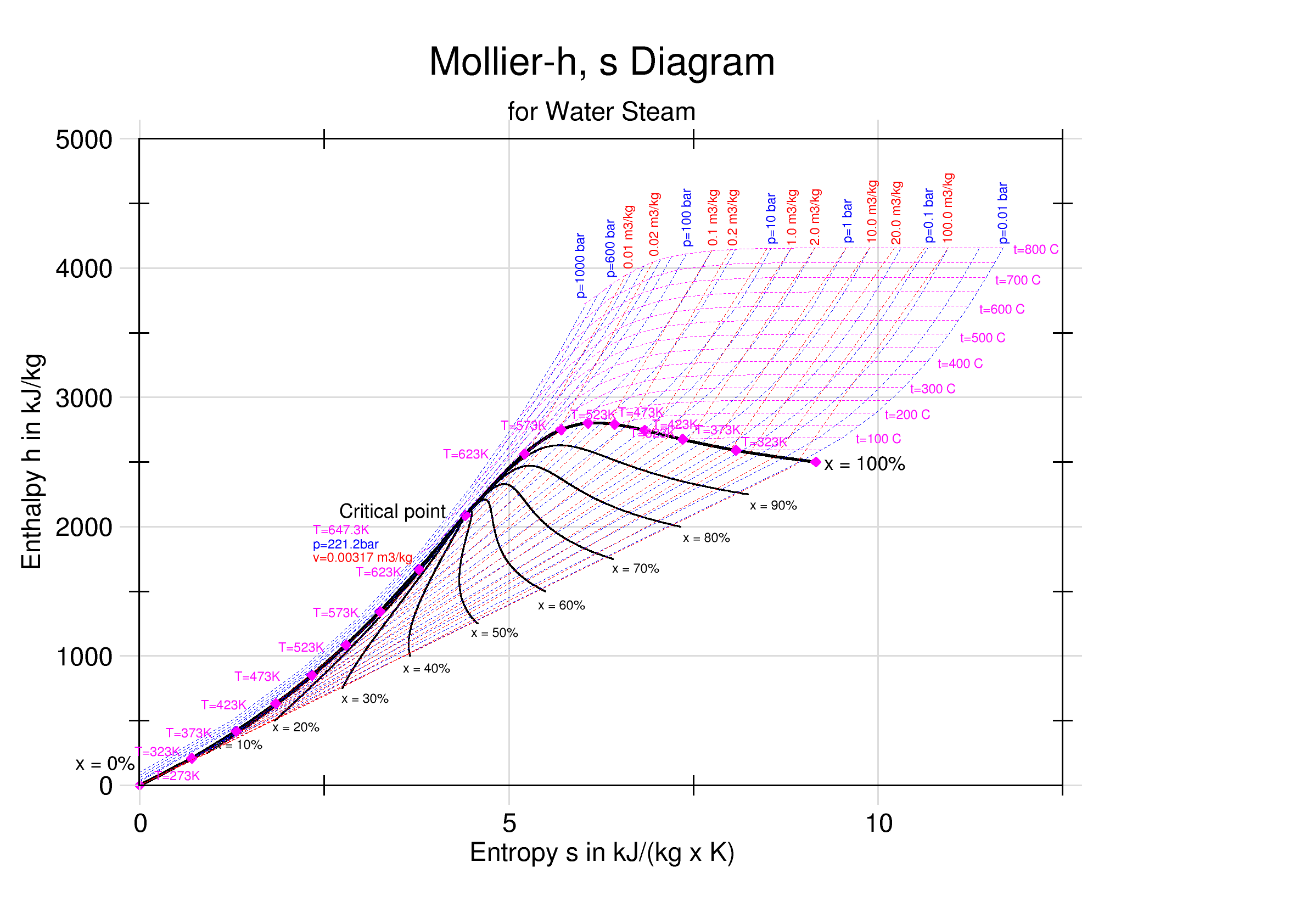
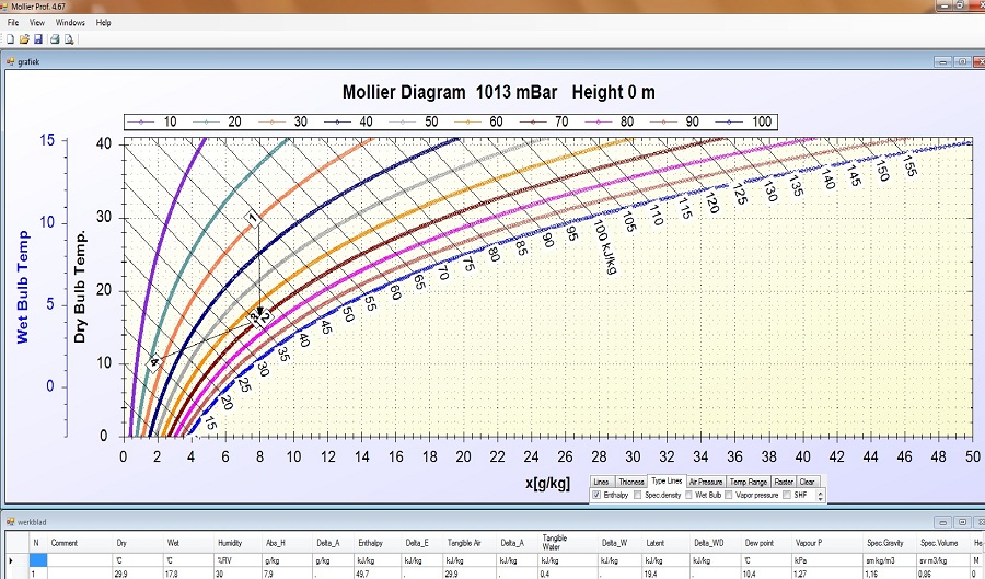
The diagram below can be used to determine enthalpy versus entropy of water and steam. Download and print Mollier Diagram for Water - Steam. The Mollier diagram is useful when analyzing the performance of adiabatic steady-flow processes, such as flow in nozzles, diffusers, turbines and compressors.
Mollier Diagram Pro Modelling And Simulation Software
WATER: PRESSURE-ENTHALPY DIAGRAM (Based on IAPWS-95 Formulation for General and Scientific Use) 200F 300F 400F 500F 600F 700 F 800F 800 F 1000F 1200F 100F 1500F s=1.0 s=1.5 s=2.0 s=1.6 s=1.7 s=1.8 v=1.0 v=5 v=10 v=2.5 v=0.5 v=0.3 v=0.1 s=1.1 v=40 v=20 900 F 900F 1300F 1400F s=1.2 s=1.3 s=1.4 s=1.9 s=2.1 s=2.2 s=2.3 s=2.4 s=2.5 s=2.6 s=2.7 s=2.8 50F 1100F v=0.15 v=0.2 v=60 v=80 v=100 v=200

Appendix D Pressure Enthalpy Diagrams For Various Compounds Chemical Engineering Fluid Mechanics 3rd Edition Book
Look at Figure 2, which shows the pressure-enthalpy diagram for water. As you can see, at a pressure of 15 psig (29.7 psia), water begins to boil at 253°F. At that pressure/temperature condition, the addition of 1,165 Btu of heat energy is required to change each pound of water to steam. At 0 psig (14.7 psia), water begins to boil at 212°F.

Pressure Enthalpy Diagram For Water
WATER: PRESSURE-ENTHALPY DIAGRAM (Based on IAPWS-95 Formulation for General and Scientific Use) 200F 300F 400F 500F 600F 700 F 800F 800 F 1000F 1200F 100F 1500F s=1.0 s=1.5 s=2.0 s=1.6 s=1.7 s=1.8 v=1.0 v=5 v=10 v=2.5 v=0.5 v=0.3 v=0.1 s=1.1 v=40 v=20 900 F 900F 1300F 1400F s=1.2 s=1.3 s=1.4 s=1.9 s=2.1 s=2.2 s=2.3 s=2.4 s=2.5 s=2.6 s=2.7 s=2.8 50F 1100F v=0.15 v=0.2 v=60 v=80 v=100 v=200
Thermodynamic Diagrams Spreadsheet
http://demonstrations.wolfram.com/PressureEnthalpyDiagramForWaterThe Wolfram Demonstrations Project contains thousands of free interactive visualizations, wi...
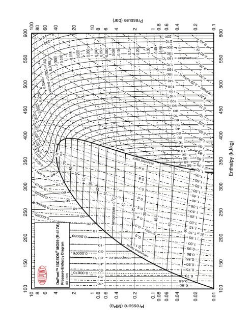
Pressure Enthalpy Diagram For Isceona Mo59 Si Dupont
WOLFRAM | DEMONSTRATIONS PROJECT. P r e s s u r e-E n t h a l p y D i a g r a m f o r W a t e r. v i e w l i n e s o f c o n s t a n t:
Pressure Enthalpy Diagram For Water Wolfram Demonstrations Project
3.3 Phase Diagram for Water Vapor: Clausius-Clapeyron Equation. The Clausius-Clapeyron Equation. We can derive the equation for e s using two concepts you may have heard of and will learn about later: entropy and Gibbs free energy, which we will not go into here.Instead, we will quote the result, which is called the Clausius-Clapeyron Equation,

Category Using Pressure Enthalpy Diagrams Fundamental Refrigeration
This Demonstration shows an enthalpy-entropy (-) diagram for water.Use the checkboxes to display lines of constant pressure (purple), temperature (green) or vapor quality (blue). Check "phase envelope" to show saturated liquid (magenta), saturated vapor (orange line) and the critical point (black dot).

Pressure Enthalpy Diagram For Pure Water Showing Contours Of Equal Download Scientific Diagram
the water temperature vs. the enthalpy of the water (heat con-tent in Btu/lb). We all know that water boils at 212ºF (atmos-pheric pressure at sea level). By definition, water at atmospher-ic pressure, at a temperature lower than 212ºF, is subcooled. So, we start with subcooled water at 42ºF, and begin transfer-ring heat to it.

Category Using Pressure Enthalpy Diagrams Fundamental Refrigeration
This screencast has been updated. Please see the revised version here: https://youtu.be/jGIHNKLMLCY Made by faculty at the University of Colorado Boulder, D...
Enthalpy Entropy Chart Wikipedia
This video explains the parts of a pressure-enthalpy diagram for a single-component system and discusses how enthalpy depends on pressure for water. If these diagrams are a breeze for you, or you're just looking for help with another concept, check out other chemical engineering tutorials in the Learn ChemE Engineering Screencast series .
2
Enthalpy of dry saturated steam . Hs = Liquid enthalpy + Enthalpy of evaporation. i.e., Hs = h + L kJ/kg. Enthalpy of dry saturated steam is the quantity of heat required to convert 1 kg water at 0°C into dry saturated steam at constant pressure. Enthalpy of wet steam, H's = h+ qL kJ/kg . Enthalpy of superheated steam,
Enthalpy Entropy Diagram For Water Wolfram Demonstrations Project
Thermodynamic diagrams are very useful tools for folks working in the HVAC industry. The psychrometric chart is probably the most common. But if you find yourself working with steam, the pressure enthalpy diagram for water, the pressure-enthalpy diagram illustrated below, or the temperature-entropy diagram illustrated to the left, or the entropy-enthalpy diagram (or Mollier diagram ...
1
• Table A–4: Saturation properties of water under temperature. • Table A–5: Saturation properties of water under pressure. A partial list of Table A–4. Enthalpy of vaporization, h fg (Latent heat of vaporization): The amount of energy needed to vaporize a unit mass of saturated liquid at a given temperature or pressure.
Solved A Power Generation Cycle Uses Water As The Working Chegg Com
2.1. Vapor Pressure 4 2.2. Thermal Conductivity 5 - Liquid - Vapor 2.3. Surface Tension 7 2.4. Viscosity 8 - Liquid - Vapor 2.5. Heat Capacity at constant pressure 10 - Liquid - Vapor 2.6. Enthalpy of Vaporization 12 2.7. Furfural-Water 13 - Solution-Temperature diagram - Vapor-Liquid composition

Pressure Enthalpy Diagram For Water Interactive Simulation Youtube

Pdf Pressure Enthalpy Diagram For Water And Steam Based On The Iapws 95 Formulation For General And Scientific Use 10 20 30 40 50 60 70 80 90 Joule Thomson Inversion Fabricio Bez Academia Edu
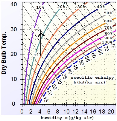
Moist Air The Mollier Diagram
Thermodynamic Diagrams Spreadsheet
Reading Thermodynamic Diagrams

File Pressure Enthalpy Chart For Steam In Us Units Svg Wikimedia Commons

Saturated Multi Phase Systems And Proof That A Watched Pot Does Actually Boil Part 1 A Field Perspective On Engineering

The Latent Heat Of Climate Change Redux Manuelgarciajr
2
Enthalpy Entropy Chart Wikipedia
Mollier Diagram Pro Modelling And Simulation Software
Tutorial Pressure Enthalpy Diagrams Aiche

Pressure Enthalpy Diagram Example Hvac School

Chapter 8a Ideal Rankine And Reheat Steam Power Cycles Revised 4 25 10

Pressure Enthalpy Chart

Pressure Enthalpy Charts Industrial Controls
Using Mollier S Chart What Is The Final Pressure And Temperature Of Steam When It Is Isentropically Expanded From Enthalpy Of 3500 Kj Kg And 30 Bar Pressure To Enthalps Of 2900 Kj Kg Quora
P H Diagram Thermodynamics Hvac And Refrigeration Pe Exam Tools Mechanical And Electrical Pe Sample Exams Technical Study Guides And Tools

Phtchart Maple Help

Pressure Enthalpy Diagram For Pure Water Fournier 1999 For Download Scientific Diagram

Pressure Enthalpy Diagram For Water And An Orc Fluid Butane Download Scientific Diagram
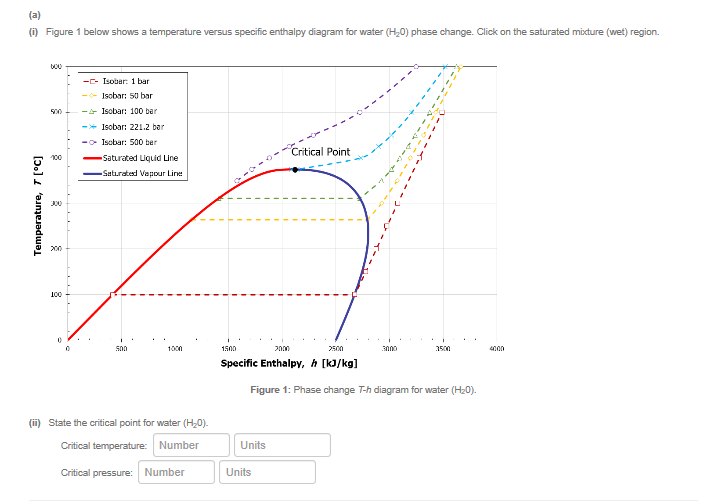
Solved 0 Figure 1 Below Shows A Temperature Versus Specific Chegg Com
Pressure Enthalpy Diagram For Water Wolfram Demonstrations Project
4 Pressure Enthalpy Diagram The Operating Condition Of Vcc The Download Scientific Diagram
2

Pressure Enthalpy Diagram Of The Refrigeration Cycle Refrigeration And Air Conditioning Hvac Repair Hvac Filters


Comments
Post a Comment