43 diagram of lift
Working principle diagram of lift check valve. Lifting check valve is a kind of valve that prevents pipeline media from flowing back, mainly composed of valve body, valve seat, valve flap, valve cover and other related parts. The lift check valve is equipped with a spring to ensure that the disc is always in a dynamic equilibrium state under ... 1.2.2 Installation manual, general structural diagram of the elevator, mechanical installation drawings, packing list, electrical installation and wiring diagrams, electrical schematic diagrams, commissioning, operating, and maintenance guides, etc. 1.2.3 Installation and acceptance data of the elevator, relevant standards, and
diameter, larger pitch, and more blades would generate larger lift force. For Test 2, the wind shield, with larger area and smaller distance under the propeller, would increase the propeller lift force. For Test 3, more unbalance of the propeller would result in larger vibration. However, it is difficult to well quantify the unbalance.

Diagram of lift
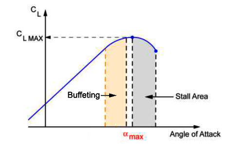
experience the sensation of lift. The instructor will present information about airfoil design, lift, and the Bernoulli Principle for all participants, but those in the 5th - 12th grades may engage in a brief discussion about the Area Rule and the difference between laminar flow airfoils and conventional airfoils. Objectives . Students will: 1. The [second figure] provides supplementary information to illustrate the significance of the V-n diagram [shown earlier]. The lines of maximum lift capability are the first points of importance on the V-n diagram. The subject aircraft is capable of developing no more than one positive "g" at 100 knots, the wing level stall speed of the airplane. Lift is the key aerodynamic force that keeps objects in the air. It is the force that opposes weight; thus, lift helps to keep an aircraft in the air. Weight is the force that works vertically by pulling all objects, including aircraft, toward the center of the Earth. In order to fly an aircraft, something (lift) needs to press it in the opposite
Diagram of lift. Crane dimensions and area (quadrant) of operation diagram Provide copy of annual 3 rd party inspection certification and report - see Crane Lift Plan for requirements (Note: The inspector shall be certified with the CCAA - see www.CCAAweb.net local resources) Scaled site plan and elevation drawings Spinning blades push air down. Of course, all forces come in pairs, which means that as the rotor pushes down on the air, the air pushes up on the rotor. This is the basic idea behind lift, which ... 220v Car Lift Wiring Diagram - wiring diagram is a simplified tolerable pictorial representation of an electrical circuit. It shows the components of the circuit as simplified shapes, and the skill and signal links in the middle of the devices. A wiring diagram usually gives guidance nearly the relative turn and contract of devices and ... The forklift lift cylinder powers the vertical movement of the mast, or the raising or lowering of the forklift carriage and the forks. The lift cylinder is generally hydraulically powered and is a single-acting hydraulic cylinder, meaning it pushes in one direction.
Lift system manual or diagram neede. 1990 Jayco 1006. Most do-it-yourselfers can repair Jayco camper cables with minimal. I am getting a Jayco Pop-up Camper. the Lifting crank mechanism needs repaired. The handle turns but it dont lift. Elevator features and operation may vary from one elevator to another. So, I will show the basic components for a standard type of elevators which included in all types of traction elevators. Type (I): starting from 320 Kg up to 800 Kg rated load. Type (II): more than 800 Kg up to 1600 Kg rated load. Arrangement (A): Car with side opening door ... Typical Lift Station Detail - One Line Diagram LS6 …. Typical Lift Station Detail - Plot Plan Layout . PREFACE These Sewer Lift Station Specifications and Drawings are intended to supplement the current edition of the Idaho Standards for Public Works Construction (ISPWC) and the City of Meridian Lift Chair Service Guide Models Included: This Service Guide contains: Troubleshooting Replacement Instructions Illustrated Parts Diagrams <Part Number>/01.01.09/Rev52
Lift is the force that directly opposes the weight of an airplane and holds the airplane in the air. Lift is generated by every part of the airplane, but most of the lift on a normal airliner is generated by the wings. Lift is a mechanical aerodynamic force produced by the motion of the airplane through the air. Because lift is a force, it is a vector quantity, having both a magnitude and a ... Assortment of 2 post lift wiring diagram. A wiring diagram is a streamlined standard pictorial depiction of an electrical circuit. It shows the parts of the circuit as streamlined forms, as well as the power as well as signal connections between the tools. 5 To improve the model validation, it is planned to get some other engine tests results, such as valve lift diagram , oil pressure at hydraulic actuator, etc. Motion synchronization for dual-cylinder electrohydraulic lift systems. The free-body diagram of A two-post hydraulic lift system is shown in Fig. 2. Lift System. Since 1976, Goshen Stamping has made the most popular lift system for pop-up tent campers in the industry. This system is easy to install, easy to maintain and easy to repair if necessary. Only one cable is used to operate the spring push system. This system can be operated with a hand crank winch or an approved motorized winch.
Lift Force Wikipedia
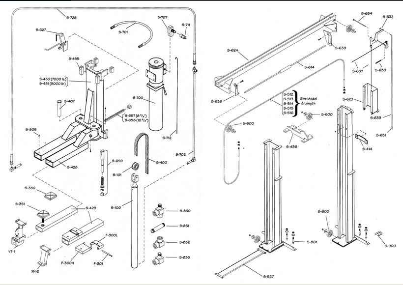
CONCRETE PAD INSTALLATION BILL OF MATERIALS. 1 One (1) Advance Model Number _____. 2 One (1) electric disconnect switch for 5 or 7-1/2HP motor. 3 One (1) plug receptacle. 4 Concrete anchor bolts and material for shimming and/or grouting. *Seller furnishes items 1 only unless otherwise agreed to in writing.
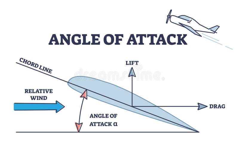
Angle Of Attack As Aerodynamic Physical Force Explanation Outline Diagram Stock Vector Illustration Of Physics Drag 226433326
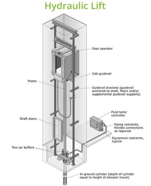
Lift cabin moves in this space. Depending upon the type of elevator, the location of the shaft can be varied. Doors. As normal doors, elevator doors are also meant for entry and exit. Elevator door is of two types: Manual doors and Automatic doors. Manual doors: These types of doors are opened with the help of a person who wants to enter the lift.

Apluslift Hw Sl6600x Mid Rise 6 600lb Auto Scissor Lift 110v Free Shi Apluslift Official Store
The difference in length of the arrows representing lift and weight in the diagram above represents the relative magnitudes of the forces of lift and weight acting on the aeroplane. The lift arrow is longer, therefore, the lift force is greater than the plane's weight and we can deduce that this plane is climbing so its altitude will increase.
Airfoils Bernoulli And Newton
Find below safe work lifting plan template for use in crane lifting process. This lifting plan sample also provides calculation for sling tension. Additionally you shall be able to select the suitable lifting gear in accordance with the safe working load and weather conditions etc. Once you will record the data you will get a…
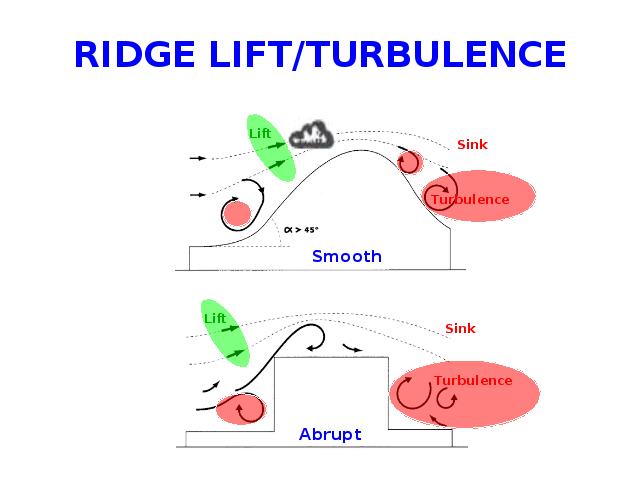
Ridge Lift Turbulence Diagram
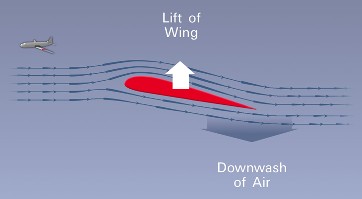
The explanation for lift has been traditionally attributed to a Swiss mathematician named Daniel Bernoulli (pronounced Ber-noo-lee). However, recently, many scientists have debated whether the use of the Bernoulli principle to explain how wings work is, in fact, correct.
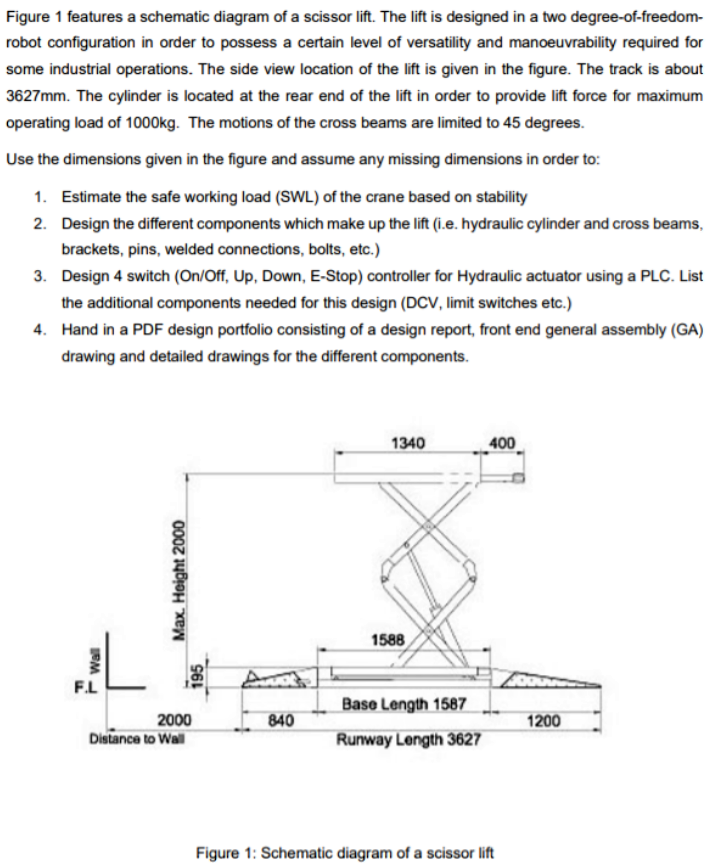
Figure 1 Features A Schematic Diagram Of A Scissor Chegg Com
actual use. See diagram 2 showing the patient in a comfortable seated position facing the attendant. Feet should rest on the base of the lift. Typical U-Sling diagram 1 Typical U-Sling diagram (Internet image) diagram 2 Visual of sling being used by patient Applying the Sling: • Roll patient so the are resting on their side.

Cheney Handi Lift Ii Installation Operation Service Manual And Wiring Diagram Download Cheney Access2parts Com
Pride Seat Lift Chair Recliner Hand NEW WIRING DIAGRAM. Manaufacture: Pride. Rotate the iTrip AutoPilot FM Transmitter controller so that its buttons are facing up and its data cable is on the left side. The data cable wires. chairs in this service manual, but some of them are specific to individual chairs.
Auto Lift Parts Stabilizer Cable Adjustment Diagram For Ben Pearson 2 Post Lifts Svi International Model Lift Parts Benpearson 2post Cables Automotive Equipment Distributors Automotive Tools And Equipment Auto Lift Equipment Hunter
Scissor lift Mechanism (i.e. four bar paralel mechanism) [3]. 2. Lift Mechanism and Geometry The complete system model of the scissor lift mechanism shown Figure1.The parts of this mechanisms are rampa, platform, scissor links, revolute and slider joints, hydraulic cylinder and base port. Techinical datas of lift mechanisms
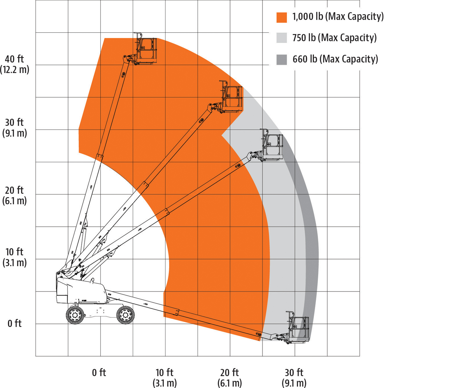
40 Ft Diesel Dual Fuel Telescopic Boom Lift For Rent Bigrentz
Lift is the component of this force that is perpendicular to the oncoming flow direction. It contrasts with the drag force, which is the component of the force parallel to the flow direction. Lift conventionally acts in an upward direction in order to counter the force of gravity, but it can act in any direction at right angles to the flow.

File Anderton Boat Lift Diagram 2 Png Wikimedia Commons
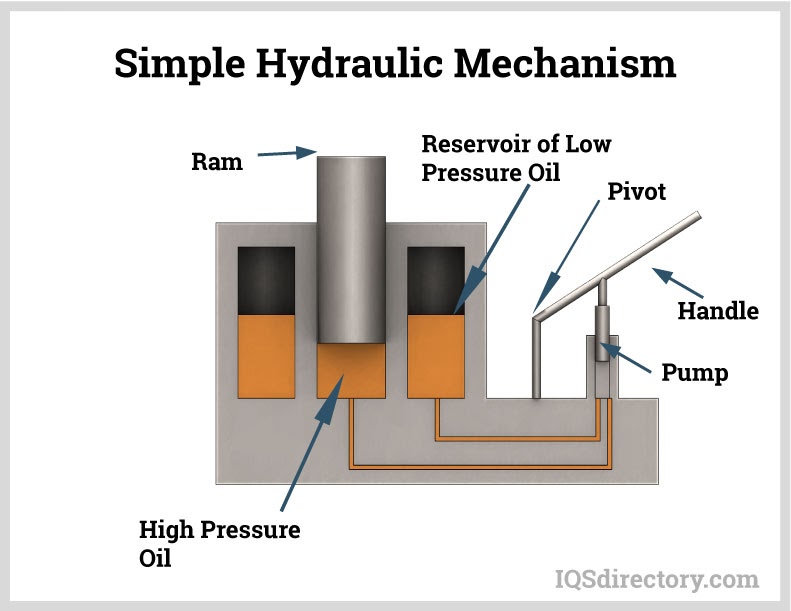
One hundred pounds of force by a small piston will be able to lift 900 pounds. In this diagram, the piston on the left has a one pound load and an area of one inch. When it moves down ten inches, it is able to move the ten pound load on the piston on the right. Parts of a Hydraulic System.

How Hydraulic Lifts Work Hydraulic Home Lifts Gartec Home
lift. The scissor lift will be incorporated onto a frame and be mounted below the dump bed. The scissor lift will have pivot points and a mounting bracket with the dump bed positioned on top of it. Description This scissor lift will reside on the trailer frame underneath the dump bed. There are two mounting points for the scissor lift.
1
Lift is the key aerodynamic force that keeps objects in the air. It is the force that opposes weight; thus, lift helps to keep an aircraft in the air. Weight is the force that works vertically by pulling all objects, including aircraft, toward the center of the Earth. In order to fly an aircraft, something (lift) needs to press it in the opposite

Introduction To Artificial Lift
The [second figure] provides supplementary information to illustrate the significance of the V-n diagram [shown earlier]. The lines of maximum lift capability are the first points of importance on the V-n diagram. The subject aircraft is capable of developing no more than one positive "g" at 100 knots, the wing level stall speed of the airplane.
Conphy Lurie A Diagram Of Car On Hydraulic Lift With Explanation
experience the sensation of lift. The instructor will present information about airfoil design, lift, and the Bernoulli Principle for all participants, but those in the 5th - 12th grades may engage in a brief discussion about the Area Rule and the difference between laminar flow airfoils and conventional airfoils. Objectives . Students will: 1.
Lift Right Ergo Ergonomic Scissor Lift Wiring Schematic Material Handling Equipment From Lift Rite North Central
Hydraulic Lift What Is It How It Works Types Application

How To Use A Hoyer Lift Proper Use Of Hoyer Lift Safety
Is There A Graph Of The Lift Generated By The Wings And Tail Of An Aircraft At Different Angles Of Attack Quora
Momentum Theory Of Lift How Things Fly

Lift Distribution An Overview Sciencedirect Topics
Bendpak P 6fb Pit Lift Service Manual Parts Diagram Manualzz
Suzuki Lift Circuit Schematic Diagram Motor Control Control Circuit Circuit Diagram Seekic Com
Bjorn S Corner Aircraft Lift Part 2 Leeham News And Analysis
Wl Model Lifts Western Lift Western Hoist
Traction Versus Hydraulic Lifts Advantages And Disadvantages
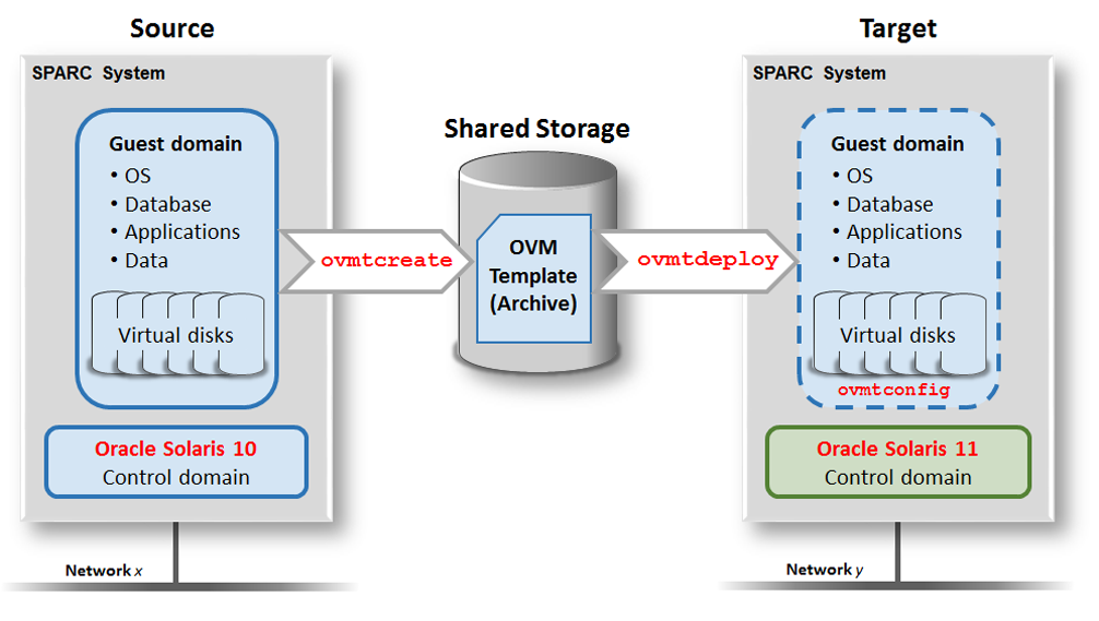
Lift And Shift Scenario Overview Lift And Shift Guide Moving Oracle Solaris 10 Guest Domains To Sparc Servers Running Oracle Solaris 11

Simplified Representation Of A Typical Conventional Traction Lift Download Scientific Diagram
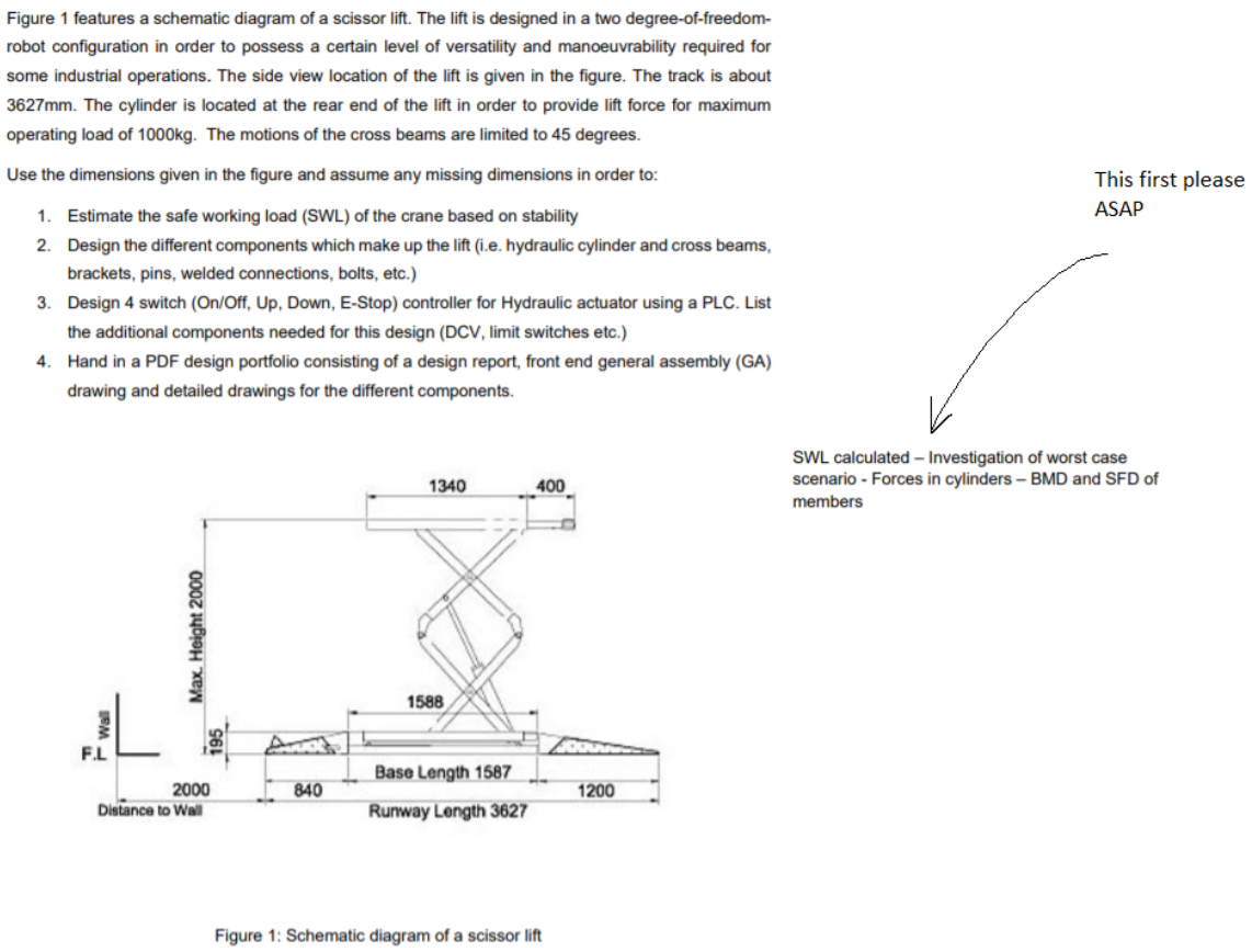
Figure 1 Features A Schematic Diagram Of A Scissor Chegg Com

Gravely 992301 000101 Pm250z 20hp Kohler 50 Deck Hyd Lift Parts Diagram For Wiring Diagram
Inclination Effects On Lift

Pin On Ascensore
Draw Layout Of Lift Irrigation Scheme And Explain In Brief Component Parts Of The Sam Discuss
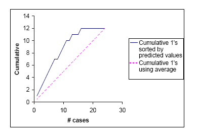
Lift Charts

Chain Lift Chain Lift Roller Coaster Diagram Transparent Png 663x467 Free Download On Nicepng

Aerodynamic Lift And Drag And The Theory Of Flight

Mobilift Cx Portable Wheelchair Lift Handiramp

General Force Diagram For A Lift Under Safety Gear Application Download Scientific Diagram
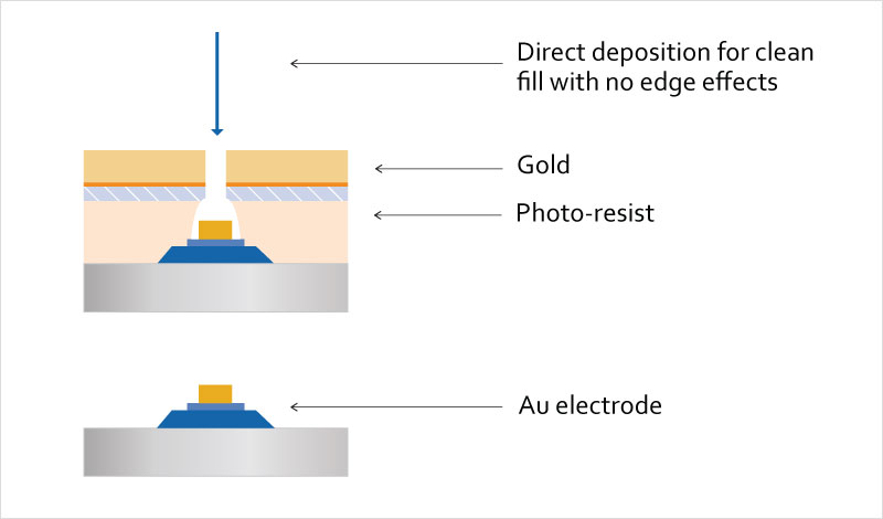
Considerations For Using Magnetron Sputtering For Lift Off Applications Denton Vacuum
Aerodynamic Lift And Drag And The Theory Of Flight

Hydraulic Lift Circuit Hydraulic Valve

Schematic Diagram Of An Elevator System Download Scientific Diagram

Wiring Diagram Genie Aerial Work Platform Elevator Scissor Lift Angle Electrical Wires Cable Png Pngegg
Lift Right Ergo Ergonomic Scissor Lift Wiring Schematic Material Handling Equipment From Lift Rite North Central


Comments
Post a Comment