43 radio block diagram
Radio schematic and block diagrams can be daunting to many. One way to understand is to break it up into stages or modules. Many stages do similar things, ... Block diagram of radio . AM Transmitter . In order to better understand the way the radio transmitter works, block - diagram of a simple AM (amplitude modulated) signal transmitter is shown on Pic. The amplitude modulation is being performed in a stage called the modulator. Two signals are entering it: high frequency signal called the carrier ...
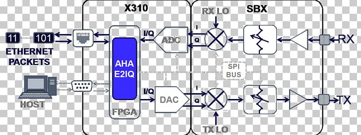
Block Diagram Software Radio Antenna RF IF Baseband DSP ADC/DAC. Smart Radios The positive control over the transmitter's use of the spectrum has traditionally been the purview of the radio operators, who were guided and trained to follow the rules of engagement carefully crafted
Radio block diagram
This super-heterodyne FM radio block diagram shows all the main stages of a modern radio. The first three stages are very similar to an AM radio block diagram; however, the main difference is in the limiter and FM detector stages, which are crucial to FM reception.These stages are responsible for decoding the frequency-modulated signal. Another re-posting of a previous video. This is an block diagram view of how an AM radio works section by section. Scicos: Block diagram modeler/simulator. Scicos is a graphical dynamical system modeler and simulator developed in the Metalau project at INRIA, Paris-Rocquencourt center. With Scicos, user can create block diagrams to model and simulate the dynamics of hybrid dynamical systems and compile models into executable code. Scicos is used for signal processing, systems control, queuing systems, and ...
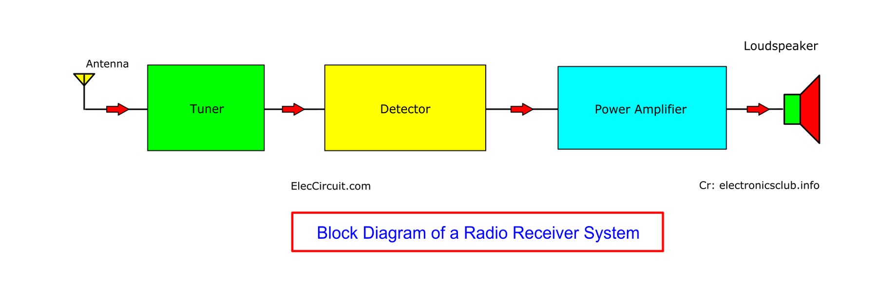
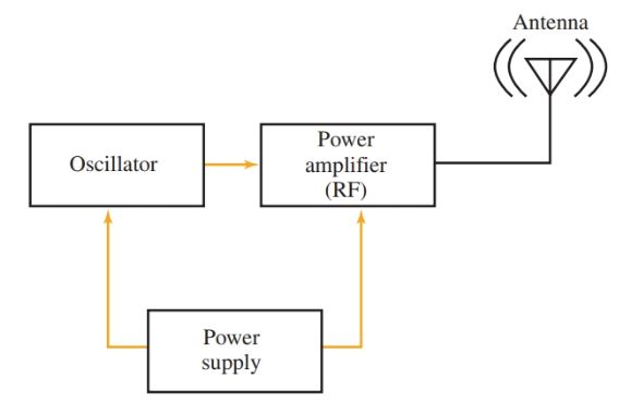
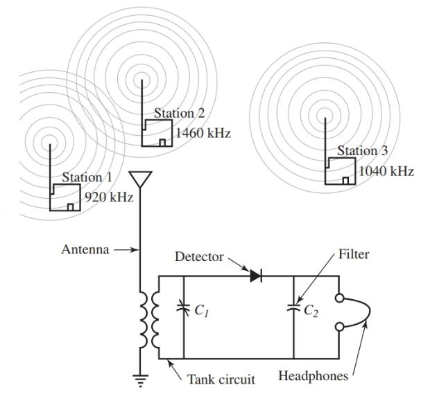
Radio block diagram. A block diagram of a simple continuous wave (CW) transmitter is shown in Figure 6. The first block is the conventional crystal oscillator and then the final power amplifier. A power supply is provided for the oscillator and the final power amplifier. Figure 6. A block diagram representing various stages of a basic continuous wave radio transmitter. SDR Receiver Block Diagram Figure 9 Principles of SDR Figure 10 Figure 9 shows a block diagram of a software SDR Receiver Mixer defined radio receiver. The RF tuner converts analog RF signals to analog IF frequencies, the same as the first three stages of the analog receiver. The A/D converter that follows digitizes the IF signal The block diagram of a Tuned Radio Frequency (TRF) receiver is shown in the figure. Infinite number of transmitters installed throughout the world radiates radio waves in space. In general, these transmitters radiate different frequencies. Electromagnetic waves surrounding an antenna will induce currents of their frequency in the antenna. FM Receiver Working Principle. To easily understand the working principle of FM Receiver, see the block diagram. The first block is the Antenna. The antenna is used to receive the radio signals and intercepted it. The next block is Radio Frequency Amplifier or RF amplifier. The RF amplifier is used to amplify the RF signal received by the antenna.
Example circuit diagram of radio receiver : This is example of radio receiver for specific frequency but it has stages mentioned in the block diagram above. Local oscillator is using crystal (x1) and received signal is mixed in FET mixer BF244B transistor. This article discusses what is quadrature amplitude modulation, its definition, block diagram, working principle, and it’s applications. What is Quadrature Amplitude Modulation? Quadrature amplitude modulation (QAM) is modulation techniques that we can utilize in analog modulation concept and digital modulation concept. Depending upon the input signal form we can use it in either analog or ... 3. Block diagram design (rough outline) 4. Details for each block (equipment selection, interconnections) 5. Determine plan of action (timetable, which pieces first) 6. Constant feedback — things come up, so modify the plan as needed K9AY — ZO FEST 2009 FM Transmitter Working Principle. The main function of an FM Transmitter Circuit is to transmit the sound using radio waves. So, at first, an FM Transmitter Circuit converts the sound or audio into radio wave then it transmit. You can see, in the block diagram of the FM Transmitter, the first block is the Microphone.
The RF front-end comprises a low-noise amplifier (LNA), quadrature mixers, and active RC low-pass filters with gain control. Quadrature local oscillator (LO) ... Block Diagrams. Block diagrams are used to understand (and design) complete circuits by breaking them down into smaller sections or blocks. Each block performs a particular function and the block diagram shows how they are connected together. No attempt is made to show the components used within a block, only the inputs and outputs are shown. Visualize the big picture of the AM radio transmitter, receiver, and interfering signals with a system block diagram. Each block in the diagram has an underlying mathematical model. Start with the AM signal model The signal model for an AM signal is where Ac is the carrier amplitude, fc is the carrier frequency, m(t) is […] It is also a good idea to explain each unit of the block diagram individually. ... Radio - It is a signaling and communication technology. Radio uses waves in the ...1 answer · Top answer: Hint - Start the solution by describing the general concept behind a radio. Then draw a well-labelled block diagram of the radio receiver. It is also ...
Fm Receiver Block Diagram Intermediate Frequency And If Amplifiers
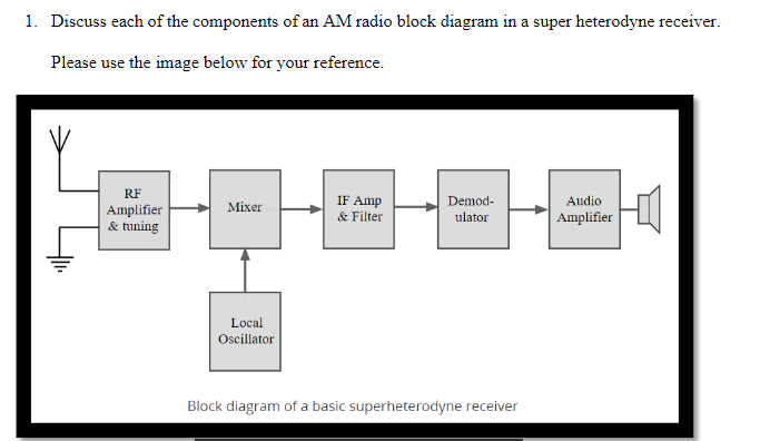
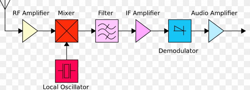
Block diagram of a basic superheterodyne radio receiver The way in which the receiver works can be seen by following the signal as is passes through the receiver. Front end amplifier and tuning block : Signals enter the front end circuitry from the antenna.
Superheterodyne Am Receiver Working With Block Diagram And Schematics
Figure A: Decode Block Diagram. From RF to audio. On the right side RF signals are coming in from your antenna setup and are being fed to your receiver. These can be traditional or software defined receiver. ... radio.1.name=Radio radio.1.address=localhost radio.1.port=9100 radio.1.type=KISS radio.1.tncport=1.

Eetimes Digital Receiver Design Basics Of Software Radio Part 1
A block diagram is a diagram of a system in which the principal parts or functions are represented by blocks connected by lines that show the relationships of the blocks. They are heavily used in engineering in hardware design, electronic design, software design, and process flow diagrams.. Block diagrams are typically used for higher level, less detailed descriptions that are intended to ...

Thinkrf R5500 Software Defined Radio Block Diagram Thinkrf
radio circuits. Objectives: - Label the components of a generic radio block diagram. - Explain the path that an RF signal follows within a system during reception and transmission. - Explain the function of an oscillator. - Identify the factors that influence oscillator performance.
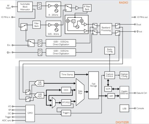
Thinkrf R5500 Software Defined Radio Block Diagram Thinkrf
Digital radio works by converting sound into digital code, transmitting the code as a digital signal, and digital radio receivers are able to decode and filter all but the digital signals for static-free sound on the receiving end. Digital radios are also easier to use since they allow menu-based operation and support the Radio Data System (RDS ...
3 Transistor Short Wave Radio
Demodulator: The superheterodyne receiver block diagram only shows one demodulator, but in reality many radio RF designs may have one or more demodulators dependent upon the type of signals being receiver. Those radios used for professional radio communications applications and monitoring may need to be able to demodulate a variety of modulation schemes and waveforms and this may require a ...
Understanding Electronics Block Diagrams With Example Eleccircuit Com
A.M. Receiver Tutorial & Circuits - A.M. Receivers - Block Diagram - Electronics Circuit and Tutorials - Hobby Science Projects - Most of these blocks are discussed individually, and in more detail, on other pages. See filters, mixers, frequency changers, am modulation and amplifiers. Learn everything about AM Receiver

Nxp S Radio Unit Block Diagram Electronic Products
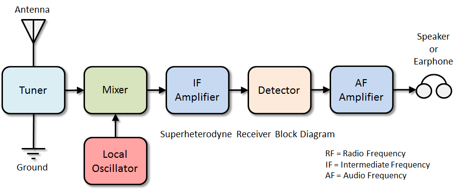
A block diagram of radio is given below. First RF signal is received with the help of Arial/antenna. Then this signal is amplified in RF amplifier stage. A local oscillator is used to generate high frequency signal. Then in mixer stage both RF signal and local oscillator signal is mixed to produce intermediate frequency signal (IF).

Block Diagram Of Transceiver For Ham Radio Applications Download Scientific Diagram
This is a block diagram of a simple Amateur Radio station. Let's discuss the blocks one at a time. Section 4.1 TRANSMITTERS The heart of a radio station is the transmitter. It is a device that will transmit radio signals out over the air. These signals are often called RF, for radio-frequency signals. A TV station or
Universal Software Radio Peripheral Software Defined Radio Block Diagram Modulation Computer Software Png Clipart Angle Area
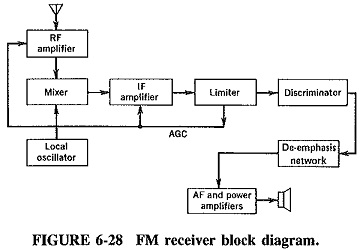
Block Diagram of FM Receiver with Explanation. Standard broadcast for FM is 88-108 MHz. The maximum permissible deviation is 200 KHz. In FM the intermediate frequency is 10.7 MHz. In FM the operating frequencies are much higher than that in AM. It additionally contain a de-emphasis and limiter circuit. The method of demodulation is totally ...

Radio Installation Electropedia
Understanding Electronics Block Diagrams With Example Eleccircuit Com. Small Fm Radio Circuit. Radio Transmitter And Receiver Working Block Diagram Electrical Academia. Block Diagram Radio Frequency Circuit Rf Module Png 769x513px Area. Simplified Block Diagram Of An Am Fm Radio With Digital Audio Signal Scientific. Superheterodyne Fm Receiver.
Gsm0108 Gprs Radio Modem Block Diagram Novatel Wireless
Radio receiver design includes the electronic design of different components of a radio receiver which processes the radio frequency signal from an antenna in order to produce usable information such as audio. The complexity of a modern receiver and the possible range of circuitry and methods employed are more generally covered in electronics and communications engineering.

Ti S Digital Radio Block Diagram Electronic Products
FM Radio Block Diagram 14: FM Radio Receiver •FM Radio Block Diagram •Aliased ADC •Channel Selection •Channel Selection (1) •Channel Selection (2) •Channel Selection (3) •FM Demodulator •Differentiation Filter •Pilot tone extraction + •Polyphase Pilot tone •Summary DSP and Digital Filters (2017-10178) FM Radio: 14 - 2 / 12 FM spectrum: 87.5 to 108MHz
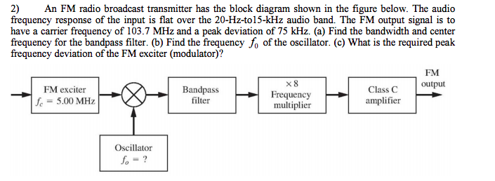
Solved 2 An Fm Radio Broadcast Transmitter Has The Block Chegg Com
02.05.2020 · The Block diagram of 3 to 8 Decoder: 3 to 8 Decoder designing steps. Problem: 3 to 8 line decoder. The number of available inputs are 3 and outputs are 8. Let us represent the inputs and outputs by symbol letters. Let us represent the inputs by x, y, and z; and the outputs by D 0, D 1, D 2, … D 7. 3 to 8 Decoder Truth Table: Now functions. Simplified Boolean function. The above function ...

Schematic Block Diagram Of A Digital Radio Download Scientific Diagram
13.08.2017 · The block diagram of a function generator is given in the figure. In this instrument, the frequency is controlled by varying the magnitude of the current that drives the integrator. This instrument provides different types of waveforms (such as sinusoidal, triangular and square waves) as its output signal with a frequency range of 0.01 Hz to 100 kHz. The frequency controlled voltage regulates ...
Radio Transmitter And Receiver Working Block Diagram Electrical Academia
Fig. 2 shows the block diagram of a SDR receiver. At first, the RF tuner converts the analog signal to IF, performing the same operation that the first three blocks of the superheterodyne receiver. Up to this point the two schemes converge [21]. FIg. 2. Block Diagram of the SDR Receiver. Next, the IF signal is passed to the ADC converter

Microwave Radio Front End Block Diagram Electronic Products
Block diagrams are an ideal resource for communicating a high-level overview of your system to stakeholders and less technical employees. With our block diagram software, you can take advantage of powerful collaboration features like in-editor chat, comments, and @mention notifications to enable teams to work together in real time, no matter their device or location.
Two Way Radio Edit Analog Cellular Transceiver Block Diagram 500x249 Png Download Pngkit
Telephone, radio, television, internet, and military applications use satellite communications. Believe it or not, more than 2000 artificial satellites are hurtling around in space right above your heads. Satellite Communication Block Diagram. Need for Satellite Communication. We know that there are different ways to communicate and the propagation of these waves can take place in different ...

Block Diagram Of The Vhf Receiver For Receiving Fm Radio Signal Figure Download Scientific Diagram
Digital radio is taking the old broadcast medium into the digital age with crystal-clear music, hundreds of new stations, on-demand radio, surround sound, rewind radio and more. Menu. ... TI's Digital Radio Block Diagram. Posted on November 18, 2013 by Electronic Products ...

Software Defined Radio Pantech Prolabs India Pvt Ltd
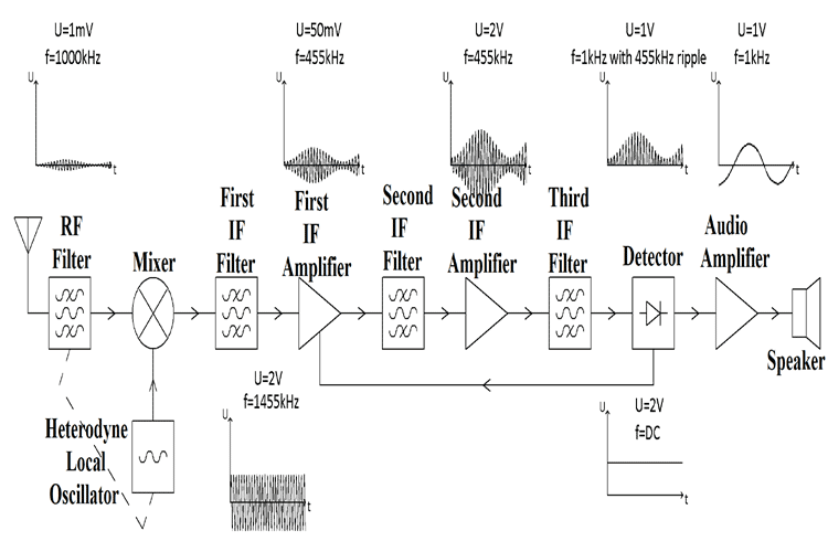
12.03.2020 · A superheterodyne receiver uses signal mixing to convert the input radio signal into a steady intermediate frequency (IF) ... To understand how it works, let’s take a look at the Superheterodyne AM Receiver Block Diagram which is shown below. As you can see the block diagram has 11 different stages, each stage has a specific function which is explained below. RF …
30835hs45 Digital 5 Channel Fm Radio Control System Block Diagram Sgz Block Hobby Shack
Superheterodyne Radio Receiver Block Diagram. Here is a block diagram of a typical superheterodyne (superhet) radio receiver, together with theory and notes explaining each block. I have kept the theory very simple and at introductory level for beginners, however at some point there will be another article taking it further.
Brats Advanced Amateur Radio Tuition Course
Pasternack's library RF and microwave block diagram are designed to provide engineers and designers with examples of common RF systems schematics while illustrating the RF products and where they fit into the system's design.
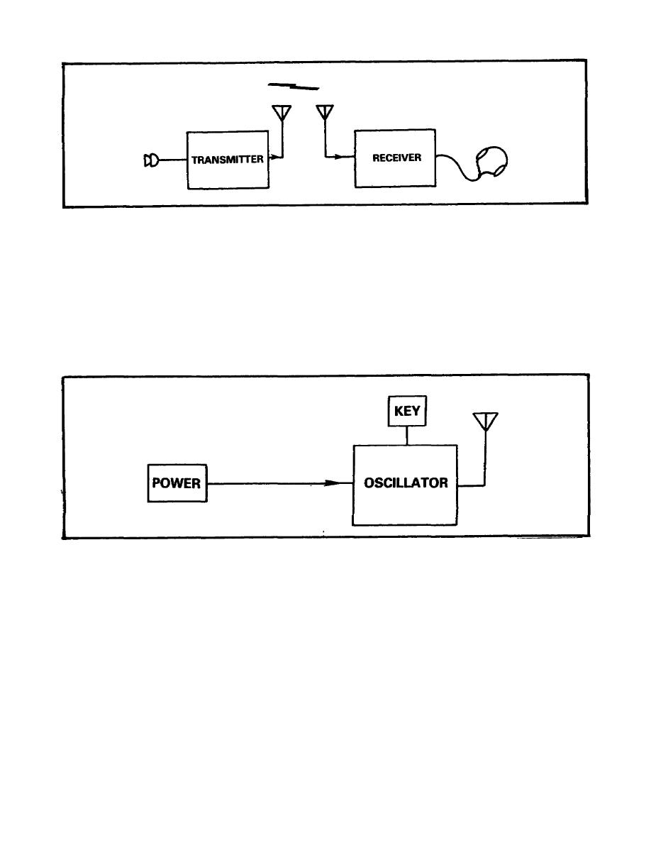
Figure 1 Block Diagram Of Basic Radio Set
Scicos: Block diagram modeler/simulator. Scicos is a graphical dynamical system modeler and simulator developed in the Metalau project at INRIA, Paris-Rocquencourt center. With Scicos, user can create block diagrams to model and simulate the dynamics of hybrid dynamical systems and compile models into executable code. Scicos is used for signal processing, systems control, queuing systems, and ...
2
Another re-posting of a previous video. This is an block diagram view of how an AM radio works section by section.
Flashwebhost Com Block Diagram Of 7mhz Ssb Ham Radio Transceiver Using Mc1496 Irf840 And Ladder Filter
This super-heterodyne FM radio block diagram shows all the main stages of a modern radio. The first three stages are very similar to an AM radio block diagram; however, the main difference is in the limiter and FM detector stages, which are crucial to FM reception.These stages are responsible for decoding the frequency-modulated signal.

Optimising Digital Rf Communication Systems
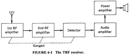
Tuned Radio Frequency Receiver
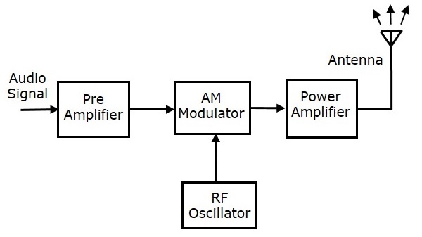
Analog Communication Transmitters
1
Radio Transmitter And Receiver Working Block Diagram Electrical Academia

Radio Communication Radio Transmitters And Receivers
F M Receiver Tutorial Block Diagrams Electronics Circuit And Tutorials Hobby Science Projects

Bits To Beams Rf Technology Evolution For 5g Millimeter Wave Radios Analog Devices

Tuned Radio Frequency Trf Receiver Block Diagram Electronics And Communication Study Materials

Vhf Fm Marine Radiotelephone Jhs 32b Schematic Diagram Jrc Japan Radio Co Ltd

Ee16a Wireless Lab1

Download Two Way Radio Edit Analog Cellular Transceiver Block Diagram Full Size Png Image Pngkit

Fm Radio Receiver Youtube
Reflex Radio Receivers

A M Receiver Tutorial Circuits A M Receivers Block Diagrams Electronics Circuit And Tutorials Hobby Science Projects
Solved 1 Discuss Each Of The Components Of An Am Radio Chegg Com
Superheterodyne Receiver Radio Receiver Block Diagram Png 1600x576px Superheterodyne Receiver Area Block Diagram Brand Circuit Diagram

Functional Block Diagram Of A Radio Receiver A Conventional Radio Download Scientific Diagram


Comments
Post a Comment