38 alternator voltage regulator circuit diagram
Alternator voltage must be above 10.0-volts and the communication must begin within 3-seconds or the ECM will set a trouble code. The ECM set a charging voltage of 12.5-14.5-volts. The internal voltage regulator monitors the alternator output and reports it to the ECM. In this video we will be dealing with wiring up fuse 9. The electrical system on 6 and 12 volt vws up to and including 1972 used a generator to produce power a voltage regulator to set the charging level and a battery to store the power. Vw 1500 sedan and convertible wiring key. 1967 vw beetle alternator. Pin On 4 H.
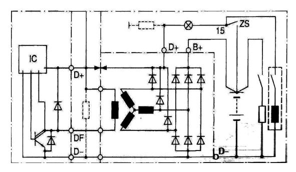
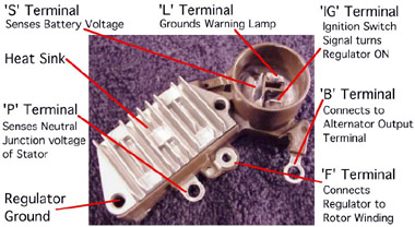
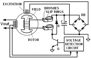
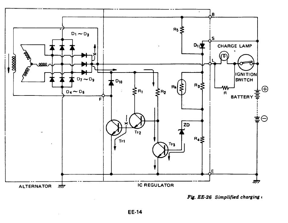
A typical electronic voltage regulator is shown in FIG. 23. This circuit senses the battery voltage and causes the alternator to deliver either full charge ...

Alternator voltage regulator circuit diagram
Alternator Voltage Regulator Wiring Diagram wiring diagram is a simplified tolerable pictorial representation of an electrical circuit. Wiring instructions for the early GM Delco Remy external regulated alternator. The alternator rotor spins inside the windings of the stator. This simple hybrid solar charger can charge a battery using both ... Alternator Wiring Diagrams 3 Wire Alternator Wiring Diagram. It shows the components of the. Wiring A Bosch Voltage Regulator If You Have A Bosch Regulator These Are The Designations Voltage Regulator Electric Trike Electricity A typical 3-wire alternator wiring diagram with an internal voltage regulator. Computer-Controlled Voltage Regulation. Many late-model vehicles use the engine computer, which is often referred to as the powertrain control module (PCM), to control alternator output. Most modules use an internal driver to turn the alternator's field circuit on ...
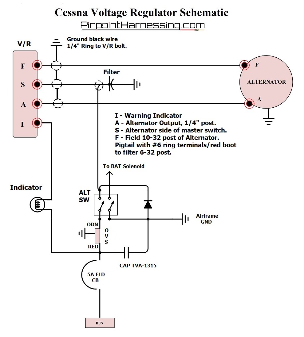
Alternator voltage regulator circuit diagram. The F wire runs from the regulator to the alt. It regulates how much power goes to the alternator field wiring as I recall. The higher the voltage the reg sends to the alt field the higher higher alternator amp and voltage output. You have the fusible link (Usually goes from the + terminal on the alt to the starter solenoid and back feeds from ... Ford alternator wiring diagrams 65 impala diagram internal motorcraft regulator help needed voltage crown victoria 1989 gm full 1990 trouble shooting A voltage regulator will limit the maximum amount of voltage from a power source and prevents a device or alternator from shorting and overheating. Jan 11, 2016 - Self build adjustable alternator controler. ... AC Generator Circuit Diagram with Internal Regulator. | Electrical Engineering Blog. Alternator Voltage Regulator Wiring Diagram wiring diagram is a simplified tolerable pictorial representation of an electrical circuit. 12 volt alternator voltage regulator diagram. Alternator Voltage Regulator Circuit Schematic Posted by Margaret Byrd Posted on May 17 2018 Automotive alternator schematic diagram of voltage regulator 4 solid ...
Motorola Alternator Wiring Diagram - 24 volt motorola alternator wiring diagram, motorola alternator wiring diagram, motorola alternator wiring diagram john deere, Every electric structure is composed of various different components. Each part ought to be set and connected with different parts in specific manner. If not, the structure won't function as it should be. Delco remy alternator wiring diagram 4 wire wiring diagram is a simplified agreeable pictorial representation of an electrical circuit it shows the components of the circuit as simplified shapes and the knack and signal links with the devices. Retrofitting old stlye delco remy regulator to new style delco remy 50vr regulator. 4 Wire Alternator Voltage Regulator Diagram | Wiring Diagram - Voltage Regulator Wiring Diagram. Additionally, Wiring Diagram provides you with time frame by which the projects are to become finished. You will be in a position to know specifically when the projects should be accomplished, that makes it much easier for you personally to ... The regulator is forced to a minimum short circuit duty cycle. Figure 3. IAR System Block Diagram. BATT. IGNITION. SWITCH. Regulator. A.10 pages
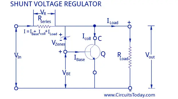
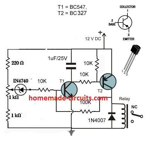
How to Set up the Circuit. For a 12V system, apply a 18V from a DC power supply from the T1 side, and adjust R4 to precisely set 14.4V across the output terminals. An even simpler motorcycle shunt regulator using the shunt regulator IC TL431 can be witnessed below, the 3k3 resistor can eb tweaked to chnage the output voltage to the most ... 14+ Alternator Ic Regulator Diagram. A wide variety of alternator voltage regulator circuit diagram options are available to you, such as phase. In this circuit, vin is the input voltage to the 7805 ic and the source can be from either a battery of an unregulated dc. POWER CARS: and… Back view of a standard ford alternator. Voltage regulator ford 15 volt negative ground alternator. 21 Ford Harness Wiring Diagram Bookingritzcarlton Info In 2020 Diagram Alternator Ford 1967 f 100 thru f 350 ignition charging starting and gauges. 1970 ford f100 alternator wiring diagram. Posted by 177 30 diagram thierryluangrath fr on. Alternator wiring with … Step 3 remove the 2 wires from the generator these 2 leads go to the old voltage regulator. Step 2 install the regulator to the shock tower. Wiring instructions for the early gm delco remy external regulated alternator. Step 2 locate the voltage regulator usually on the firewall. These wires connect to the generator and you don t need them.
Alternator Function And Alternator Wiring Diagram In Car Etechnog
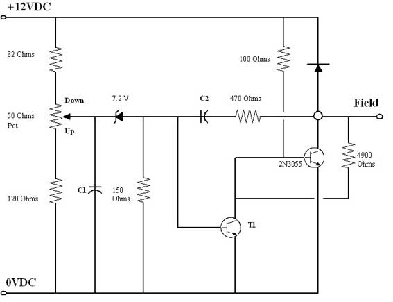
Voltage regulator for DC alternators;. This is about an alternator regulator you can build yourself for a few dollars, suitable for ... wiring diagram volt reg.
Regulators
Wiring Diagram VW GOLF 2009 - Battery - starter - alternator - voltage regulator ABattery BStarter CAlternator C1Voltage regulator J623Engine control unit S176Fuse 4 (30) in fuse holder on battery S177Fuse 5 (30) in fuse holder on battery T1aSingle pin connector, on the battery T2o2-pin connector, on alternator T4w4-pin connector, VW GOLF 2009 - Radio .

Voltage Regulator Ext How It Works Ih8mud Forum
Mitsubishi alternator retrofit 1g voltage sensing wire 92 hyundai excel question ls conversion swap information wiring hi i need help in 09 11 cts v ls1tech common 2 pin connector victoria diagrams regulator installation serpentine Wiring Question Ford Big Case Mitsubishi Alternator Retrofit Ih8mud Forum 1g Alternator Voltage Sensing Wire Dsmtuners Com 92 Hyundai Excel Alternator… Read More »

Self Build Adjustable Alternator Controler Alternator Voltage Regulator Car Alternator
Alternator wiring diagram with voltage regulator. Ford alternator regulator wiring diagram effectively read a cabling diagram, one provides to learn how the components inside the method operate. If the voltage is 13.5v or more with the engine running, there is a connection problem downstream. To battery generator 2f428 delco remy 12 volt ...
Car Alternator Rectifier Question
Hitachi Yanmar Alternator Machine Sensed Or Battery Cruisers Sailing Forums. Self regulating alternator with internal regulator excited single phase build adjule controler alternators gm external regulated 10dn voltage regulation 101 troubleshooting one wire convert to wiring and testing ford lima mac ser generator owner manual 12v dc part 2 tech bosch circuit from scratch universal diagrams ...

Automotive Charging Systems A Short Course On How They Work Carparts Com
Common problem with these old Ford diesels. 12.4 V is not enough voltage from your alternator, but it might be pulled down by a discharged battery?? Should be 13.5 - 14V. I would charge the battery up and then check the voltage. If the voltage remains at 12.4, your alternator is not putting out.
Automotive Alternators Internal Circuit And Output Voltage Regulation Automobile Electrical System Components Control Units Systems Integration
LM338 Schematic Diagram. Regulator circuit diagram. In the switching regulator section the Buck Buck-boost Boost and Flyback topologies will be detailed. The variable resistor in the circuit above is used to represent the actions of a current regulator. Design of 9 v regulator using 7809 with lm7811 voltage 5a variable power supply lm338 lm317 ...
Voltage Regulators Circuits Types Working Principle Design Applications
Ford 302 voltage regulator wiring diagram. Ford 3600 Wiring Diagram Collection. Thats why there are numerous guidelines surrounding electrical cabling and installations. Wiring Diagram With Alternator Club Cobra. My wiring diagram only shows 3 wires coming out of the voltage regulator and a 4th that is the radio suppression condensor.

Alternator Voltage Regulation 101 With Wiring Diagrams In The Garage With Carparts Com
Wiring Diagram Alternator Voltage Regulator Fresh 4 Wire Auto - Alternator Wiring Diagram Wiring Diagram includes numerous in depth illustrations that display the link of various things. It includes guidelines and diagrams for different types of wiring techniques and other things like lights, home windows, etc.

High Power Car Voltage Regulator
Ford Alternator Wiring Diagram Internal Regulator - ford alternator wiring diagram internal regulator, Every electrical arrangement is made up of various diverse parts. Each part ought to be set and connected with different parts in specific manner. If not, the structure will not work as it ought to be.
Ford Alternator And An Ext Voltage Regulator Install Ford Truck Enthusiasts Forums
Vw generator alternator wiring guide fanáticos de los volkswagens volky beetle voltage regulator diagram facebook thesamba com 1958 1967 view topic late model super 1968 up old car new engine mis match charging system tests madcomics. Category: Wiring. Margaret Byrd ...

Dc Voltage Regulator Circuit
Posted: Fri May 28, 2021 6:02 am Post subject: Re: IH 140 electrical system: Google Bob M's wiring diagrams. The 6V generator/regulator wiring is the same as your 12V. Also the diagrams for 12V alternator conversions are the same, except you don't have to swap the wires on the ammeter, it's already negative ground.
The Alternator Regulator Voltage Booster Modification Part 1 Introduction Ih8mud Forum
Jul 2, 2020 — Referring lo the nest solid-state alternator voltage current regulator diagram below, V4 is configured like a series-pass transistor which ...
Voltage Regulator For Permanent Magnet Alternators
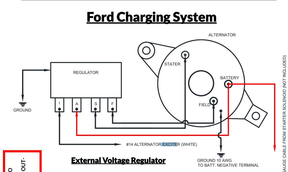
It shows how ford external voltage regulator connects to the ignition switch, starter solenoid, ford externally regulated alternator, as well as the battery. 17 78 ford truck 302 vacuum diagram ford truck ford f250 ford from www.pinterest.com. Electric fuel pump control, trailer, trailer,fuse link, starter relay, battery, field switch, fuse ...
What Is A Voltage Regulator News About Energy Storage Batteries Climate Change And The Environment
(field monitor) short circuit protected. □ Load response control ... Voltage regulator intended for use in automotive ... Block diagram .11 pages
Alternator Regulator Troubleshooting
Alternator regulator wiring diagram. A wiring diagram is a streamlined conventional photographic depiction of an electric circuit. Wiring diagram arrives with several easy to stick to wiring diagram directions. Connecting the sense wire to the batteries causes the alternator to output extra voltage to compensate for the voltage drop in the ...
Electric Circuit Diagram Alternator Voltage Regulator 314 7755 Buy Electric Circuit 314 7755 Alternator Voltage Regulator Electric Circuit Diagram Product On Alibaba Com
A typical 3-wire alternator wiring diagram with an internal voltage regulator. Computer-Controlled Voltage Regulation. Many late-model vehicles use the engine computer, which is often referred to as the powertrain control module (PCM), to control alternator output. Most modules use an internal driver to turn the alternator's field circuit on ...

Alternators Voltage Sensing Marine How To
Alternator Wiring Diagrams 3 Wire Alternator Wiring Diagram. It shows the components of the. Wiring A Bosch Voltage Regulator If You Have A Bosch Regulator These Are The Designations Voltage Regulator Electric Trike Electricity
Ford Alternator W External Regulator The H A M B
Alternator Voltage Regulator Wiring Diagram wiring diagram is a simplified tolerable pictorial representation of an electrical circuit. Wiring instructions for the early GM Delco Remy external regulated alternator. The alternator rotor spins inside the windings of the stator. This simple hybrid solar charger can charge a battery using both ...
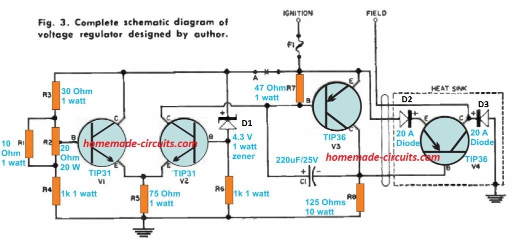
4 Solid State Car Alternator Regulator Circuits Explored Homemade Circuit Projects

Reyhan Blog Bosch Alternator Voltage Regulator Circuit
Designing An Automotive Alternator S Voltage Regulator How To Avoid Magnetic Saturation In The Rotor Electrical Engineering Stack Exchange
Automatic Voltage Regulator Avr For Generators
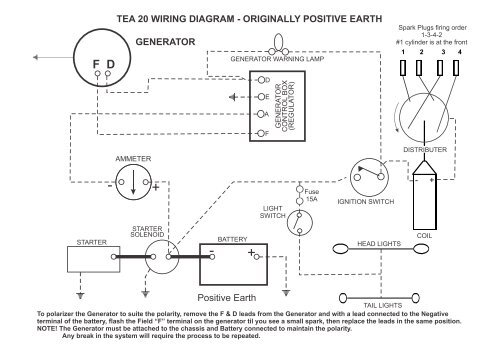
Te20 Generator And Alternator Wiring Diagrams
1
Ki Davr 95s Alternator Engine Set Automatic Voltage Regulator Circuit Diagram 3 Phase Generator Spare Parts Avr 95s3 95sw Generator Parts Accessories Aliexpress
Thesamba Com Bay Window Bus View Topic In Search For Charging Solution

Single Wire Alternator Chevy Voltage Regulator Circuit Ac Delco Lovely Remy Wiring Diagram With Voltage Regulator Alternator Electrical Wiring Diagram

Alternator Voltage Regulator Excitation System Theteche Com
1
Voltage Regulator Working Principle Circuit Diagram Voltage Regulator In Power Supply Electrical Academia
What Is A Voltage Regulator News About Energy Storage Batteries Climate Change And The Environment

Advanced Auto Electrical Systems Troubleshooting
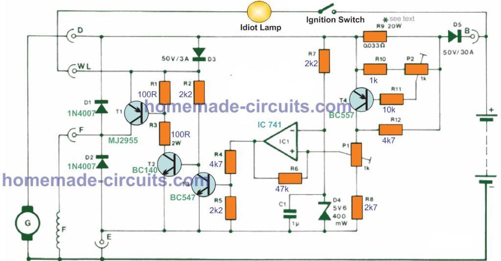
4 Solid State Car Alternator Regulator Circuits Explored Homemade Circuit Projects
Content Electrical Voltage Regulator S3 E Type

Adjustable Regulator On An Internally Regulated Alternator S V Hajime Begin
Schematic Diagram Electronic Voltage Regulator Bmw Airhead Motorcycle
4 Solid State Car Alternator Regulator Circuits Explored Homemade Circuit Projects


Comments
Post a Comment