38 ammeter wiring diagram
I have a 12vdc lithium battery pack so i have used a [LM317 module](http://www.ebay.com/itm/271712302481) to get 5vdc and connected it to the RTL dongle according to the [pinout diagram](https://upload.wikimedia.org/wikipedia/commons/thumb/6/67/USB.svg/220px-USB.svg.png) with the data wires coming from the pc USB and the power supply from the LM317 module. Result: the dongle is not recognized I have power on the dongle, i can see it with a [passthrough usb voltmeter](http://www.aliexpress.com/it... Aim: to find out how the amount of current affect the amount of copper deposited at the cathode during the electrolysis of copper sulphate with inert graphite electrodes Hypothesis: Michael Faraday’s first law of electrolysis states: “The mass of any element deposited during electrolysis is directly proportional to the number of coulombs of electricity passed” From this statement we can say that the amount of electricity that we pass in the circuit will directly affect the rate of electrol...
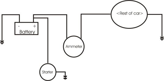
[Wiring Diagram](https://i.imgur.com/Ga8zm9p.jpg) Hi, I’m hoping someone will be able to give a little insight to what might have gone wrong here. Today we were trying to rewire my Ford 2N back to a 6V system, because I recently got the original generator rebuilt. We followed the diagram that I linked above, and right when we connected the battery the wire going from the ammeter to the starter switch burned up. We quickly unhooked the battery and double checked all the wires to make sure we ha...
Ammeter wiring diagram
Ok so this is a writing task and the full question is: *Describe how you would use a voltmeter, ammeter and other standard laboratory equipment to obtain accurate and reliable measurement of the resistance of a wire at temperatures between 0C and 100C. Your desciption should include: - A labelled circuit diagram <-- main problem - Details of measurements you would take <-- small problem - An account of how you would use your measurements <-- not really a problem - Details of how to imp... I built the first circuit on this page (http://www.homemade-circuits.com/2012/05/make-this-simple-tachometer-circuit.html?m=1), but with a few modifications. I changed the BC547 for an S8050 NPN transistor, and didn't have a capacitor of the right size so I put a couple in parallel to add to the correct value. On the diagram, for the final output, it shows a 10V FSD meter wired like an ammeter would be. I've tried searching online, but I can't seem to find out what an FSD meter is. Does anyone... Three Phase Ct Meter Wiring Diagram Posted by Margaret Byrd Posted on August 31 2018. These are generally older 3-phase systems. Single Phase Ammeter Voltmeter Connection Earth Bondhon How To Be Outgoing Connection Single You will need 1 Omnimeter and only 2 CTs for this kind of a system. 3 phase ct meter wiring diagram. […]
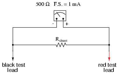
Ammeter wiring diagram. Hello and thank you for reading. I have purchased an ammeter online and I am unsure how to wire the display. I can't find any information on the product and it was shipped without literature. It's a coil ammeter. There are 2 leads to the coil. There are another 2 contacts on the back of the ammeter I assume are to power the display. I am unsure what to wire the display contacts too. Here's a link for the product. https://safetyelectrical.en.made-in-china.com/product/lNxJHUsdAVkM/China-Ad101-2... Digital ammeter circuit and project icl7107 icl7106 led volt ampere meter multimeter using how to make a voltmeter lcd panel wiring diagram pic working principle module Digital Ammeter Circuit And Project Using Pic Microcontroller Icl7107 Icl7106 Digital Led Ammeter Ampere Meter Digital Volt Ampere Meter Digital Multimeter Circuit Using Icl7107 How To Make A… Read More » Amp Meter Wiring Diagram. Amp Meter Wiring Diagram from www.chanish.org. Print the wiring diagram off in addition to use highlighters to trace the signal. When you employ your finger or the actual circuit with your eyes, it may be easy to mistrace the circuit. A single trick that We 2 to print exactly the same wiring picture off twice. I bought a [small 50A voltmeter/ammeter from Amazon](https://www.amazon.com/gp/product/B017FSED9I/ref=s9_simh_gw_g60_i1_r?ie=UTF8&fpl=fresh&pf_rd_m=ATVPDKIKX0DER&pf_rd_s=&pf_rd_r=GJ2CSJ6X98Y76X5A06YN&pf_rd_t=36701&pf_rd_p=14bf09e4-93c8-43ff-8639-e7979e7d1787&pf_rd_i=desktop&tag=vs-outdoors-convert-amazon-20), and I've been having a terrible time getting it wired in. The wiring diagram shows the shunt being wired into the negative side of the converter. Since th...
Ammeter wiring diagram wiring diagram is a simplified good enough pictorial representation of an electrical circuit. It reveals the elements of the circuit as simplified forms and the power and signal connections between the devices. Connect one end to terminal post on fuel level sender and the opposite end to the sender s terminal spade on ... Converting your classic car to self regulating alternator austin motor scene wiring for with internal regulator corvetteforum chevrolet corvette forum discussion connection diagram of the regulated excited single phase scientific build adjule controler alternators how wire a gm external 10dn voltage regulation 101 diagrams in garage carparts com troubleshooting one convert l1500 175 ... Dc Ammeter Shunt Wiring Diagram L Fd8e3c77ca6fd112 Gif 1479 786 Diagram Car Amplifier Gauges . In the event there is no link to pma or tso it has not been posted to the faa web site yet. Voltage regulator voltmeter wiring diagram. Gearshift methodsorders Manual operat ionL-H-N-R-P. Voltage Regulator Wiring Diagram wiring diagram is a simplified ... I have been doing my research, but my results have come up as "maybe". The engine is a 66 Johnson 40 HP outboard. The wiring diagram is [here](http://www.maxrules.com/graphics/omc/wiring/61_66_40HP.jpg) So, I have for the 5 terminal switch as each terminal goes to one place. Those are choke switch, starter solenoid, cut out switch, right side of ammeter, and upper cylinder. If I'm wrong, please correct me. So, looking at the 3 terminals on the one I picked up, I have them labelled as Sol, Bat...
I had these two components wired up as [shown here](https://imgur.com/a/sIcxi8j) but with extra components alongside and the magic smoke escaped from both components and just about set the meter on fire! I don't understand why, everything worked with the positive output to the battery disconnected and the meter displayed the solar panel voltage but when I reconnected the battery positive via a Schottky diode the smoke escaped! Overall connection diagram: [https://imgur.com/a/7dFJzmg](https:... Tractor ammeter wiring diagram. This video shows you how to wire a Single Wire Alternator on TractorsWe are showing this example on an MF 35 Deluxe Tractor but the same wiring will work on. Step 1 weld the regulator mount to the tractor frame. 8n Ford Tractor Wiring Diagram 6 Volt Best Of Fresh 9 On 8n Ford 4000 Tractor Ignition Wiring Diagram ... Both wires are protected by fusible links. On a 72 I THINK the shunt wire is the red wire from the starter to the horn relay. I don't have a 72 gauge wiring diagram handy so I'm guessing based on other years. The ammeter compares the voltage between these 2 wires to show you a net charge or discharge. Ev300 Power Energy Installation Guide Accuenergy. 3 Phase Meter With Connection Via Ct Pulse Or Modbus Rs485 Output Outpu. Wiring Diagrams Bay City Metering Nyc. 3 Phase Power Meter. Article 4 11 1g 3 Phase Ammeter Selector Switch Connection With 1 Ph Amp Meter Alpha A. Acuvim Ii Wiring Diagrams Accuenergy.
Voltmeter Ammeter Wiring Diagram For Your Needs
Cross-posted from ECE since this is probably a better location. I'm just getting into ECE and am looking to finish a side project I started in grad school. At the time, we wanted rough estimates of soil oxygen levels, but couldn't afford the latest tech. I worked my magic and found an oxygen meter circuit diagram laid out in a 1950's research paper. I have a few questions I was hoping you could help me with. Diagram: http://i.imgur.com/JRsh3.gif Is there a way I can determine the resistance f...

Amp Gauge Wiring Diagram : Gm Amp Gauge Wiring Diagram ...
Edit: In case anybody ever reads this on a quest for help. Ended up changing the alternator and it was still fucky. Replaced relay after looking at the wiring diagram and it ended up working. My 1983 Datsun 280zx runs fine but recently the charge light has turned on, which usually indicates that the alternator isn't charging, and I'm not sure why. Symptoms: Charge light is on Power windows don't work Cruise control doesn't work Turn signals don't work Tachometer doesn't work Electric fuel lev...

Wiring Diagram For A Car Ammeter
"That leaves the solenoid, the ammeter, the safety switches,....." Looking at the wiring diagram, I don't believe the solenoid, or safety switches have anything to do with the ignition circuit, The ignition circuit and start circuit are COMPLETELY seperate. Click on the file below to open.

Dc Ammeter Shunt Wiring Diagram
Here is a link to a 135 Operators manual you can download and save. See this page for MF35 wiring diagram. Ammeter will no Longer be used in Charging Curcuit. Side of the ammeter installing a 25amp fuse in the circuit and power from the load side of the ignition switch for the fuel gauge.
How do I wire in an amp. meter? | Adventure Rider
Ammeter Wiring Wiring Diagram. Car Ammeter Wiring Diagram. 20 Mei, 2021 Posting Komentar Wiring Diagram comes with numerous easy to adhere to Wiring Diagram Guidelines. New Ac 30 500v Digital Voltmeter Volta… Diagram Milan Wiring Wiring Diagram. 2010 Mercury Milan Wiring Diagram.

Image from page 484 of "The street railway review" (1891)
Google Bob M's wiring diagrams. The 6V generator/regulator wiring is the same as your 12V. Also the diagrams for 12V alternator conversions are the same, except you don't have to swap the wires on the ammeter, it's already negative ground. Also google John T's generator troubleshooting procedure. It applies to any generator/regulator setup.

Ammeter Selector Switch Wiring Diagram Explanation ...
Aim: to find out how the amount of current affect the amount of copper deposited at the cathode during the electrolysis of copper sulphate with inert graphite electrodes Hypothesis: Michael Faraday’s first law of electrolysis states: “The mass of any element deposited during electrolysis is directly proportional to the number of coulombs of electricity passed” From this statement we can say that the amount of electricity that we pass in the circuit will directly affect the rate of electrol...
Ammeter Design | DC Metering Circuits | Electronics Textbook
Wiring Diagram Pics Detail. Ammeter Voltmeter Selector Switch Avs Wiring Diagrams Tm 55 1930 209 14p 9 4 262. When changing the voltage selector switch from 240V to 120V ensure that the power supply is turned off. To reduce the risk of injury user must read and understand the operators manual before using this product. The wiring connection and ...

Image from page 507 of "Electric railway journal" (1908)
I have an old car that is frustrating me. It has an autowatch 160rli immobiliser/alarm thing that is draining the battery. &#x200B; How do I know it's draining the battery you ask? I bypassed it and disconnected it (reconnecting the ignition wires that are kept separated by the immobiliser relay in the unit), left it that way for 6 months and had no drain issues. &#x200B; Problem is I want to sell it now, and legally I needs to have an immobiliser. So I reconnected the alarm system a...

Marine Voltmeter Wiring Diagram - 23
The length of the wire combined with the resistance of a #10 at the length they used provided a 20amp sweep. If I were you, I'd figure out what 2 wires are going to the ammeter. Buy a new shunt and just wire it in. The diagram is below. If you want I can draw you up a diagram of how to wire that in and the exact connections that need to be made...

Late MG TC Wiring Diagram in Colour | The MG T Society
I had these two components wired up as [shown here](https://imgur.com/a/sIcxi8j) but with extra components alongside and the magic smoke escaped from both components and just about set the meter on fire! I don't understand why, I smoked one of these meters before but that's because I'd got the battery polarity wrong on another project, this time everything worked with the positive output to the battery disconnected and the meter displayed the solar panel voltage but when I reconnected the batte...
Voltmeter Ammeter
Job Description The selected candidate will have the following duties and responsibilities: 1. Constructs components, sub-units, or simple models or adapts standard equipment; may troubleshoot and correct malfunctions 2. Follows specific layout and scientific diagrams to construct and package simple devices and sub-units of equipment 3. Conducts various tests or experiments which may require minor modifications in test setups or procedures as well as subjective judgments in measurement, selectin...
Ammeter Shunt - 1964 Nova SS - 1964 Chevelle SS
How To Use A Multimeter. Multimeter schematic circuit single phase meter wiring diagram practical ee of two wire resistance multimeters 101 basic operation care digital panel ammeter how to use a measure clamp functions and por chinese dual voltmeters make your own dc circuits 0 28 led voltmeter 100v 100a worksheet safely voltage with performing fpv drone electrical checks plug electrical4u ...

Ammeter Gauge Wiring
I'm just getting into ECE and am looking to finish a side project I started in grad school. At the time, we wanted rough estimates of soil oxygen levels, but couldn't afford the latest tech. I worked my magic and found an oxygen meter circuit diagram laid out in a 1950's research paper. I have a few questions I was hoping you could help me with. Diagram: http://i.imgur.com/JRsh3.gif Is there a way I can determine the resistance for R4 and R5 (the preset pots in the ammeter circuit) so I know w...
![[VK_5317] Diagram Likewise Bobcat Hydraulic Pump Diagram ...](https://static-resources.imageservice.cloud/4833225/cat-wiring-diagram-mini-excavator-auto-electrical-wiring-diagram.jpg)
[VK_5317] Diagram Likewise Bobcat Hydraulic Pump Diagram ...
Order el camino wiring diagram manual 1972 for 8 99 in our huge selection of parts. Quick view choose options. 1972 chevy chevelle el camino full gauges tach ammeter color wiring diagram. Quick view choose options. Brake master cylinder for chevelle camaro chevy ii nova el camino fw72b8. 72 chevelle el camino electrical wiring diagram manual 1972.
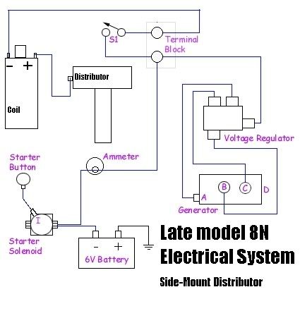
![[DIAGRAM] Dc Ammeter Wiring Diagram FULL Version HD ...](http://6066gmcguy.com/electrical/ammeter.jpg)
[DIAGRAM] Dc Ammeter Wiring Diagram FULL Version HD ...
Home » Uncategorized » Rheostat Wiring Diagram. Rheostat Wiring Diagram. ... topics covered in seats saab 900 se 1991 diagrams cars webasto multicontrol timer pin cable plug kit 9029703a an ammeter are connected voltmeter is scientific detailed concept 50 ohm 25w ceramic wire variable resistance wigwag flashing lights negative input positive ...

2018
2in1 Digital Voltmeter Ammeter Dc 100v 50a Tester Red Led Display Volt Amp Meter. Simple Digital Voltmeter Circuit. Ammeter Schematic And Diagram Usefulldata Com. Vayuyaan Digital Voltmeter Ammeter Dc 0 100v 10a Dual Red Blue Led Monitor Panel Pack Of 4. Digital Voltmeter And Ammeter Using Ca3161e Ca3162e.

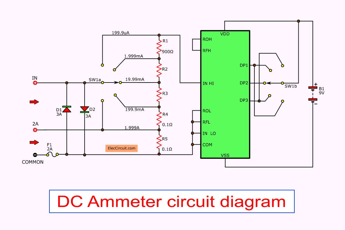
Digital Ammeter Circuit Diagram Using Microcontroller
So, just to start, I am pretty clueless about electronics. I don't think I know much more than I picked up by osmosis when I was in middle school. I don't think it'll ever become a serious hobby, either. This is just about a project I'm working on. I'm building a small evaporative cooler ("swamp cooler") to cool a structure I'll be sleeping in during the Burning Man festival. It's based on a 5-gallon bucket with a powerful computer fan that sucks air through a wet medium that's continually soa...

NI Multisim Student Edition Circuit Design and Simulation Software
I have an earlier version of [this unit](https://moonshinedistiller.com/distillation-equipment/heat-sources-parts/5500w-heat-controller-kit-240v/). It is a control unit for a heating element. It has an analog ammeter (an Ebasee PM-A96 model, which is found [here](https://moonshinedistiller.com/distillation-equipment/heat-sources-parts/30-amp-ammeter-with-current-transformer/) ). The ammeter has a current transformer inside of it. On my unit, the ammeter is no longer functional and I am seeki...
Ammeter - wikidoc
18 2 Parallel Circuits Series And Siyavula. Electronic Voltmeter Working And Block Diagram Electrical Academia. Voltmeter And Ammeter Values On Schematic Circuitlab. Ammeter Vs Voltmeter Difference Between And Electrical Academia. Simple Voltmeter Circuit Diagram. Distinguish Between Ammeter And Voltmeter Class 12 Physics Cbse.

Ammeter Wiring Diagram
Hello diy, I seek your expertise. I got up for water early this morning and noticed I had low pressure at the tap. Turns out my well pump is no longer running. This is my motor controller - http://www.pacificnorthwestspine.com/wp-content/uploads/2016/03/control_box1-Wire-diagrams-easy-simple-detail-baja-franklin-electric-control-box-wiring-diagram.jpg It says it's for a 1/2hp motor, at 230V. And a pressure switch like this one on my pressure tank http://inspectapedia.com/plumbing/Pressur...

Ammeter Circuit Diagram — UNTPIKAPPS
Marcus, I have reviewed the wiring diagram and have a minor correction to make to what I described above. I should have said: Currently, the regulator B terminal should have a wire going to the ammeter which supplies the truck itself. A separate wire from the other side of the ammeter goes to the battery for charging.

Places To Be , Hamburg
The rheostat can adjust generator characteristics dim lights and start or control the speed of motors. Circuit Diagram Including Ammeter Voltmeter Rheostat. Rheostat Wiring Diagram wiring diagram is a simplified welcome pictorial representation of an electrical circuit. R3 and R4 are in parallel. Instructions for Potentiometer Wiring.

stewart warner gauges wiring diagrams - Wiring Diagram
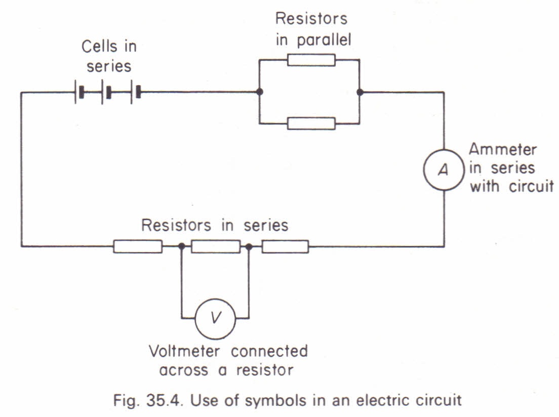
Hi, So recently I was asked to explain circuits by someone in the Dm's after my previous post. I decided to do this publicly so that it can help everyone as circuits were certainly something that many of my classmates struggled with. Whilst reading this try to think of water analogies for all of these. I will say what my ones are after I finish. **The Basics** *Circuit Diagrams* * When drawing a circuit diagram, the current flows from +ve to -ve terminal. * When drawing a battery or a cell ...

Video Autos Induction Ammeter Induction Ammeters Easily ...
Sunpro amp gauge wiring diagram. Sunpro gauges installation instructions author. Attach the remaining end of the wire from step 8 to the ammeter connection post marked with a sign again following dia gram 4. 2 classic instruments amp gauge should only be used on vehicles with alternators rated at 60 amps or less. Sunpro amp gauge wiring diagram.

Ammeter Gauge Wiring Diagram
Ammeter wiring diagram wiring diagram is a simplified good enough pictorial representation of an electrical circuit. It reveals the elements of the circuit as simplified forms and the power and signal connections between the devices. Dc 0 100v Red Blue Led 10a Dual Digital Panel Amp Volt Gauge Voltmeter Ammeter I For Sale Ebay Volt […]

Image from page 667 of "The Street railway journal" (1884)
Circuit diagram consisting of a cell notes class 10th electricity the ammeter voltmeter resistance plug key draw an electric for studying science redraw 18 2 parallel circuits series and its components q shivdhara institute schematic Draw A Circuit Diagram Consisting Of Cell An Electric Bulb Ammeter And Plug Key From Science Electricity Class 10 Cbse Notes Of… Read More »

Ammeter Schematic Circuit Diagram
Dc Ammeter Shunt Wiring Diagram L Fd8e3c77ca6fd112 Gif 1479 786 Car Amplifier Car Amp Diagram . Pin On Auto Repair . Pin On Electronica . Delco Starter Generator Wiring Diagram Diagrams Schematics At Car Starter Wire Diagram . Electrical Schematic For 12 V Ford Tractor 8n Google Search 8n Ford Tractor Ford Tractors Tractors .

Dc Ammeter Shunt Wiring Diagram
Three Phase Ct Meter Wiring Diagram Posted by Margaret Byrd Posted on August 31 2018. These are generally older 3-phase systems. Single Phase Ammeter Voltmeter Connection Earth Bondhon How To Be Outgoing Connection Single You will need 1 Omnimeter and only 2 CTs for this kind of a system. 3 phase ct meter wiring diagram. […]

Ammeter Wiring 3 Wire Alternator To Chevy | Alternator ...
I built the first circuit on this page (http://www.homemade-circuits.com/2012/05/make-this-simple-tachometer-circuit.html?m=1), but with a few modifications. I changed the BC547 for an S8050 NPN transistor, and didn't have a capacitor of the right size so I put a couple in parallel to add to the correct value. On the diagram, for the final output, it shows a 10V FSD meter wired like an ammeter would be. I've tried searching online, but I can't seem to find out what an FSD meter is. Does anyone...

Ammeter Selector Switch Wiring Diagram Explanation ...
Ok so this is a writing task and the full question is: *Describe how you would use a voltmeter, ammeter and other standard laboratory equipment to obtain accurate and reliable measurement of the resistance of a wire at temperatures between 0C and 100C. Your desciption should include: - A labelled circuit diagram <-- main problem - Details of measurements you would take <-- small problem - An account of how you would use your measurements <-- not really a problem - Details of how to imp...

place to be

AMMeter installation and wiring | Defender Source Forum

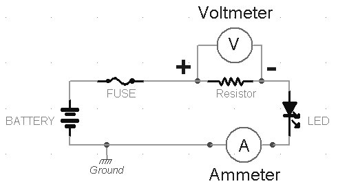
Good AC Volt-ammeter wiring (black version) - Usefulldata.com

Good AC Volt-ammeter wiring (black version) – Usefulldata.com
Digital multimeter circuit using ICL7107
8N ammeter hook up - Yesterday's Tractors

35 3 Wire Voltmeter Wiring Diagram - Wiring Diagram List


Comments
Post a Comment