39 apm 2.8 wiring diagram
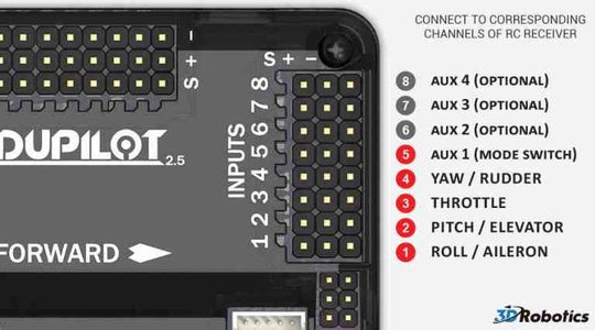
The Pin Configuration of Input side of APM (Which is to be connected to APM) and configuration of Reciever FS-iA6 is as shown. APM 2.5, 2.6, 2.8 all have similar configuiration. Here the outermost pin is Ground, Middle pin is for Positive supply and the innermost pin is Singnal Pin. Ideal way to connect various channels with reciever is also shown. Arducopter 2.8 Wiring. Building Your First ArduCopter: Whether its for kids or youngsters, Drones have If any motor is moving opposite then just reverse the two side wires from esc to . I build my first quadcopter which is the f with apm , but my problem is. For Erle-Brain boards be sure you connect the ESC connector in the right way.
APM Wiring, ESC + Receiver. Posted by Jani Hirvinen on July 15, 2010 at 9:14am. Illustrated cable connections between APM + Receiver, APM + ESC's and motor locations for ArduCopter. + Configuration. Read more….
Apm 2.8 wiring diagram
APM 200 is to be -2 inches of water column; the exhaust interlock switch is preset to trip with an exhaust failure. • Exhaust flow and volumes can be found in the Facility Matrix in Section 3, Installation. 2.8 ELECTRICAL SAFETY The SemiChem APM 200 contains type 3. Other areas of the SemiChem APM 200 may contain type 3 hot work. Turnigy 9x Receiver Wiring. Help! Connecting the Turnigy 9x receiver Multirotor Drone Talk. First, I recommended you try if it works! Connect all channels as you can see in the picture. PPM encoder pinout for sure: INPUT: 1) GND - black. 2) 5V - red. I need to know how to use the channels when connecting the ECS and Servos to a Turnigy 9X Receiver? Arducopter 2.8 Wiring. 25.09.2018. 25.09.2018. 1 Comments. on Arducopter 2.8 Wiring. For APM you can use the supplied APM Power Module for the power. Warning . You still need an ESC Example Wiring Diagram for a Bixler plane with APM. For APM you can use the supplied APM Power Module for the power.
Apm 2.8 wiring diagram. diagrams 3 2.3. circuit diagram instructions, p. 3 drawn part no. date international truck and engine corporation chk rev name this print is provided on a restricted basis and is not to be used in any way detrimental to the interest of international truck and engine corporation. date reference release no. change sheet electrical circuit diagram ... Download scientific diagram | ArduPilot Mega (APM) autopilot: (a) APM 2.8 unit (b) APM 2.8 circuit board. from publication: A Survey on Open-Source Flight ... In this second video in the APM 2.X series we look at how to mount the board, how it's powered, how to install the motors and calibrate the ESCs and perform ... APM 200 is to be -2 inches of water column; the exhaust interlock switch is preset to trip with an exhaust failure. • Exhaust flow and volumes can be found in the Facility Matrix in Section 3, Installation. 2.8 ELECTRICAL SAFETY The SemiChem APM 200 contains type 3. Other areas of the SemiChem APM 200 may contain type 3 hot work.
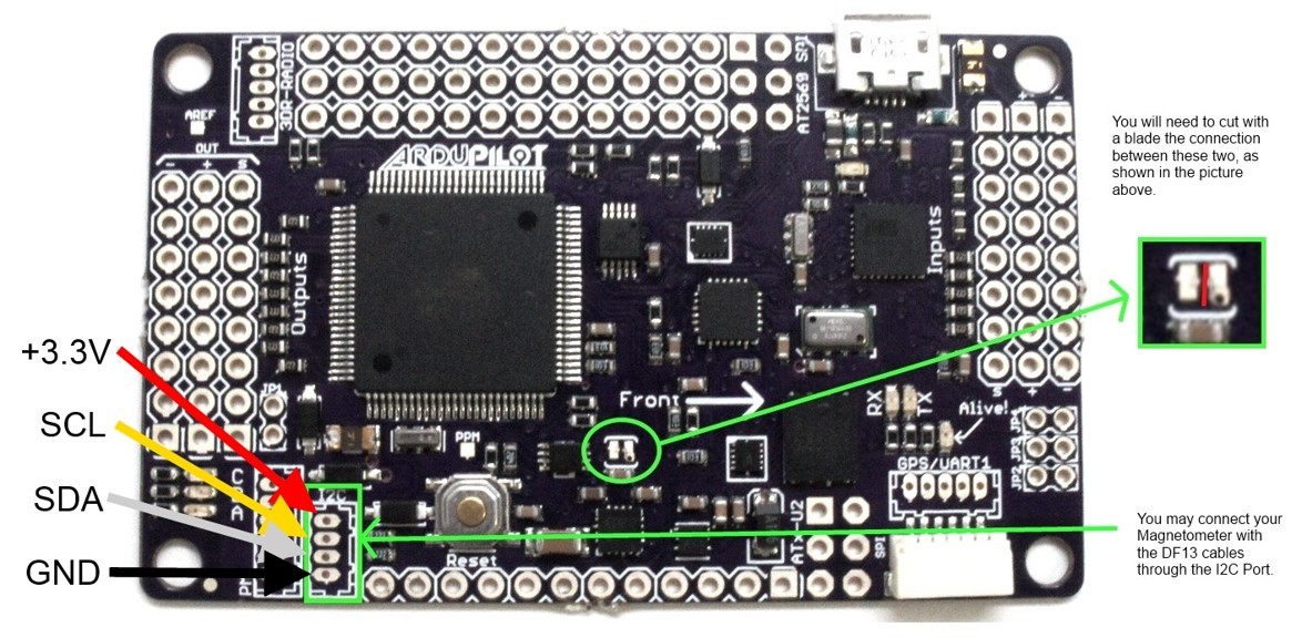
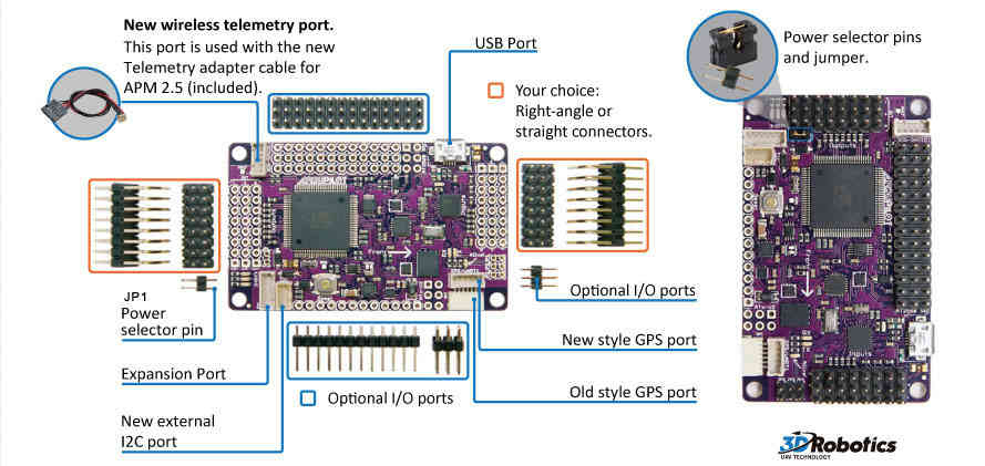
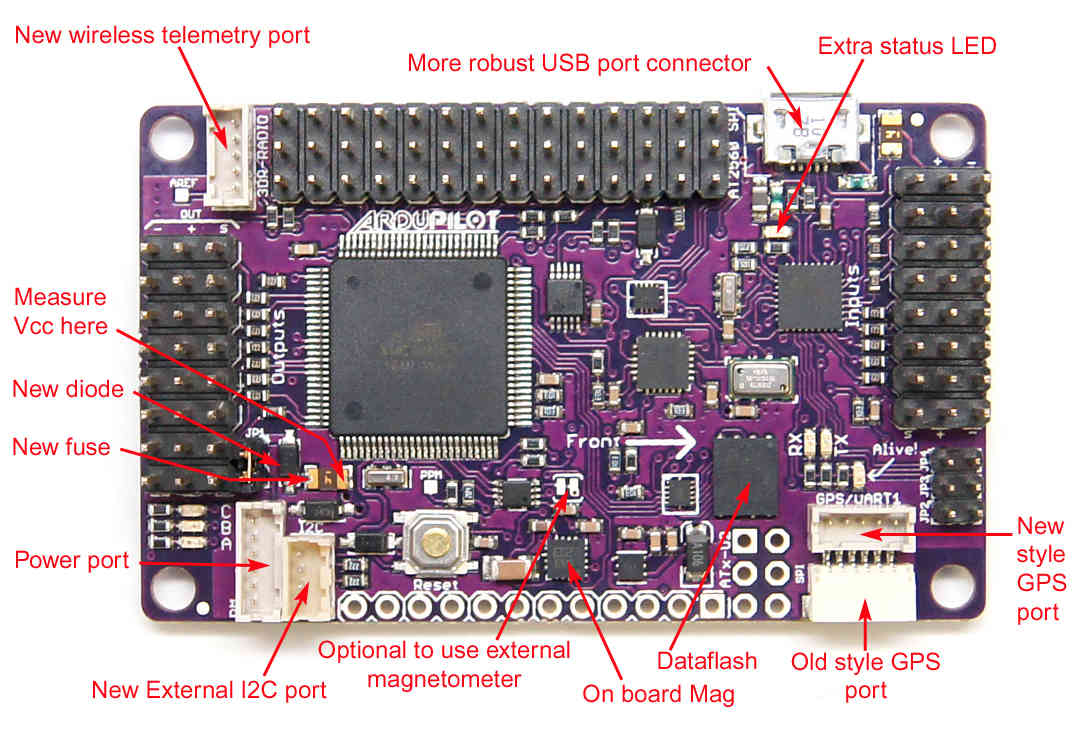
Jun 30, 2016 — I have APM 2.8 Devo 7E tx Devo RX701 receiver mavlink mini OSD ... I have a wiring diagram of my setup, but can't seem to upload it! 39 APM 2.8 Fig.6. (b) Above Fig 6. (b) is shown the APM 2.8 flight controller protection packing. APM 2.8 will contain some of meters which are used to control the vehicle when the it is in air, if don not provide this type of protection to APM 2.8 the drone (quad copter) may be chance to misbehaver with us or irresponsive to our controllers. Mission Planner documentation can be found here. Connect the ArduPilot APM to the computer via USB cable. Open Mission Planner, select the comm port then click "Connect". If not working, go to Device Manager to update driver using driver under Mission Planner folder. Download firmware to the board (don't "Connect" to mission planner). Connecting the optical flow sensor to APMv2. Power, GND, NCS pins should be attached to A3. MISO, MOSI and SCLK pins should be directly soldered to the pins shown above. Default mounting is lens pointing down, pins forward. Its a good idea to secure the wires with some cable ties so they dont break off over time.
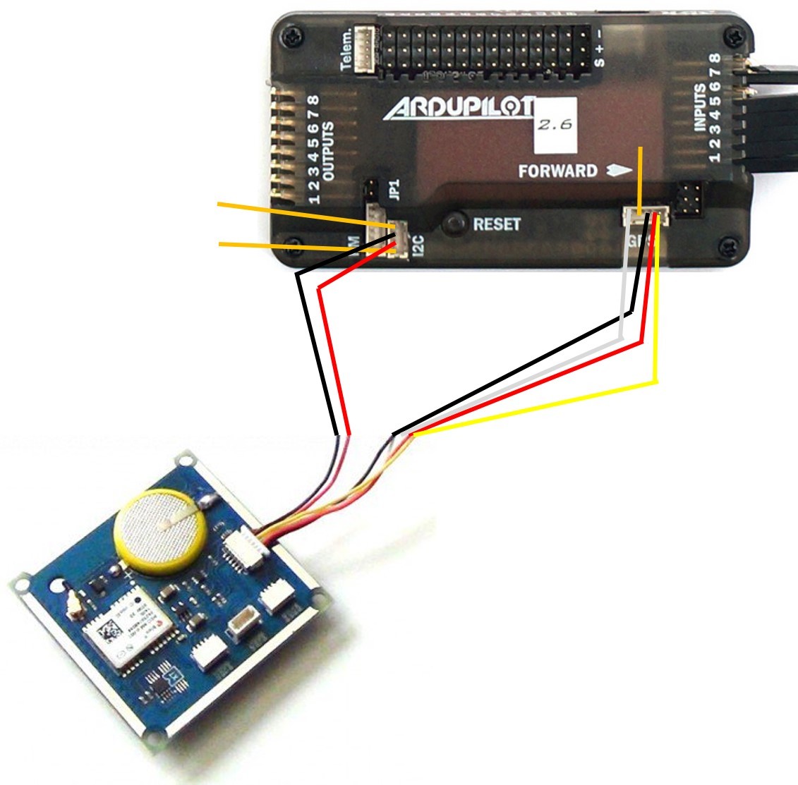
Wiring the 6M Gps with APM. After you have mounted you gps to frame, the next step is to connect it to apm. Connect the two wires of the gps to to the l2c port and the other four wires goes to the gps port on apm. (refer to the picture in part 5) Wiring the ESC'S with APM. You would have four wires from all the esc's(one for each). APM 2.8 and GPS / Compass. I've done lots of thread-searching but haven't found a fix; any help would be appreciated. I am in the process of upgrading from APM 2.5 to APM 2.8. My problem is that I cannot get the GPS / Compass to work. It is (they are) a Ublox Neo module (s). The MAG jumper next to the GPS connector is removed but even with it ... Bosch Type Relay Wiring Diagrams. 2. 3. Arducopter 2.8 Wiring. Building Your First ArduCopter: Whether its for kids or youngsters, Drones have If any motor is moving opposite then just reverse the two side wires from esc to. I build my first quadcopter which is the f with apm , but my problem is. Download >> Download Apm 2.8 manual Read Online >> Read Online Apm 2.8 manual mission planner pdfapm 2.8 motor layout ardupilot flight stack apm 2.8 barometer apm 2.8 manual download apm 2.6 schematic pdf arducopter 2.8 wiring apm 2.8 pinout. texts #pictures #bookmarks #links #videos Ive put together a manual from the Arducopter wiki site for myself and would like to share with the Assembly ...
Discussion Apm Minimosd Telemetry Radio Diagram Rc Groups
Apm Wiring Diagram- wiring diagram is a simplified okay pictorial representation of an electrical circuit.It shows the components of the circuit as simplified shapes, and the capacity and signal associates amongst the devices. A wiring diagram usually gives opinion about the relative aim and conformity of devices and terminals on the devices, to incite in building or servicing the device.
Apm 2 6 Schematic Discussions Diydrones
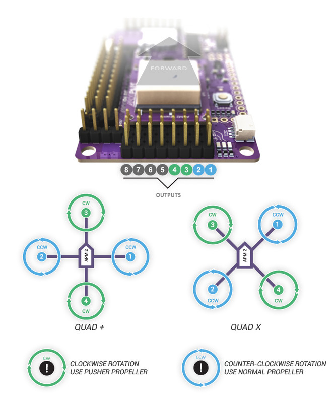
APM Wiring Diagram ¶ The diagram below is an overview of how an APM2 can be connected to a receiver, ESC, GPS and even a camera gimbal. ... Connect the power module to the APM PM port using a 6-position cable. Connect the PDB multi-wire cable to APM Output Signal pins with the M1 wire connecting to the signal pin labeled 1, M6 and signal pin 6 ...
Archived Apm2 X Wiring Quickstart Plane Documentation
92-21354-55-14 supersedes 92-21354-55-13 air-cooled condensing units equipped with the comfort control system™ (-)anl-jez model series - 13 seer (-)apm-jez model series - 14.5 seer

Cx20 252 To Apm 2 8 Wiring For Motors Youtube
X8R to APM 2.8 wiring hookup. Hi guys, first time posting here. I could use some help with wiring my APM 2.8 to a FrSky X8R receiver. I've been searching for what feels like forever on the internet/ YouTube and have details on hooking up everything from a Naze 32 to Pixhawk but nothing for my specific setup.
Connecting Ublox Neo Gps To Apm Guides Dronetrest
Remote Automation Solutions Part Number D301217X012 July 2017 ROC800-Series Remote Operations Controller Instruction Manual ROC809 ROC827
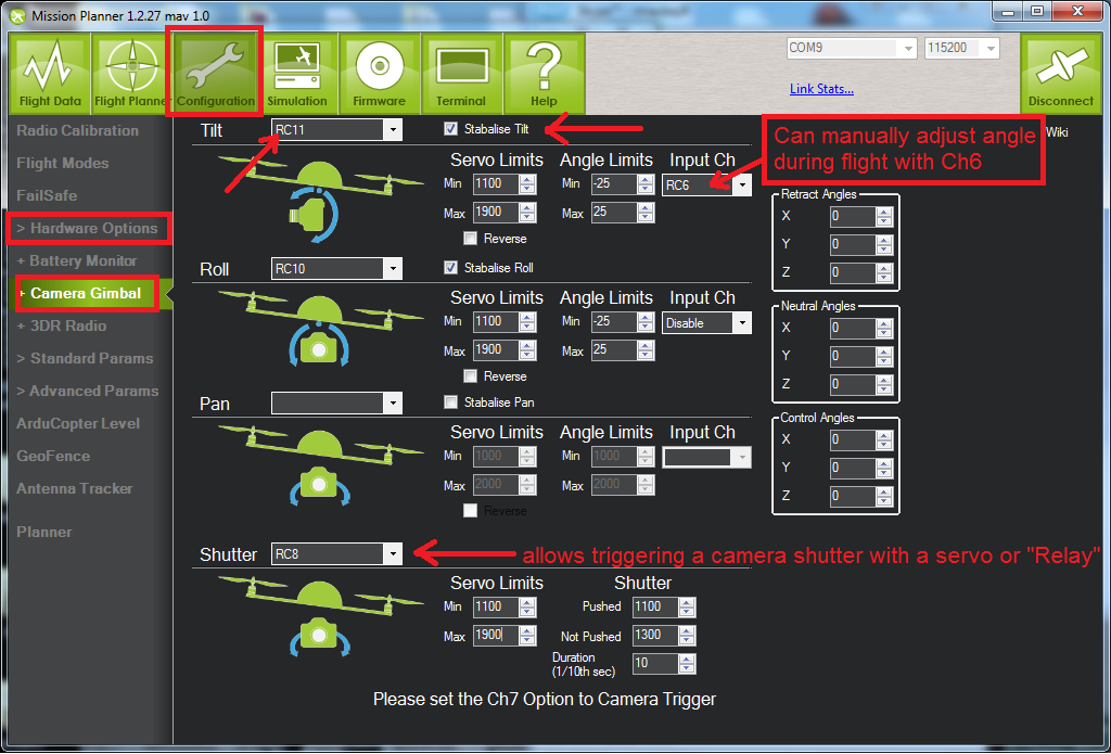
Arducopter Camera Gimbal Setup Using Mission Planner How To Review
2.7.13 Cabling Diagram and Parts List-Track Ball ... Enhanced Micro TDC 3000 User's Manual ii 9/95 2.8 Tower #2 Equipment Cabling 2.8.1 Optional Universal Station Upgrade 2.8.2 Optional Redundant Network Interface Module 2.8.3 Optional Computer Gateway CLI I/O ... (APM) is part of the Enhanced Micro TDCÊ3000 Control System, it is not ...
Apm 2 6 Schematic Discussions Diydrones
30 Lovely Peterbilt Starter Wiring Diagram- Your starter went out and you want to replace it: Here's what to do:First you craving to acquire the out of date ...

Apm 2 6 Ardupilot Flight Controller Gps 100mw 3dr Radio Telemetry 915mhz Minimosd Current Sensor 3dr Radio Telemetry 915mhz 3dr Radio Telemetryradio Telemetry Aliexpress
APM 2.8 wiring (camera switch, OSD, VTX, step down, UBEC) Hello guys, I have been researching this stuff for a couple of months now and decided to look into my specific build a little more, I just want to know your inputs on my setup and if I am missing something. (I don't want to blow up my APM)

The Cube User Manual V1 0 Cubepilot
Consider supporting the channel by visiting www.patreon.com/painless360See my playlist for all the videos in the series - https://www.youtube.com/playlist?li...

My First Diy Quadcopter F450 Quadcopter With Ardupilot Flight Controller F450 With Apm 2 8 Quadcopter Kit Guide About Ho Quadcopter Diy Quadcopter Diy Drone
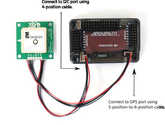
3DR GPS uBlox with Onboard Compass includes two connector cables: one 4-position cable and one 5-position-to-6-position cable. To connect the GPS module to APM 2.6, connect the GPS to the APM GPS port using the 5-position-to-6-position cable; connect the GPS to the APM I2C port using the 4-position cable.

Apm 2 8 Multifunction Flight Controller Board With M8n Gps Built In Compass For Fpv Rc Multicopter Drone Flight Control Board Apm 2 8controller Board Aliexpress
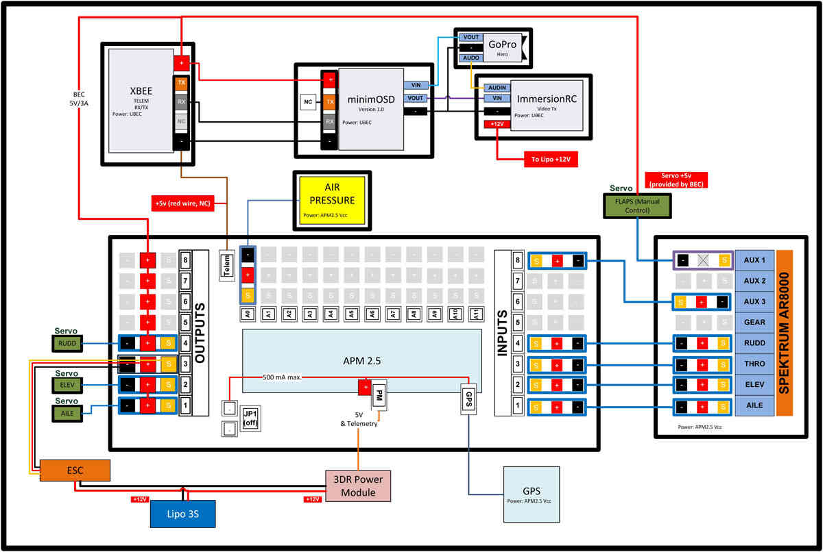
Here is an example wiring diagram how components in a drone are connected to a flight controller. ... theres a github site. wiring is simple; 5 v, g, rx from openlager to free tx on FC. ... but I am building a quad 450 and I am thinking on the APM 2.6, AM 2.8 or the OpenPilot CC3D Revolution Revo 10DOF STM32F4.
Apm 2 6 Schematic Discussions Diydrones
Apm 2.8 Wiring Diagram 27.11.2018 5 Comments Auto Pilot RC Drone - ArduPilot APM ArduPilot APM Connect the ArduPilot APM to the computer via USB cable. APM Wiring Diagram. The diagram below is an overview of how an APM2 can be connected to a to APM Output Signal pins with the M1 wire connecting to the signal pin labeled 1.
Archived Apm2 X Wiring Quickstart Plane Documentation
Xem ngay 65 cửa hàng bán apm 2 8 Chính hãng Giá rẻ nhất. Nơi mua apm 2 8 Uy tín Bảo hành tốt nhất Cập nhật tháng 12/2021 ở Toàn quốc Hồ Chí Minh (TP.HCM - Sài gòn) Hà Nội
Compass Stability Problems Neo 7m On Apm 2 8 Discussions Diydrones
I have apm 2.8 and ublox neo 6m gps without compass module, many of the experts and sites says that neo 6m gps is not compatible with apm 2.8. Can you please explain it to me or help me in getting it work as it is actually not recognised by apm 2.8 while I am trying it.
%20APM2.8-KIT4/s-l1600-700x700.jpg)
Index Of Image Cache Data Multirotor Flight Control System I ˆ5 Apm2 8 Kit4
Arducopter 2.8 Wiring. 25.09.2018. 25.09.2018. 1 Comments. on Arducopter 2.8 Wiring. For APM you can use the supplied APM Power Module for the power. Warning . You still need an ESC Example Wiring Diagram for a Bixler plane with APM. For APM you can use the supplied APM Power Module for the power.

Wiring Diagram Unidtgcontrollerboard Unidtg
Turnigy 9x Receiver Wiring. Help! Connecting the Turnigy 9x receiver Multirotor Drone Talk. First, I recommended you try if it works! Connect all channels as you can see in the picture. PPM encoder pinout for sure: INPUT: 1) GND - black. 2) 5V - red. I need to know how to use the channels when connecting the ECS and Servos to a Turnigy 9X Receiver?

Connecting Apas T1 Soil Moisture And Temperature Sensor To Arduino Part 1 Hardware
APM 200 is to be -2 inches of water column; the exhaust interlock switch is preset to trip with an exhaust failure. • Exhaust flow and volumes can be found in the Facility Matrix in Section 3, Installation. 2.8 ELECTRICAL SAFETY The SemiChem APM 200 contains type 3. Other areas of the SemiChem APM 200 may contain type 3 hot work.

Apm 2 5 Minimosd V1 1 How To Setup W Gopro 3 B Flite Test
Archived Apm 2 5 And 2 6 Overview Copter Documentation
Archived Apm 2 5 And 2 6 Overview Copter Documentation

F14586 7 Apm2 8 Apm 2 8 Build In Compass Apm2 6 2 6 No Compass Flight Controller 2 For Diy Fpv Rc Drone Multicopter Apm 2 8 Apm2 6 Flight Controlapm 2 6 Flight Controller Aliexpress

Ardupilot Update Apm Firmware Compass Calibration Battery Voltage Airspeed Xuav Mini Talon Part 6 Youtube

Cinestar 8 W Apm2 5 Full Diagram And Questions Diy Drones Updated Diy Drone Diagram Drone
Arducopter Quickstart Guides And Tips Arduino Based Arducopter Uav The Open Source Multi Rotor
Building Your First Arducopter 9 Steps With Pictures Instructables

Pin On Electronics Circuit
3

1 Pcs Lot Apm 2 8 Upgraded Multicopter Flight Controller Directnine Europe

Ardupilot Mega Apm Autopilot A Apm 2 8 Unit B Apm 2 8 Circuit Board Download Scientific Diagram

Button To Control Relay And Update Ui Questions Wled

Buy Apm2 8 Ardupilot Flight Controller Neo 6m Gps Compass 915mhz Telemetry Module At Affordable Prices Free Shipping Real Reviews With Photos Joom

Ublox Gps Compass Module Copter Documentation

Arducopter Quickstart Guides And Tips Arduino Based Arducopter Uav The Open Source Multi Rotor
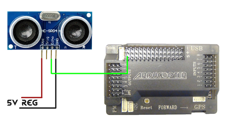
Hc Sr04 Sonar Apm 2 8 Multirotors Ardupilot Discourse
1

Rc Airplane Uav
Archived Apm2 X Wiring Quickstart Plane Documentation

Airplane Ardupilot Wiring Diagram Raspberry Pi Px4 Autopilot Airplane Electronics Electrical Wires Cable Airplane Png Pngwing
Connecting Ublox Neo Gps To Apm Guides Dronetrest


Comments
Post a Comment