39 physical network diagram vs logical
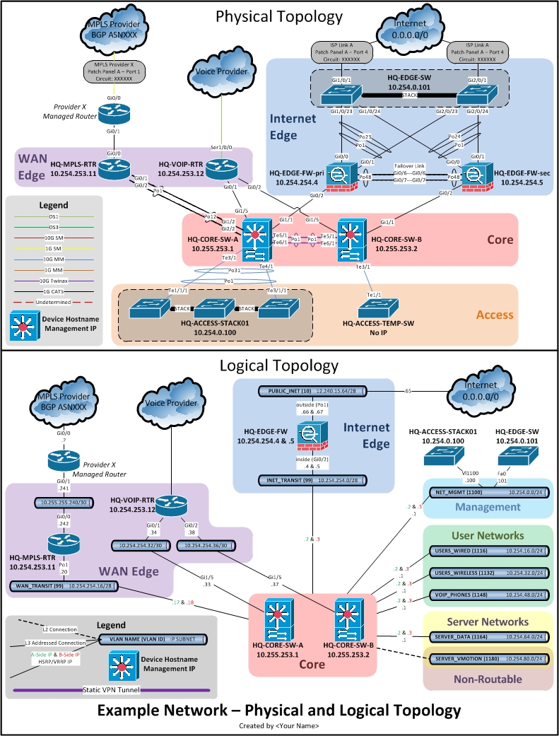
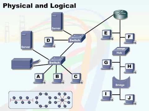
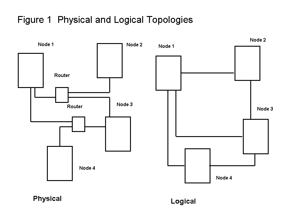
As illustrated in Figure 1.12, this makes the physical structure considerably different from the logical structure of a network. Figure 1.12 Logical Structure vs. Physical Structure The Logical Structure consists of Forests, Domain Trees, Domains, Organizational Units, and Objects Network topology types are usually represented with network topology diagrams for convenience and clarity. There are two types of network topology: physical and logical. Physical topology describes how network devices (called computers, stations, or nodes) are physically connected in a computer network.
It also helps to determine the logical structure of a database. The most popular example of a Database model is the Relational Model, which consists of table format. There are various types of database models like Network, Object, Document, etc. Logical and Physical Database Models are also a part of it.
Physical network diagram vs logical
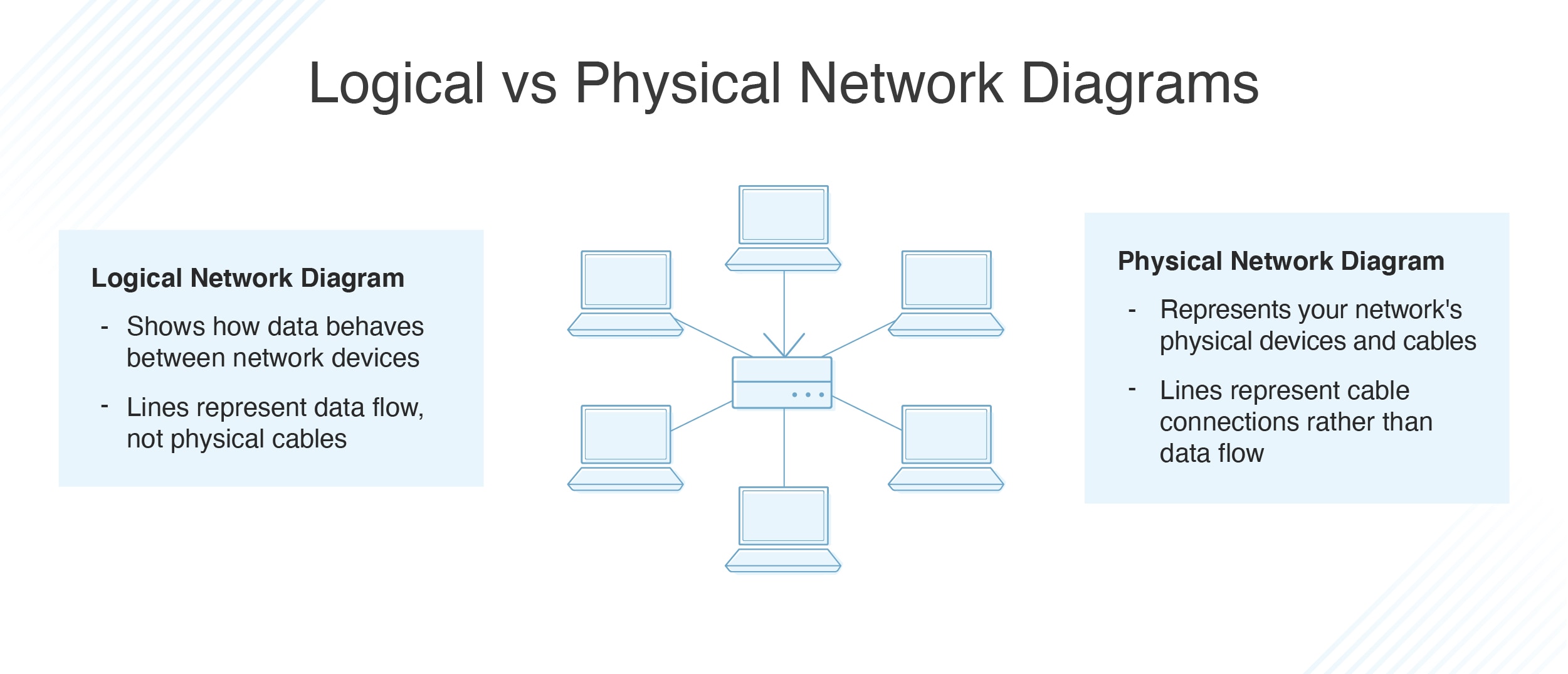
With a network topology diagram, you can gain valuable visual insight into the logical and physical layouts of your network, enabling admins to view connections between components during troubleshooting activities. Overall, the arrangement of a network can have a significant impact on your network's connectivity, availability, and functionality. Every logical and physical detail matters, and it's best to see those details in relation to each other as a diagram. Networks are the backbone of both modern and legacy architecture alike, and it's the spanning of those two generations of systems that a Network Architect has to obsess over. Logical vs. Physical Network Diagram Logical Network Diagram Physical Network Diagram The logical network diagram shows how the data behaves and flows between the devices in a network. The physical network diagram is what its name shows. This type of network diagram shows you the physical devices and the cables connected.
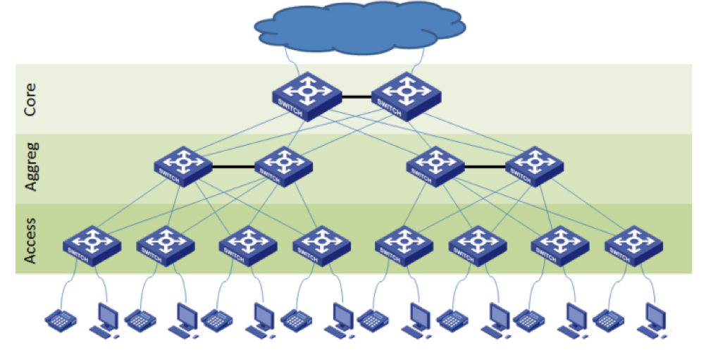
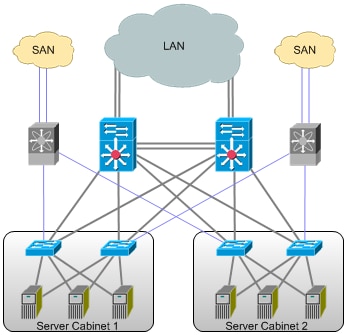
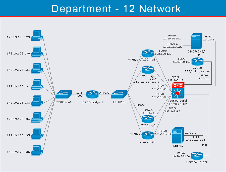
Physical network diagram vs logical. Two main types of network topologies in computer networks are 1) Physical topology 2) Logical topology. Physical topology: This type of network is an actual layout of the computer cables and other network devices. Logical topology: Logical topology gives insight's about network's physical design. Different types of Physical Topologies are ... Logical and Physical Addresses in an Operating System. A logical address is generated by CPU while a program is running. Since a logical address does not physically exists it is also known as a virtual address. This address is used as a reference by the CPU to access the actual physical memory location. A physical network diagram is similar to a floorplan, giving you insight into the actual arrangement of your network's tangible elements. What Is a Logical Network Diagram? Logical network diagrams, on the other hand, represent how data moves through the network. Network Diagram. The network diagram should illustrate logical network separation and communication within your network devices such as routers, firewalls, nodes and other hardware (both virtual and physical) located within your environment. The network diagram is a living document that is updated and reviewed regularly for accuracy.
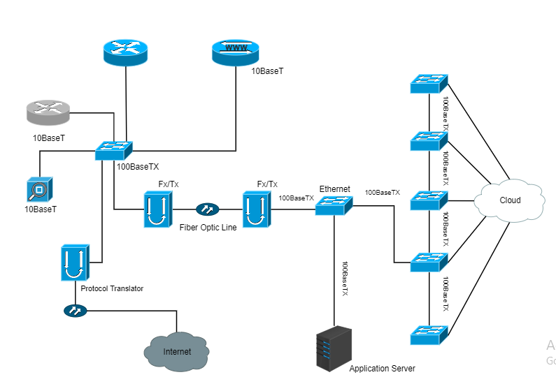
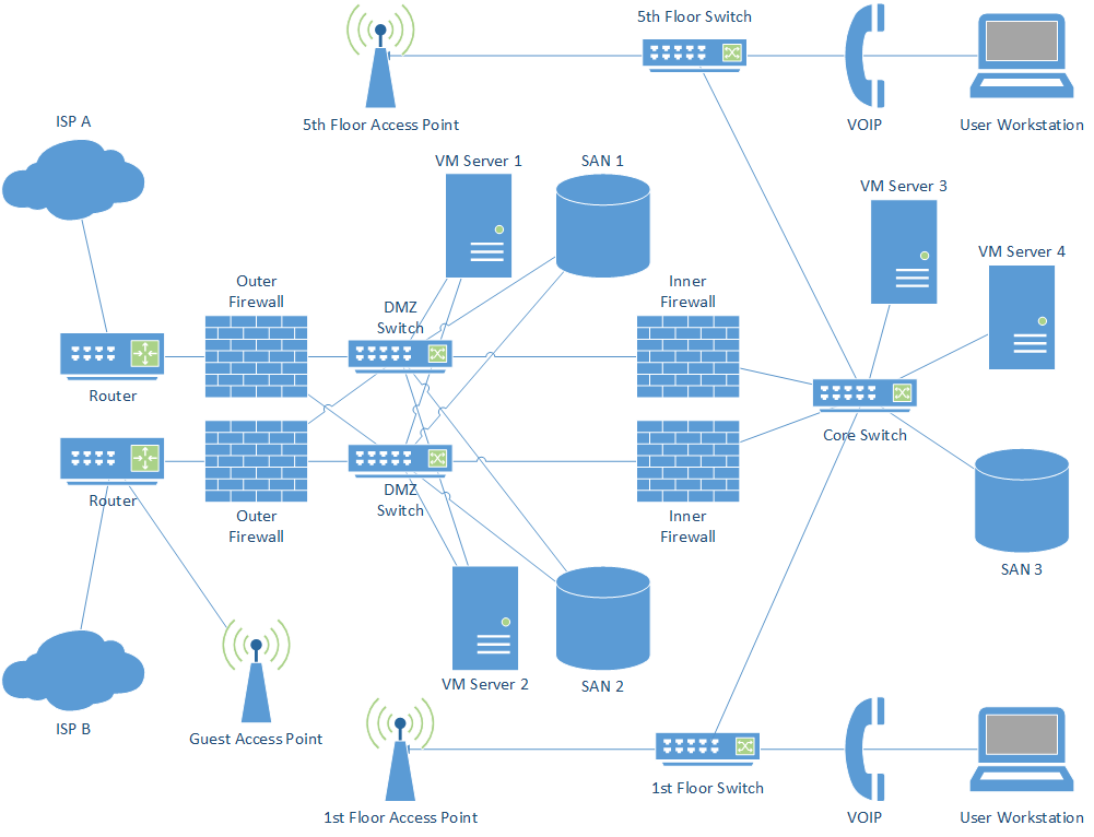
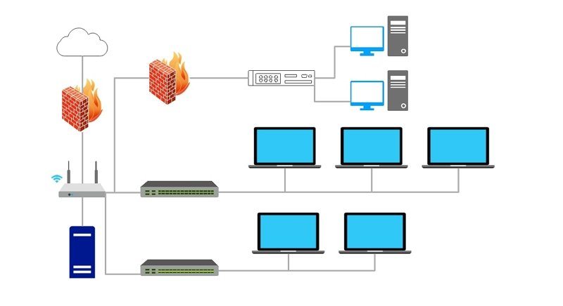
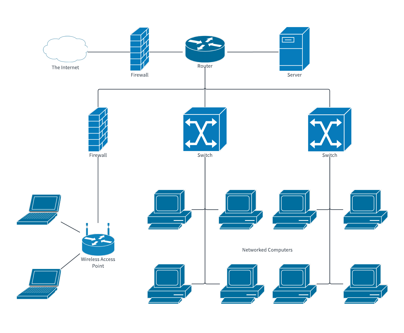
So when looking at physical network diagrams, you will often see devices like firewalls, switches, routers, and access points, along with a representation of the physical connections between them. Layer 2 is the logical layer of the OSI model. Logical network diagrams represent network topologies at higher levels. Jul 30, 2020 — Logical vs. Physical Network Diagrams · provide a picture of how your networks operate · help identify network objects, such as routers, firewalls ... Logical network diagrams are focused less on the physical hardware and applications on a network and more on how and why everything connects the way it does. A logical network diagram typically includes information about subnets, routing protocols, and hardware like firewalls and routers that show how data flows from place to place. Prerequisite : Physical and Logical Data Independence. 1. Physical Data Independence : The physical data independence is basically used to separate conceptual levels from the internal/physical levels. It is easy to achieve physical data independence. With this type of independence, user is able to change the physical storage structures or the ...
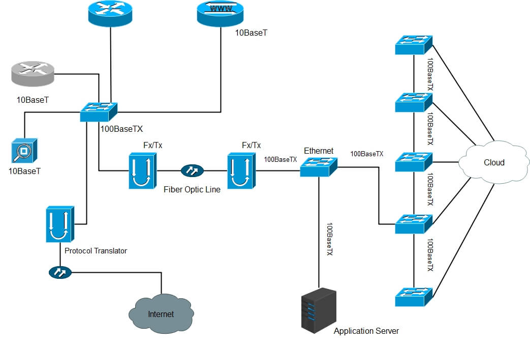
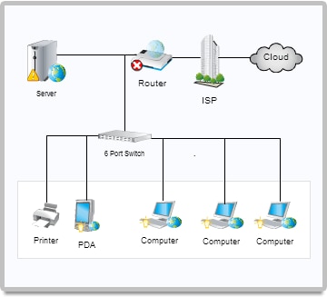
The physical network diagram uses wired signals, whereas the logical network diagram uses wireless communication. The physical network diagram shows the physical connection and representation of devices like routers, switches, access points and firewalls. A logical network diagram uses subnets, routing protocols, and network devices. Since there's no significant difference between those two models except the number of details shown on the diagram, they can both be modeled using a logical diagram. Depending on the details you've added to your model using the logical diagram, you make the model more "conceptual" or more "logical". A physical network diagram shows the actual physical arrangement of the components that make up the network, including cables and hardware. Typically, the ... The external network adapter can be bound to one of the following physical network adapter configurations: The external network adapter can be bound to a single underlying physical network adapter. In this configuration, an extensible switch extension is exposed to and manages only one underlying network adapter on the host.
Network Topologies Logical Vs Physical Aruba Blogs
Logical Address Space is the set of all logical addresses generated by CPU for a program whereas the set of all physical address mapped to corresponding logical addresses is called Physical Address Space. The logical address does not exist physically in the memory whereas physical address is a location in the memory that can be accessed physically.

Logical And Physical Network Diagram There4travelg7
It consists of physical topology and logical topology. Physical topology describes the physical layout of the network while logical topology defines data flows on the physical layout. If you like this tutorial, please share it with friends via your favorite social networking sites and subscribe to our YouTube channel.
7 Best Network Diagram Software Free Guide Dnsstuff
While the diagram will include similar nodes as seen in a physical network diagram, like servers, routers, and switches, the lines represent data flow rather than physical cabling. Admins may create multiple logical network diagrams, including maps to describe their WAN, LAN, AWS, Cisco, and other environments.

Network Diagram Guide Learn How To Draw Network Diagrams Like A Pro
A network diagram can help you observe the logical aspects of your network as well as its physical elements. Logical Network Diagrams Logical network diagrams display the inner behaviors of your network, such as routing protocols and subnets, and reveal how information flows through a network.

Physical And Logical Network Diagrams Jobs Ecityworks
The physical address is a label that identifies a particular section of the memory unit. It is actually available on the memory unit. Whereas, the logical address is used as a reference to the physical address which helps us in accessing the physical address. The logical address is generated by the CPU, unlike the physical address.

What Is A Network Diagram Dcim Network Documentation Osp Software
Network diagrams can be of two types. Physical: This type of network diagram showcases the actual physical relationship between devices/components which make the network. Logical: This type of diagram shows how the devices communicate with each other and information flows through the network. It is mostly used to depict subnets, network devices ...

فرسان الحاسب Logical Network Diagrams
Physical Address. This address is a location in the memory unit. This address is a set of all physical addresses that are mapped to the corresponding logical addresses. The user can't view the physical address of program directly. It is computed using MMU. The user can indirectly access the physical address.
Network Documentation Series Logical Diagram
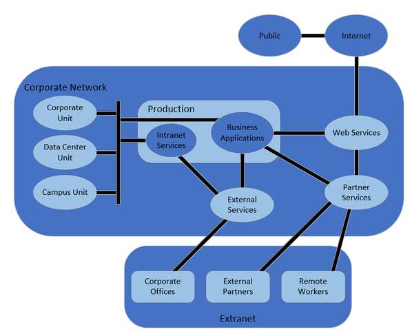
In short, the logical architecture of microservices doesn't always have to coincide with the physical deployment architecture. In this guide, whenever we mention a microservice, we mean a business or logical microservice that could map to one or more (physical) services. In most cases, this will be a single service, but it might be more.

How To Draw Clear L3 Logical Network Diagrams Packet Pushers
Physical topology defines how the systems are physically connected. It represents the physical layout of the devices on the network. The logical topology ...

The Logical And Physical Networks Download Scientific Diagram
A physical data model is usually derived from a logical data model for a particular relational database management system (RDBMS), thus taking into account all technology-specific details. One big difference between logical and physical data models is that we now need to use table and column names rather than specifying entity and attribute names.
Network Diagram Software How To Use Switches In Network Diagram Lan Topology Diargam Network Switch Computer Lab
Logical and physical network diagrams are important because they can provide comprehensive overviews of networks. In diverse environments, it can be challenging ...

Difference Between Physical And Logical Topology Youtube
Irrespective of how sophisticated they are, network diagrams can either be logical or physical. This categorization concerns how various devices are arranged in a network. Logical Network Diagrams. These are the most commonly used diagrams by network administrators since these diagrams provide information about the flow of data in a network.
Network Topology Diagram Definition And Types Edrawmax
A physical network diagram illustrates the interconnection of the devices in the network with wires and cables. In contrast, the logical network diagram ...4 answers · 7 votes: A logical network diagram usually shows network devices like routers, firewalls, and voice gateways. ...

It And Network Knowledge Sharing Lan Network Topologies
Logical: A logical network diagram describes the flow of data. Logical diagrams are focused on software — subnets, network objects, external programs, routing protocols, domains, and traffic flow are just some of the elements that might be included in a logical diagram. Physical: A physical diagram describes connected hardware, rather than ...
7 Best Network Diagram Software Guide Solarwinds
Physical Network Diagram Template Create physical and logical network designs using network and computer equipment shapes, and map Web sites. Examples of Physical Network Diagrams The physical network diagram is created by the administrator to represent the physical layout of the network. The diagrams are the most vital document needed to ...

Network Diagram Templates And Examples Lucidchart Blog
A physical network diagram illustrates the interconnection of the devices in the network with wires and cables while a logical diagram Illustrates the way ...

Physical Network Design Process Define The Logical Architecture How Many Nodes Are On The Network What Types Of Nodes Physics Topology Networking
Logical vs. Physical Network Diagram Logical Network Diagram Physical Network Diagram The logical network diagram shows how the data behaves and flows between the devices in a network. The physical network diagram is what its name shows. This type of network diagram shows you the physical devices and the cables connected.
148 13 Topologies 03 Physical And Logical Youtube
Every logical and physical detail matters, and it's best to see those details in relation to each other as a diagram. Networks are the backbone of both modern and legacy architecture alike, and it's the spanning of those two generations of systems that a Network Architect has to obsess over.

Logical Network Diagram Quickly Create Professional Lan Diagram Lan Drawing
With a network topology diagram, you can gain valuable visual insight into the logical and physical layouts of your network, enabling admins to view connections between components during troubleshooting activities. Overall, the arrangement of a network can have a significant impact on your network's connectivity, availability, and functionality.
Logical Security Architecture Daniel Pratt

Logical Network Diagram Template Lovely Hyper V Network Multitenant Network Free Transparent Png Clipart Images Download

Logical Network Diagram Ppt Video Online Download

Shows An Example That Explains The Relationship Between Physical And Download Scientific Diagram
A Survey Of Computer Network Topology And Analysis Examples
Network Diagram Examples Free Download Edrawmax

Physical Network Diagrams Explained Dcim Network Documentation Osp Software

7 Best Network Diagram Software Guide Solarwinds

Logical Vs Physical Network Diagrams Dcim Network Documentation Osp Software
3

A Network Topology Is The Arrangement Of A Network Including Its Nodes And Connecting L Networking Infographic Software Architecture Diagram Networking Basics

Network Documentation Series Logical Diagram

What Is A Network Diagram
The Physical Network Diagram Explained Edrawmax Online
Logical Vs Physical Network Diagrams Dnsstuff

Hotel Network Topology Diagram

Logical Vs Physical Network Diagrams Dcim Network Documentation Osp Software
Network Diagrams Jose Rodriguez
The Physical Network Diagram Explained Edrawmax Online
How To Draw A Network Diagram Edrawmax Online


Comments
Post a Comment