39 system sensor duct detector wiring diagram
Wiring Diagrams 5-7 Warranty8 BEFORE INSTALLING Read the System Sensor Guide for Proper Use of Smoke Detectors in Duct Applications (HVAG53), which provides information on detector spacing, placement, zoning, wiring, and special applications. This manual is available online at www.systemsensor.ca. CAN/ULC S524 should also be referenced SuperDuct duct smoke detectors will not sense smoke unless the ventilation system is operating and the sensor's cover is properly installed. SuperDuct duct smoke detectors may not operate as designed unless the duct detector is installed in accordance with these instructions and all applicable national and local codes as
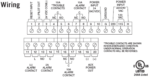
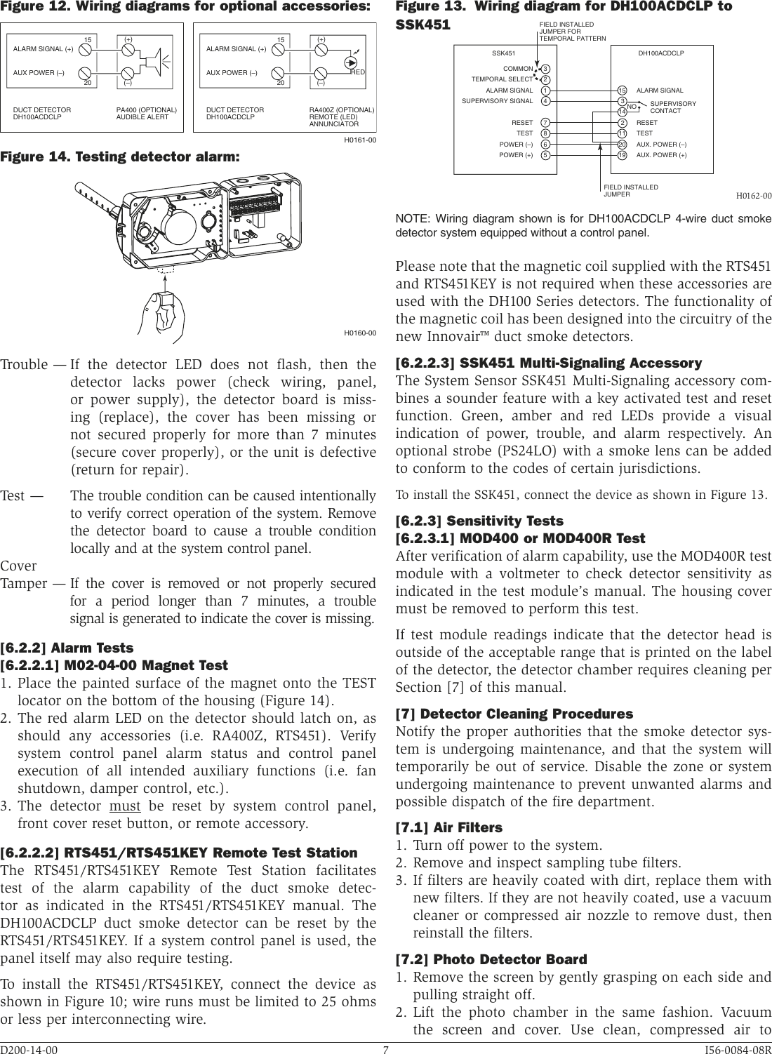
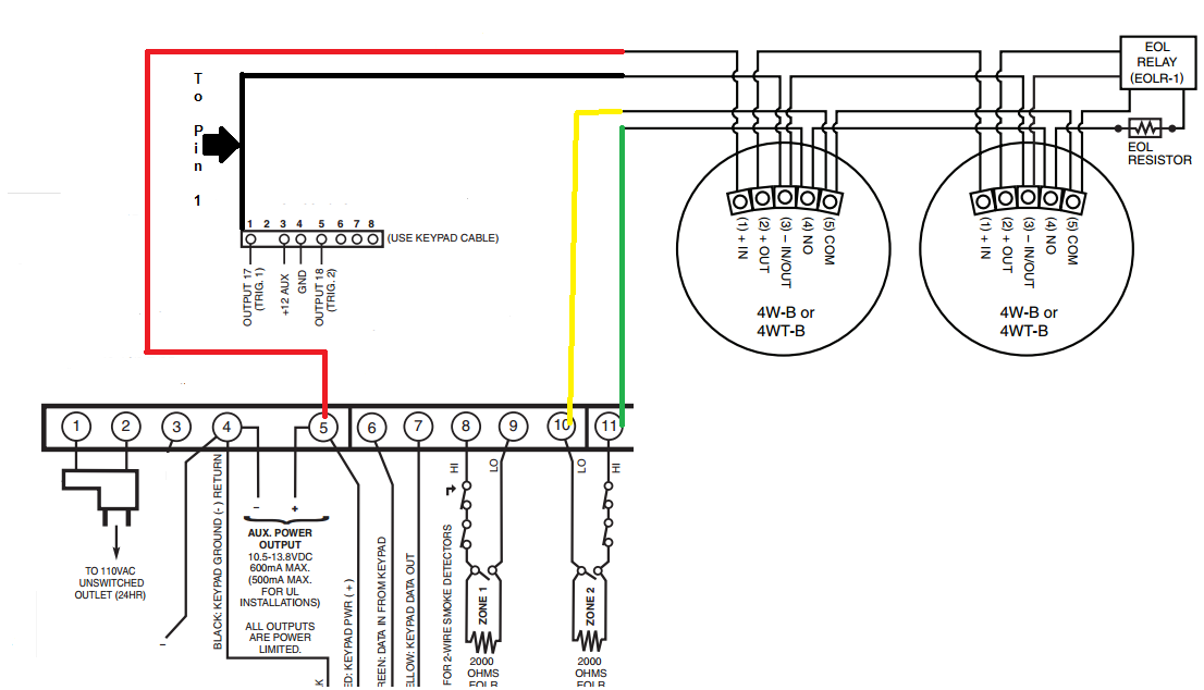
Wiring for 2-wire Duct Smoke Detector System wiring diagram for 2-wire duct smoke detectors powered from initiating device circuit. 24 V AC 10 15 FULL W AVE RECTIFIED UNFIL TERED. System sensor duct detector wiring diagram. Wiring diagram shown is for DH100ACDCLP 4-wire duct smoke detector system.

System sensor duct detector wiring diagram
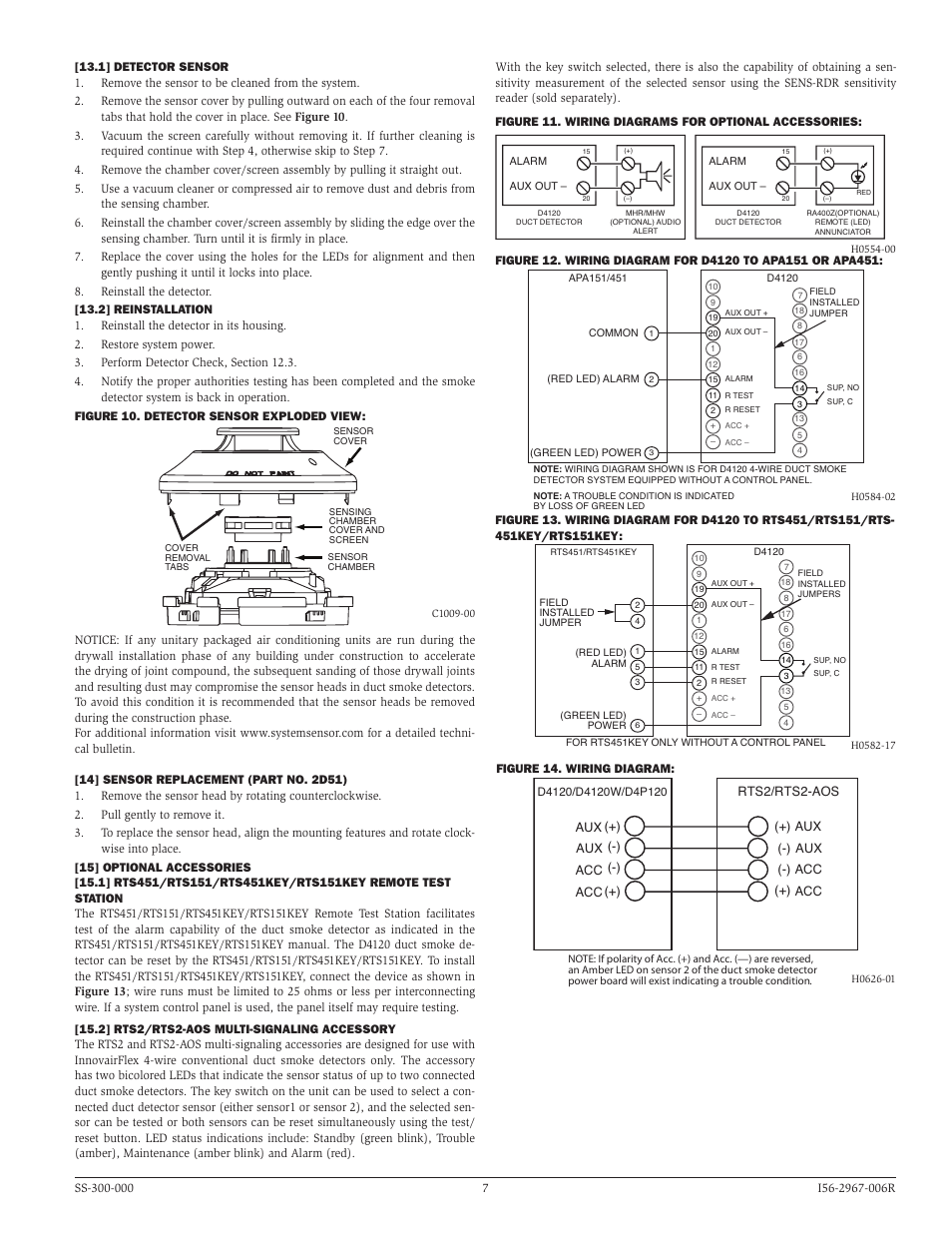
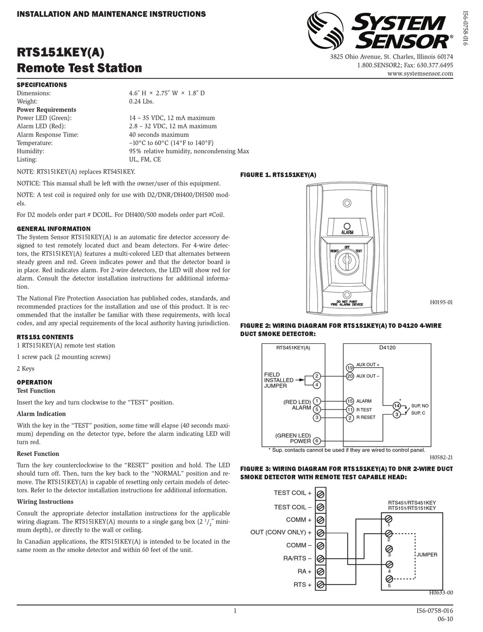
Duct Smoke Detector The System Sensor DUCTSD Series duct smoke detectors with a cover integrated smoke test port and fl exible confi gurations provides effi cient installation and maintenance. Features • 4-Wire Photoelectric, integrated low-flow technology • Air velocity rating from 100 ft/min to 4,000 ft/min (0.5 m/s to 20.32 m/sec) resetting only certain System Sensor models of detectors. Refer to detector installation instructions for additional information. Figure 2: Wiring diagram for RTS451 to DH100ACDC 4-Wire Duct Smoke Detector Figure 3: Wiring diagram for RTS451 to DH100 2-Wire Duct Smoke Detector 15 20 2 11 2 Alarm Signal + 1 Aux. Power - Reset Test (Red LED) Alarm Read System Sensor's Applications Guide for Duct Smoke Detectors (HVAG53), which provides information on detector spacing, placement, zoning, wiring, and special applications. This manual is available online at www.systemsensor.com. NFPA Standards 72 and 90A should also be refer-enced for detailed information.
System sensor duct detector wiring diagram. Read the System Sensor Guide for Proper Use of Smoke Detectors in Duct Appli- cations (A05-1004), which provides detailed information on detector spacing, placement, zoning, wiring, and special applications. Series™. 4-Wire Duct System Sensor DHACDC 4-wire duct housing will Wiring Diagram for.System wiring diagram for duct detectors using a UL listed control panel (see Figure 9 for wiring of optional accessories): CAUTION Do not loop wire under terminals when wiring detectors. Break wire runs to provide system supervision of connections. The System Sensor Innovair™ DH100ACDCI is a 4-wire ionization air duct smoke detector capable of sensing smoke in air velocities from 500 to 4,000 feet per minute (2.54 to 20.32 m/sec). System Sensor D duct smoke detectors - 4-wire photoeletric smoke duct sensor head offers improved false alarm immunity and simple installation, testing . GENERAL INFORMATION System Sensor's RTS is an automatic fire detector WIRING DIAGRAM FOR RTS TO D 4-WIRE DUCT SMOKE.Also note that the System Sensor D is the replacement for the DHACDCLP.
System Sensor Duct Detector Wiring Diagram | Wiring Diagram - Duct Smoke Detector Wiring Diagram. Wiring Diagram not only provides in depth illustrations of whatever you can do, but also the processes you should stick to whilst doing so. Not just is it possible to locate various diagrams, however, you can also get step-by-step guidelines for ... Refer to the applicable figures below depending on your duct housing model number. 2. With all wiring in place, install the detector head. 3. Energize the duct detector. Wiring must conform to applicable local codes, ordinances and regulations covering these types of devices. Wire the detectors according to the engineering drawings for the Hvac Duct Smoke Detector Wiring Diagram. Sl 2000 duct smoke detector hvac talk heating air refrigeration weatherproof ionisation universal voltage detectors wire detection nfpa 90a 4 low profile dn 60267 notifier and nx 8 edwards superduct conventional two. Firex 2650 761 Photoelectric 115 230 Vac Universal Voltage Duct Smoke Detectors. The System Sensor Innovair™ DH100ACDCLP is a 4-wire photoelectric air duct smoke detector capable of sensing smoke in air velocities from 100 to 4,000 feet per minute (0.5 to 20.32 m/sec). This Innovair features Low-Flow technology that enables duct smoke detection throughout a broad range of air-flow environments.
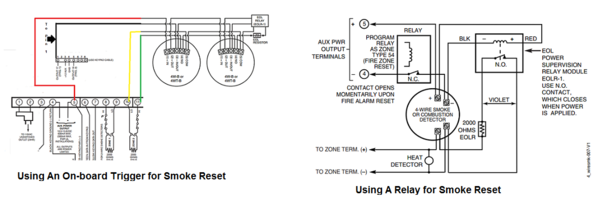
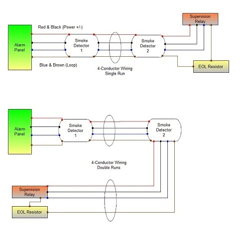
on the back of the sensor head. SS-300-021. 4. I56-3538-002R. FIGURE 6. SYSTEM WIRING DIAGRAM FOR DNRE:. Smoke introduced into an air duct system will be distributed throughout the entire building. Smoke detectors designed for use in air duct systems are used to sense the presence of smoke in the duct. Model D4120 and D4S Duct Smoke Detectors utilize 4-wire photoelectric technology for the detection of smoke. This detection method, when com- SYSTEM WIRING DIAGRAM FOR D2E 2-WIRE DUCT SMOKE DETECTORS WITH NEGATIVE SUPPLY (–) SUPERVISION (DETECTORS. POWERED FROM INITIATING CIRCUIT):. NOTE: FOR POSITIVE ... The answer is, each duct detector would go into alarm, however only the wiring/circuit would be monitored for integrity. If you do not wire the resistor through each of the detectors supervisory contacts, you are not monitoring the status of the detector itself. An example would be: you have three System Sensor D4120 duct detectors on a single ...
Dh100acdclp Air Duct Smoke Detector With Extended Air Speed Range Pdf Free Download
Duct Smoke Detector Wiring Diagram Download. Assortment of duct smoke detector wiring diagram. A wiring diagram is a simplified traditional photographic depiction of an electric circuit. It reveals the elements of the circuit as streamlined shapes, and also the power and also signal connections between the devices. A wiring diagram typically gives details regarding the loved…

System Sensor D4120 Duct Detectors Connected The Right Way Fire Alarms Online
Smoke introduced into an air duct system will be distributed throughout the entire building. Smoke detectors designed for use in air duct systems are used to sense the presence of smoke in the duct. Model DUCTSD Duct Smoke Detectors utilize 4-wire photoelectric technology for the detection of smoke. This detection method, when combined with an

System Sensor Dh Series Duct Detector To Rts151 Wiring Testing And Explanation Youtube
System Sensor warrants its enclosed air duct smoke detector to be free ... System wiring diagram for 4-wire duct smoke detectors:.4 pages
Firex 2650 761 Photoelectric 115 230 Vac Universal Voltage Duct Smoke Detectors
Smoke introduced into an air duct system will be distributed throughout the entire building. Smoke detectors designed for use in air duct systems are used to sense the presence of smoke in the duct. Model D4120 and D4S Duct Smoke Detectors utilize 4-wire photoelectric tech-nology for the detection of smoke. This detection method, when combined

Duct Detectors Smoke Detection Nfpa 90a Code Quality
Read the System Sensor Guide for Proper Use of Smoke Detectors in Duct Applications (A05-1004), which provides detailed information on detector spacing, placement, zoning, wiring, and special applications. Copies of this manual are available online at www.systemsensor.ca. CAN/ULC S524 should also be referenced for detailed information.
2
Read System Sensor's Applications Guide: Duct Smoke Detectors (HVAG53), which provides detailed information on detector spacing, placement, zoning, wiring ...
2
vided sheet metal screws to screw the duct detector to the duct. CAUTION: Do not overtighten the screws. [4] FIGURE 1. EXPLODED VIEW OF DUCT SMOKE DETECTOR COMPONENTS: MAGNET TEST LOCATION SENSOR MODULE COVER TERMINAL HOUSING MODULE COVER SAMPLING TUBE EXHAUST TUBE SENSOR HEAD WIRING TERMINALS (sold seperately) H0574-06 2 I56-3050-008R 06-10
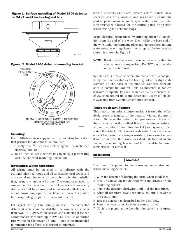
System Sensor 1400 Manual I56 0279
System Sensor Innovair Dh200pl Installation And Maintenance Instructions Manual Pdf Manualslib. Innovairtm intelligent duct detectors series d4120 smoke detector system sensor innovair dh100acdcp users wiring diagrams d2 dh100acdclp air figure 14 testing alarm 4 wire ionization photoelectric low profile flow installation instruction systemsensor a5190 dh200pl dh200rpl user 2 model d2e non ...
System Sensor D4120 D4p120 And D4s User Manual Page 7 8
System Sensor DHACDC 4-wire duct housing will accommodate either the System Wiring Diagram for DHACDC 4-Wire Duct Smoke Detectors Using. System Sensor's DHACDC duct detector can be used either as part of a fire detection system with a control panel or as a stand-alone duct smoke detector.
1
Read the System Sensor Guide for Proper Use of Smoke Detectors in Duct Appli- cations (A05-1004), which provides detailed information on detector spacing, placement, zoning, wiring, and special applications.

Dh100acdclp Air Duct Smoke Detector With Extended Air Speed Range Pdf Free Download
Wiring Guide System wiring diagram for 4-wire duct smoke detectors Wiring diagram for DH100ACDCLP to SSK451: 15 19 14 3 20 1 3 Alarm Signal 2 Aux. Power + Sup. N. O. Sup. COM Aux. Power - NOTE: Wiring diagram shown is for DH100ACDCLP 4-wire duct smoke detector system equipped without a control panel. Alarm (Red LED) Power (Green LED) Common ...

4 Wire Smoke Detector Wiring Tech Resource Online
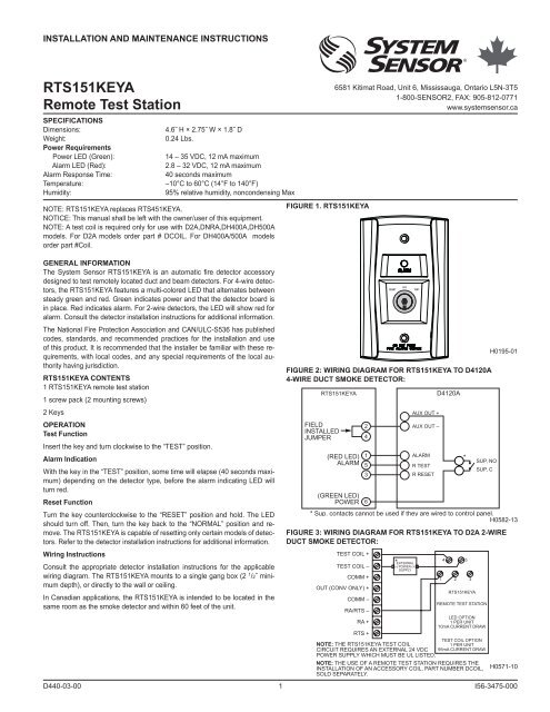
Wiring diagram for 2-wire duct smoke detector to RTS151/RTS151KEY Remote Test Station 3825 Ohio Avenue • St. Charles, IL 60174 Phone: 800-SENSOR2 • Fax: 630-377-6495
System Sensor Dh100acdclp Users Manual I56 0084 08r
The air duct smoke detector shall be a System Sensor InnovairFlex™ D4120 Photoelectric Duct Smoke Detector. The detector housing shall be UL listed per UL 268A specifically for use in air handling systems. The flexible housing of the duct smoke detector fits multiple footprints from square to rectangular.

Home Run 4 Wire Smoke Detectors And Nx 8 Doityourself Com Community Forums
SuperDuct Conventional Two-Wire Duct Smoke Detector 5 6 to 10 duct widths 1 duct width Bend or other obstruction Airflow • For detection of smoke in the supply air system, install the duct smoke detector in the supply air duct at a point downstream from the supply fan and air filters
System Sensor Dnr Duct Detector What Is This Symbol R Firealarms
Built-in short-circuit protection from operator wiring errors ... The air duct smoke detector shall be a System Sensor InnovairFlex™ D4240 Photoelectric ...
How Do I Wire A 4 Wire Smoke Detector To My Wired Alarm System Alarm Grid
System Sensor Smoke Detector Wiring Diagram Download. system sensor smoke detector wiring diagram - A Novice s Guide to Circuit Diagrams An initial appearance at a circuit representation could be confusing, however if you could read a metro map, you could read schematics. The objective is the very same: obtaining from factor A to direct B. Literally,…
System Sensor Rts151key Installation And Maintenance Instructions Pdf Download Manualslib
Read System Sensor's Applications Guide for Duct Smoke Detectors (HVAG53), which provides information on detector spacing, placement, zoning, wiring, and special applications. This manual is available online at www.systemsensor.com. NFPA Standards 72 and 90A should also be refer-enced for detailed information.
Troubleshooting Smoke Alarm Wiring At The Detectors
resetting only certain System Sensor models of detectors. Refer to detector installation instructions for additional information. Figure 2: Wiring diagram for RTS451 to DH100ACDC 4-Wire Duct Smoke Detector Figure 3: Wiring diagram for RTS451 to DH100 2-Wire Duct Smoke Detector 15 20 2 11 2 Alarm Signal + 1 Aux. Power - Reset Test (Red LED) Alarm
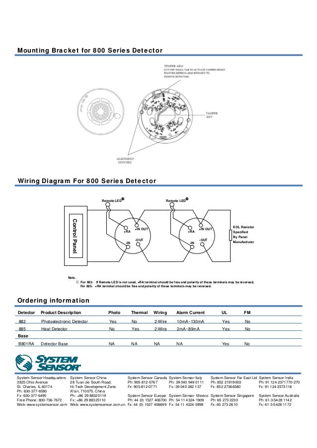
Fire Alarm Photoelectric Smoke Fixed Temperature Heat Detector
Duct Smoke Detector The System Sensor DUCTSD Series duct smoke detectors with a cover integrated smoke test port and fl exible confi gurations provides effi cient installation and maintenance. Features • 4-Wire Photoelectric, integrated low-flow technology • Air velocity rating from 100 ft/min to 4,000 ft/min (0.5 m/s to 20.32 m/sec)

System Sensor Rts151 User Manual Page 2 2
Installation Instructions System Sensor Canada
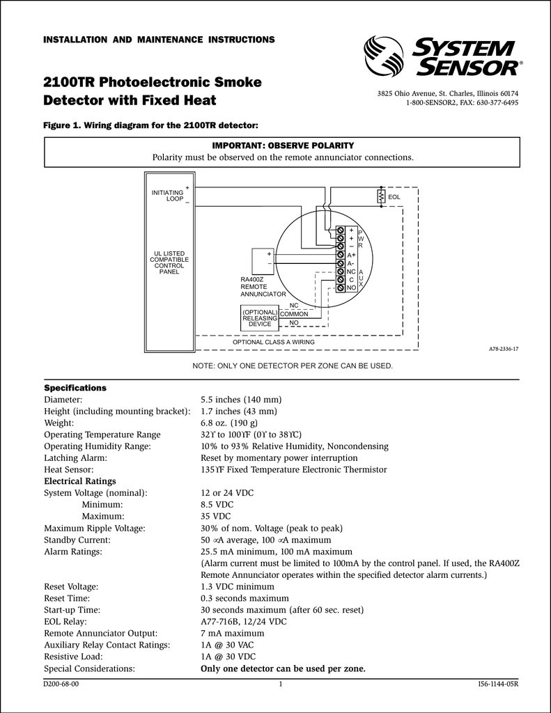
Systemsensor 2100tr
How Do I Install A 4 Wire Smoke On My Vista P System Alarm Grid

System Sensor D4120 Duct Detectors Connected The Right Way Fire Alarms Online

D4120 Products System Sensor System Sensor
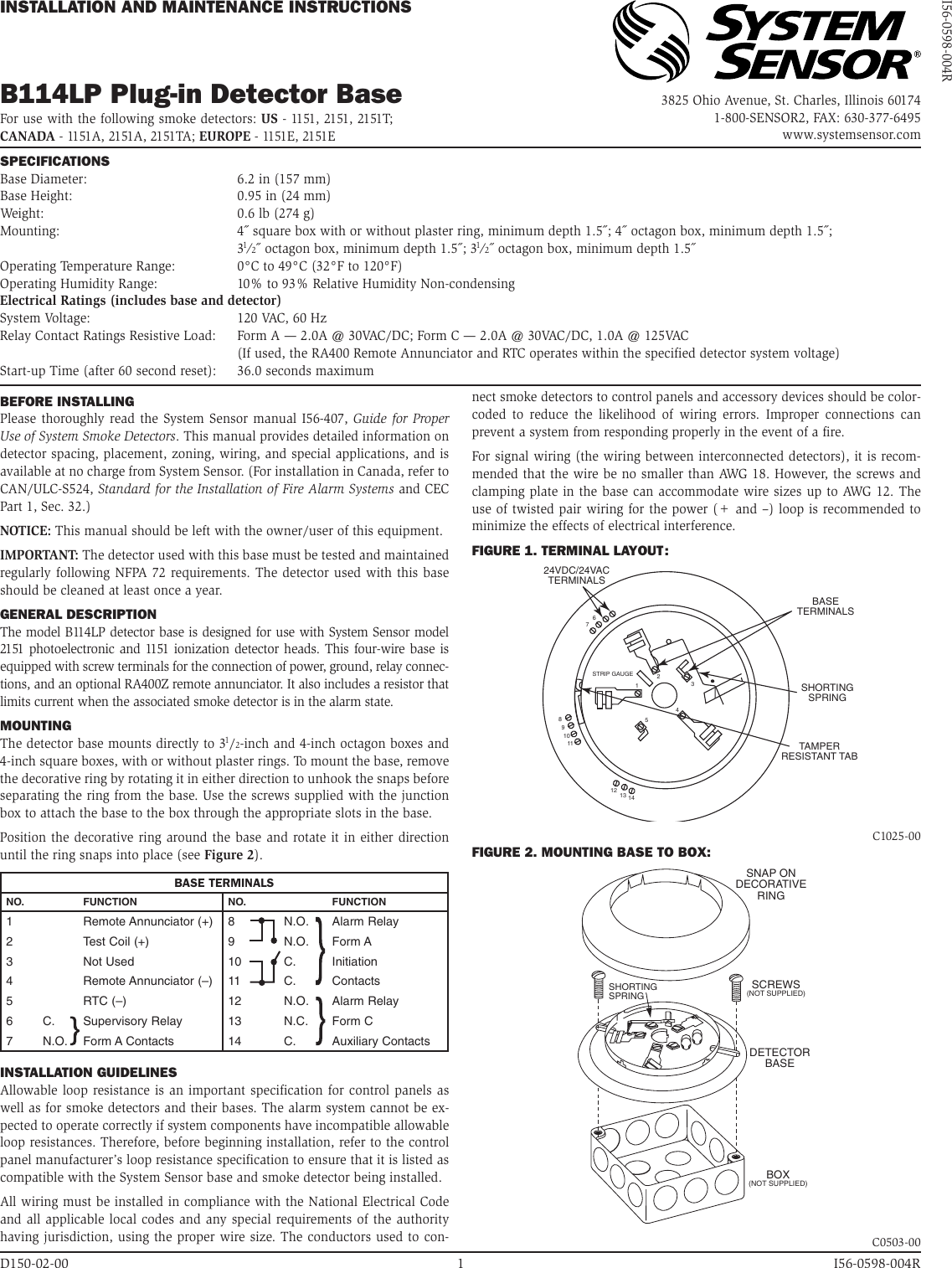
System Sensor B114lp Users Manual

System Sensor Dh100acdclp Low Flow Duct Smoke Detector
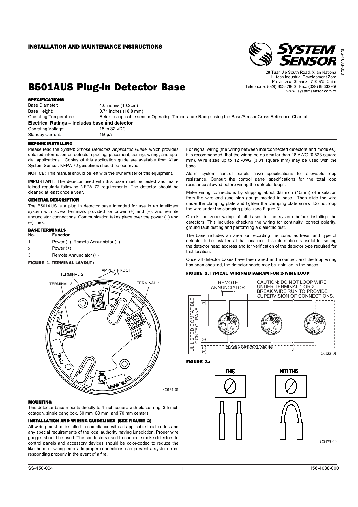
B501aus Detector Base Installation Sheet Manualzz

Comfortable New System Sensor Dnrw Intelligent Non Relay Duct Smoke Detector Fire Alarm 80 Off Www Eyeboston Com

Rts151key A Remote Test Station System Sensor
2
Hvac Talk Heating Air Refrigeration Discussion
Troubleshooting Rtu Duct Smoke Detector Youtube
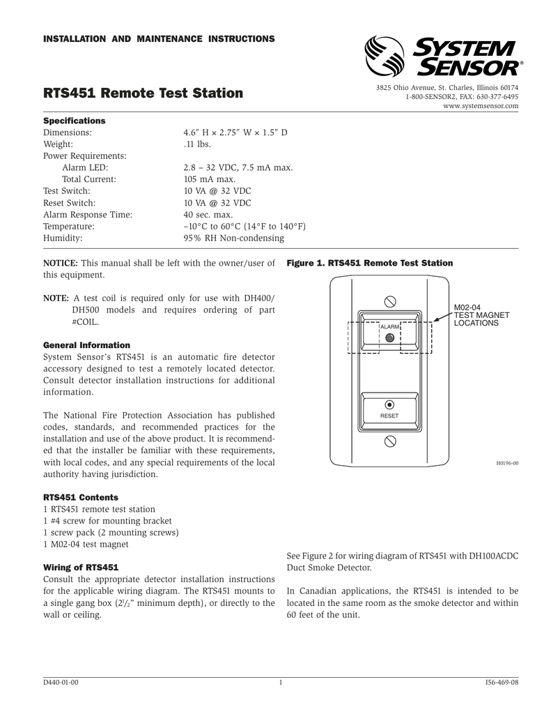
System Sensor Rts451 Installation And Maintenance Instructions Manualzz
Systemsensor Ca

D4120 Products System Sensor System Sensor
2
Smoke Detector Wiring Diagram Electrical Wires Cable Fire Alarm System Sensor Png Clipart Alarm Device

Weatherproof Photoelectric Duct Smoke Detector Sdd 3000 P


Comments
Post a Comment