42 rankine cycle on ph diagram
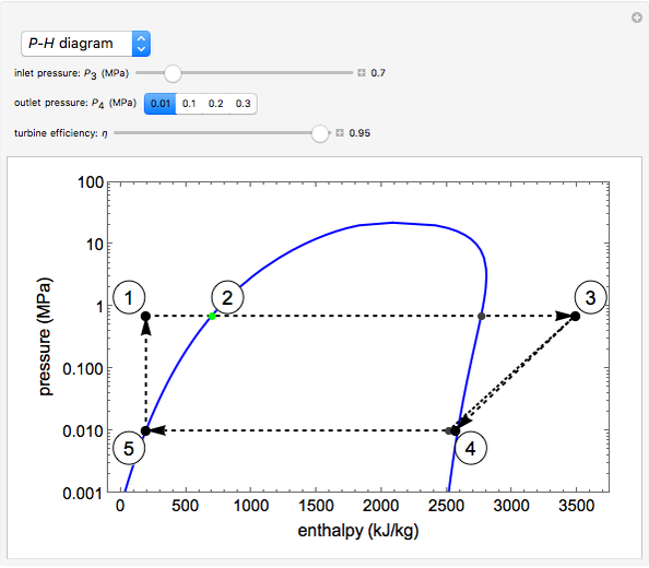
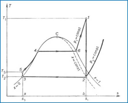
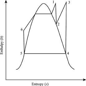
The Rankine cycle is a modified form of Carnot cycle, in which the isothermal compression (3-4) is continued unit the steam is condensed into water. A Carnot cycle, using steam as a working substance, is represented or p-v and t-s diagram as shown in the figure. Consider 1kg of water at pressure P1 and absolute temperature T1 as represented by ... The irreversible turbine pathway is the dashed black line on the diagram; the reversible turbine pathway is the orange dashed line. Select "Rankine cycle" to view a schematic of the cycle, and select "turbine" to show the inlet and outlet conditions for the turbine and the work generated.
He was a founding contributor, with Rudolf Clausius and William Thomson, to the science of thermodynamics, particularly focusing on the first of the three thermodynamic laws. • The Rankine cycle is a cycle that converts heat into work. The heat is supplied externally to a closed loop, which usually uses water.
Rankine cycle on ph diagram
R134a Refrigerant Ph Chart. Enthalpy diagram of thermodynamic cycle p h diagram showing the refrigeration p h diagram thermodynamics hvac and thermodynamic scope for two phase fluid lab 3 ph diagram 1 et 102 p h. Pressure Enthalpy Chart Of Rankine Cycle With R134a For First Se Scientific Diagram. T-s Diagram of Lowering the Condenser Pressure : In a simple Rankine cycle, heat is added to the cycle during process 2-2'-3 (see the T-s diagram on the left). During this first stage (process 2-2'), the temperature of the water is low. That reduces the average temperature during heat addition (process 2-2'-3). Ideal Rankine Cycle (a) Schematic representation of an ideal Rankine cycle (b) T-s diagram of an ideal Rankine cycle . Application of the First law of thermodynamics to the control volume (pump, steam generator, turbine and condenser), gives . Work done on pump, per kg of water, W P = h 2-h 1 . Energy added in steam generator, q 1 = h 3-h 2
Rankine cycle on ph diagram. The Rankine cycle is named after the William John Macquorn Rankine professor at Glasgow university. Rankine Cycle Definition It is defined as a cycle, where heat energy is supplied to the system via the boiler where the fluid typically water is converted to high pressurized steam, and the steam is passed over the turbine and the work is generated. Describes a Rankine power cycle with steam using a log pressure versus enthalpy diagram. A simulation that contains this log P vs H diagram is found here: ht... Bruce G. Miller, in Clean Coal Engineering Technology, 2011 7.1.1 Rankine Cycle. The Rankine cycle is the basis of all large steam power plants, as briefly discussed in Chapter 6 (refer to Figure 6.16).In coal-fired power plants, high-temperature, high-pressure steam is produced by converting the chemical energy stored in the coal into thermal energy and transferring the energy to the working ... The Rankine cycle is an ideal cycle if water passes through the four components without irreversibilities and pressure drops. The ideal Rankine cycle consists of the following four processes, as shown on the T-s diagram on the left: 1-2: Isentropic compression in a pump.
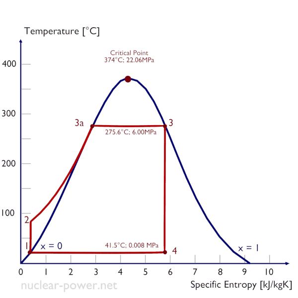
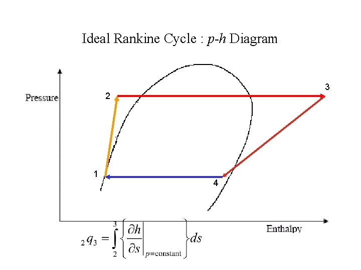
Figure 1 shows the idealized Rankine cycle. The pressure-enthalpy (p-h) and temperature-entropy (T-s) diagrams of this cycle are given in Figure 2. The Rankine cycle operates in the following steps: 1-2-3 Isobaric Heat Transfer. High pressure liquid enters the boiler from the feed pump (1) and is heated to the saturation temperature (2). An Ideal Rankine High Pressure (15MPa) Steam Power Cycle. This is shown below as an Ideal Rankine cycle, which is the simplest of the steam power cycles. We have specifically split the turbine into a High Pressure (HP) turbine and a Low Pressure (LP) turbine since it is impractical for a single turbine to expand from 15MPa to 10kPa. T-s diagram of the Rankine Cycle 2.1. Limitations and Optimization The work and the efficiency of the ideal Rankine cycle can be assimilated to the work and the efficiency of an equivalent Carnot cycle working between the mean hot temperature (i.e. in the boiler) and the condensing temperature, as indicated in Figure 3 entropy diagrams of the simple organic Rankine cycle with R245fa as the working fluid are shown in Figures 2 and 3, respectively. The temperature-entropy diagram includes the heat source (AB) to identify potential pinch-point ... PH diagram of recuperated ORC cycle Figure 6. TS diagram of recuperated ORC cycle
Rankine Cycle Efficiency. Rankine cycle is a condensation process where steam is to be condensed into water.. Rankine cycle is nothing but a modification of Carnot cycle.Ideal Rankine cycle is very useful in steam power plants and gas power plants. To improve the efficiency of Rankine cycle in the steam power plant, there are some changes in Rankine cycle which differs from the Carnot cycle. Download scientific diagram | P-h Diagram for ORC cycle. from publication: Design of heat exchanger to evaporate for R134a working fluid in organic Rankine ... The Rankine cycle is an idealized thermodynamic cycle describing the process by which certain heat engines, such as steam turbines or reciprocating steam engines, allow mechanical work to be extracted from a fluid as it moves between a heat source and heat sink.The Rankine cycle is named after William John Macquorn Rankine, a Scottish polymath professor at Glasgow University. 3. Heat transfer in the ideal Rankine Cycle relies on phase change, a very efficient way to store and release energy. The working fluid is usually water/steam. During the cycle, the properties of the working fluid change as below with associated heat/work exchanges. h (kJ/kg) P (kPa) T (oC) s (kJ/kg-k) q or w (kJ/kg) 1Æ2 Small increase h1 = hf ...
Solved 3 Please Consider An Ideal Rankine Cycle With Co As Chegg Com
A T-s diagram is the type of diagram most frequently used to analyze energy transfer system cycles. This is because the work done by or on the system and the heat added to or removed from the system can be visualized on the T-s diagram. Similarly, what is critical point in Rankine Cycle? Actual Rankine Cycle. 1-2-b-3-4-1.
Rankine Cycle
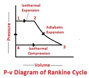
Rankine cycle - Ts diagram. The Rankine cycle is often plotted on a pressure-volume diagram (pV diagram) and a temperature-entropy diagram (Ts diagram).. When plotted on a pressure-volume diagram, the isobaric processes follow the isobaric lines for the gas (the horizontal lines), adiabatic processes move between these horizontal lines, and the area bounded by the complete cycle path ...

Untitled Page
The steps in the Rankine Cycle as shown in Figure 1 and the corresponding steps in the pressure volume diagram (figure 2) are outlined below: . Pump: Compression of the fluid to high pressure using a pump (this takes work) (Figure 2: Steps 3 to 4) Boiler: The compressed fluid is heated to the final temperature (which is at boiling point), therefore, a phase change occurs—from liquid to vapor.

Organic Rankine Cycle Wikipedia
R245fa Pressure-Enthalpy diagram. The paper analyses the thermodynamic feasibility of an innovative Organic Rankine Cycle (ORC) recovery system. Among the many applications of this device ...

Question Part 1 Ideal Rankine Cycle A Standard Rankine Cycle Has The Following Specification Boiler Pressure Pboiler 48 Bar Condenser Pressure Pcondenser Rankine Cycle Diagram Design Diagram
Fig. 2: The ideal Rankine cycle. Energy Analysis for the Cycle All four components of the Rankine cycle are steady-state steady-flow devices. The potential and kinetic energy effects can be neglected. The first law per unit mass of steam can be written as: Pump q = 0 wpump,in = h2 - h1 Boiler w = 0 qin = h3 - h2
Labothap Ulg Ac Be
7.1 Rankine Cycle We can use a Rankine cycle to convert a fossil-fuel, nuclear, or solar power source into net electrical power. Figure 7.1-1a shows the components of a Rankine cycle and Figure 7.1-1b identifies the states of the Rankine cycle on a Ts diagram. Fuel air Boiler Q H Q C Condenser Turbine Pump W p W t Rankine cycle 1 2 3 4

T S And P H Diagrams Youtube
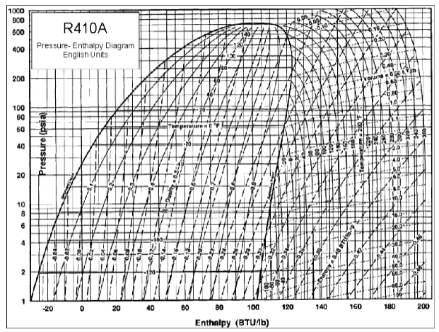
1-5. This Cogitation is to base on idea simple cycle with no losses. Figure 1-5 Refrigeration Cycle on the P-H Diagram Take the structure image of this refrigeration cycle from Figure 1-5, it becomes the P-H diagram for engineering calculation as shown in Figure 1-6. The points which are required for engineering calculation are from H 1 to H

Rankine Cycle What Is It Ideal Vs Actual Diagram Electrical4u
by S Quoilin · 2008 · Cited by 18 — Organic Rankine Cycles. By : Sylvain Quoilin ... Figure 1: PV diagram of the Carnot cycle ... The pumping cannot be seen on the Ts diagram, since in an.19 pages

A Schematic Diagram Of Supercritical Co2 Rankine Cycle With Download Scientific Diagram
Rankine Cycle T-s diagram. The stages of completing a Rankine cycle are given below:. Isentropic Compression (1 to 2): In this stage, a pump uses to transfer the water or other working medium from the water body (canal or tank etc.) into the boiler.The pump requires a small amount of energy for initial pumping. It pumps the fluid by increasing the pressure of the fluid, but fluid entropy ...

Chapter 8a Ideal Rankine And Reheat Steam Power Cycles Revised 4 25 10
P-V diagram of rankine cycle ... The Rankine cycle efficiency increased from 30.10% to 33.11% at 43bar and 32.58% to 34.66% at 61bar when the boiler temperature was increased from 350ºC to 500ºC ...

Refrigerant Ph Diagram Heat Exchangers Buffalo Brewing Blog
The Rankine cycle consists of four different components: a steam generator of some kind (for example, a boiler), a steam turbine, and condenser, and a pump. Each component changes the state and properties of the fluid that moves through it, by adding and taking away heat and work, in order to transfer energy from heat to work.

Refrigeration Cycle Diagram Explained Refrigeration Hvac R And Solar Energy Engineering
The irreversible turbine pathway (η T 1) is the dashed black line on the P-H diagram; the reversible turbine pathway is the orange dashed line. Select "Rankine cycle" to view a schematic of the cycle, and select "turbine" to show the inlet and outlet conditions for the turbine and the work generated. Download this simulation
Rankine Cycle Wolfram Demonstrations Project
Ideal Rankine Cycle (a) Schematic representation of an ideal Rankine cycle (b) T-s diagram of an ideal Rankine cycle . Application of the First law of thermodynamics to the control volume (pump, steam generator, turbine and condenser), gives . Work done on pump, per kg of water, W P = h 2-h 1 . Energy added in steam generator, q 1 = h 3-h 2
Analysis Of Constant Pressure Steam Generation Ppt Download
T-s Diagram of Lowering the Condenser Pressure : In a simple Rankine cycle, heat is added to the cycle during process 2-2'-3 (see the T-s diagram on the left). During this first stage (process 2-2'), the temperature of the water is low. That reduces the average temperature during heat addition (process 2-2'-3).
11 2 The Rankine Cycle
R134a Refrigerant Ph Chart. Enthalpy diagram of thermodynamic cycle p h diagram showing the refrigeration p h diagram thermodynamics hvac and thermodynamic scope for two phase fluid lab 3 ph diagram 1 et 102 p h. Pressure Enthalpy Chart Of Rankine Cycle With R134a For First Se Scientific Diagram.

Rankine Cycle What Is It Ideal Vs Actual Diagram Electrical4u

Refrigeration

P H Diagram Of Isopentane Application For Organic Rankine Cycle 8 Download Scientific Diagram

P H Diagram Of The Rankine Cycle With Ammonia Download Scientific Diagram

Energies Free Full Text Performance Analysis Of Cold Energy Recovery From Co2 Injection In Ship Based Carbon Capture And Storage Ccs Html
Explanation Of Rankine Cycle Me 200

Rankine Cycle Wikipedia
Theory Of Rankine Cycle Equations And Calculation
General Concepts For Development Of Thermal Instruments P

Pressure Enthalpy Chart Of Rankine Cycle With R134a For First Stage Download Scientific Diagram
Definition Of The Reheat Cycle Chegg Com

Chapter 8a Ideal Rankine And Reheat Steam Power Cycles Revised 4 25 10

Actual Rankine Cycle Versus Ideal Rankine Cycle Mechanical Engineering Concepts And Principles

Mechanical Engineering Thermodynamics Lec 19 Pt 2 Of 5 Ideal Rankine Cycle Youtube

Rankine Cycle What Is It Ideal Vs Actual Diagram Electrical4u
Rankine Cycle Processes Efficiency P V And T S Diagram

Investigate A Hybrid Open Rankine Cycle Small Scale Axial Nitrogen Expander By A Camber Line Control Point Parameterization Optimization Technique Sciencedirect
Design Of Vapor Compression Refrigeration Cycles

Definition Of An Instrument Ppt Download
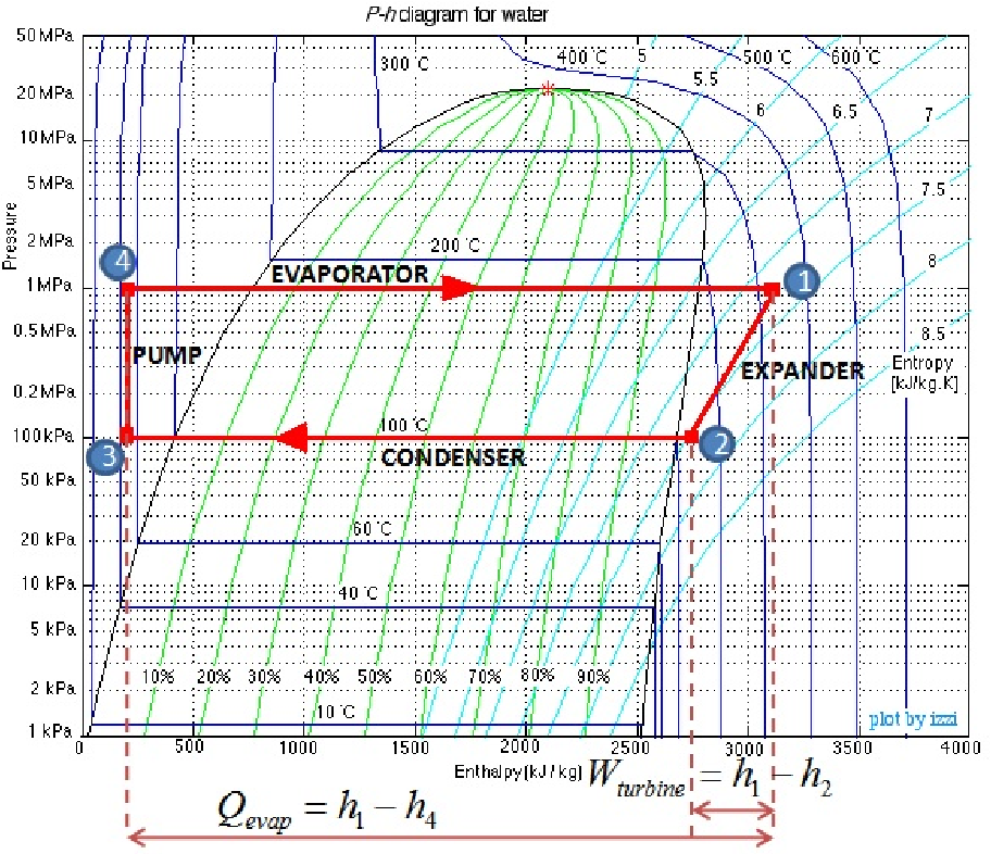
Figure 4 2 From Recuperation D Energie Par Cycle De Rankine A Bord D Un Vehicule Commande Et Gestion Energetique Semantic Scholar
Mountainscholar Org

Pressure Enthalpy Diagram For A Butane Based Subcritical Rankine Cycle Download Scientific Diagram

Rankine Cycle

Rankine Cycle An Overview Sciencedirect Topics

Pressure Enthalpy Chart Of Two Stage Rankine Cycle With R245fa Download Scientific Diagram
1

Rankine Cycle Wikipedia


Comments
Post a Comment