43 3 phase phasor diagram
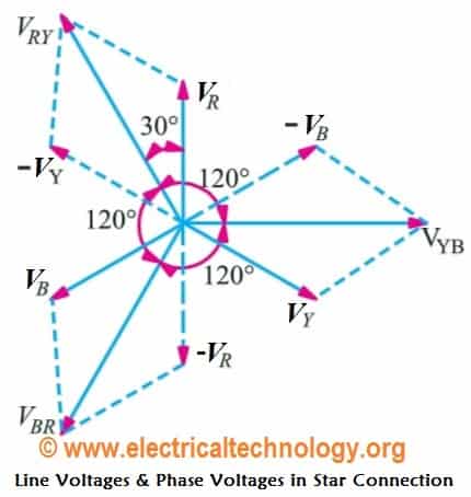
The phase voltages are all equal in magnitude but only differ in their phase angle. The three windings of the coils are connected together at points, a1, b1 and ... The phasor diagram… has a indeterminate or vague meaning ... Let's try placing phasor representations of the quantities seen from this 3 phase.33 pages
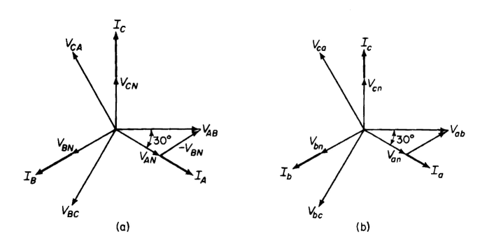
The phasor diagram of the three-phase line with equilateral spacing is shown below: Take the voltage of conductor a to neutral as a reference phasor. The potential difference between conductor a and b can be written as. Similarly, potential difference between conductors a and c is. On adding equations (1) and (2), we get. Also, Combining ...

3 phase phasor diagram
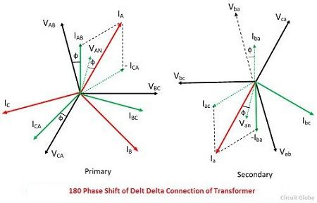
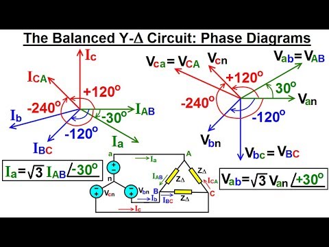
16 Sept 2021 — The most powerful tool on Fluke's three phase analyzers to make this check is the phasor diagram display. In one screen, you can quickly see ... A 3 phase fault reduces all three voltages and causes a large increase and usually highly lagging fault current symmetrically in all three phases. The angle of ...20 pages Phasor Diagram TRANSFORMER MARKINGS AND POLARITY Lesson 11_et332b.pptx 4 A B + - E AB I 2 180 degree shift C D + - Above Terminals A and D are positive at the same time + + E ... balanced 3 phase voltages and currents. Connection itself is unbalanced 2 transformers 7200 - 240/120 V Primary V p = V LL = 7200 V Secondary V LL = V p
3 phase phasor diagram. Phasor diagram of the three phase system ... Unbalance in power system caused by the addition of single phase and dynamically varying loads are unavoidable. Due ... 17-04-2020 · 3: In a purely inductive circuit or capacitive circuit, the resistance is zero. In a purely resistive circuit, the reactance is zero. 4: Due to reactance, the amplitude and phase of current will change. Due to resistance, the current and voltage remain in phase. 5: The value of reactance depends on supply frequency. 3 Phase Induction Machine: Constructional Features and Principle of Operation: Download: 30: 3 Phase Induction machine: Equivalent Circuit: ... Equivalent Circuit and Phasor Diagram: Download: 39: Synchronous Machines: OC and SC Test: Download: 40: Synchronous Machines: Power Angle Relationship, V and Inverted V Curves: 01-09-2013 · A single phase transformer has 1000 turns on its primary winding and 200 turns on its secondary winding. The transformers “no-load” current taken from the supply is …
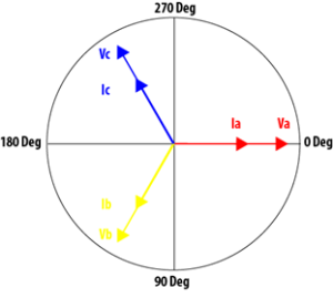
10 Jun 2020 — A three-phase system consists of three sinusoidal AC voltages and currents of identical frequency. Having 6 or more waveforms plotted on the ... Three Phase Power Review ... In a three phase power system there are three voltage phasors, separated by 120 electrical degrees. ... Up to this point the three ... voltage and phase measurement (relative to the appropriate reference), you can measure a phasor value. With a two channel oscilloscope, you have the ability to trigger on each waveform and electronically switch (chop or alt) between them as well. A block diagram of a oscilloscope has now become as shown in figure 10. Construct phasor diagrams of three-phase sources and loads. Identify the time and phasor plots of a three phase set of voltages and currents.
Phasor Diagram TRANSFORMER MARKINGS AND POLARITY Lesson 11_et332b.pptx 4 A B + - E AB I 2 180 degree shift C D + - Above Terminals A and D are positive at the same time + + E ... balanced 3 phase voltages and currents. Connection itself is unbalanced 2 transformers 7200 - 240/120 V Primary V p = V LL = 7200 V Secondary V LL = V p A 3 phase fault reduces all three voltages and causes a large increase and usually highly lagging fault current symmetrically in all three phases. The angle of ...20 pages 16 Sept 2021 — The most powerful tool on Fluke's three phase analyzers to make this check is the phasor diagram display. In one screen, you can quickly see ...
3 Phase Ac Calculations Revisited Dataforth

Phasor Diagram And Phasor Algebra Used In Ac Circuits

Analysis Of Simple Three Phase Circuits Four Wire Systems Three Wire Balanced Systems Electric Power Systems
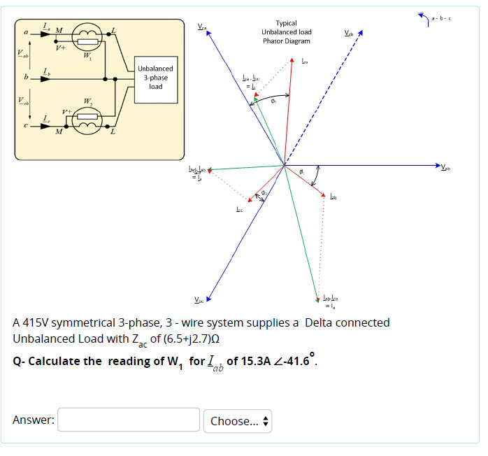
Solved A B T Typical Unbalanced Load Phasor Diagram Chegg Com

Three Phase Ac Power Calculator Balanced Load Electrical Rf And Electronics Calculators Online Unit Converters
Three Phase Delta Connection Three Phase Power Voltage Current Electrical Academia
Phasor Diagrams And Phasor Algebra Electronics Lab Com

A Three Phase Phasor Diagram B Symmetrical Six Phase Phasor Download Scientific Diagram
Electrical Power Explained Part 3 Balanced Three Phase Ac Power Fluke
Three Phase Transformer Connections Circuit Globe
Phasor Wikipedia
Induction Motor Phasor Diagram Electrical Concepts

Power In A Star Connection Three Phase Power Electrical Simple
Ent 2493 Electrical Circuit And Machine 3 Phase
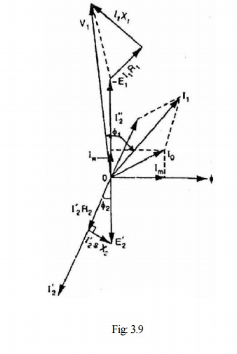
Phasor Diagram Of Three Phase Induction Motor

Review Of Three Phase Systems
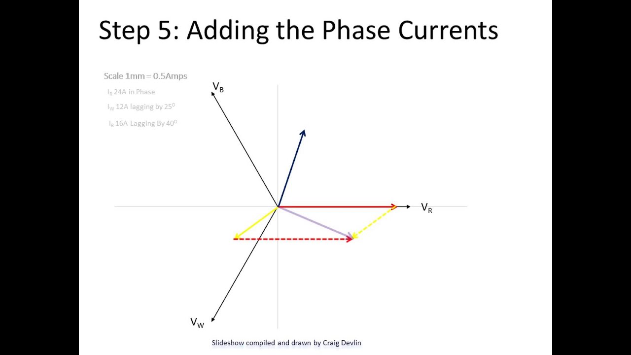
Resolving Neutral Current In A 3 Phase Circuit Updated Http Youtu Be Kghtgs2n2ue Youtube
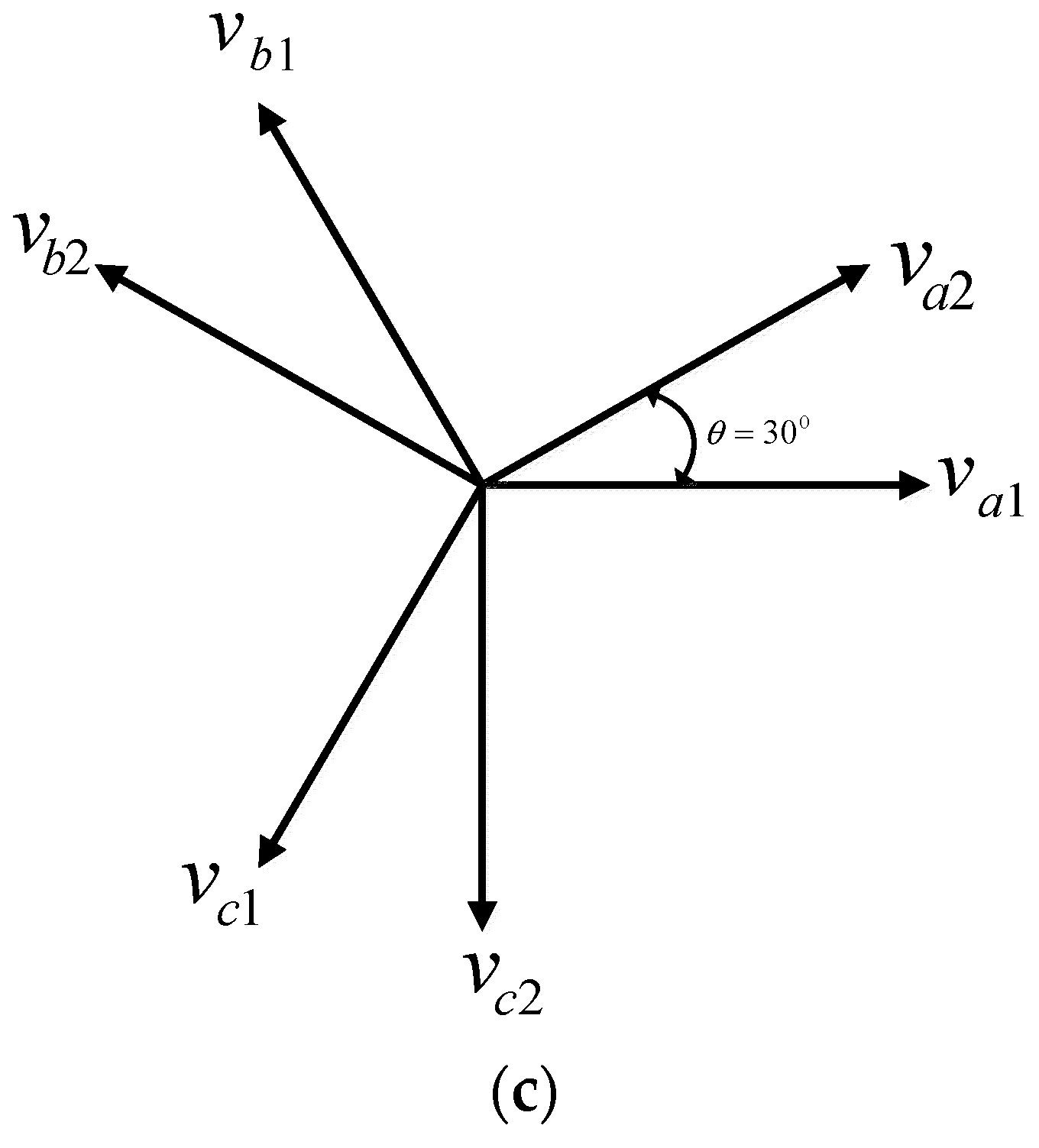
Electronics Free Full Text Systematic Implementation Of Multi Phase Power Supply Three To Six Conversion System Html

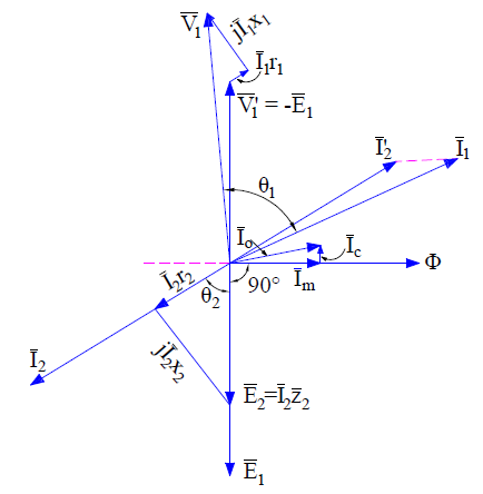
Vector Diagram Of Transformer What It Is How To Draw Electrical4u
Electrical Engineering Ch 13 3 Phase Circuit 20 Of 42 What Is The Phase Diagram Of A Y Delta Youtube
Vector Diagrams Powermetrix Electric Meter Testing Equipment
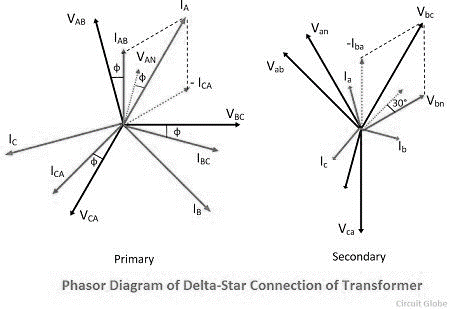
Three Phase Transformer Javatpoint

An Introduction To Using Phasor Diagrams On Oscilloscopes For 3 Phase Power Analysis Tektronix

Learn Openenergymonitor
Three Phase Networks

Three Phase Star Connection Y Three Phase Power Voltage Current Electrical Academia
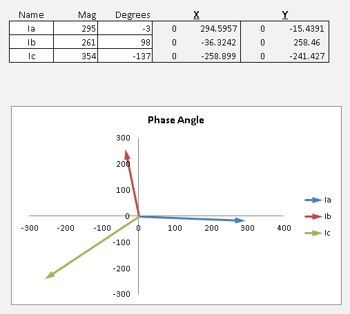
Excel Phasor Diagram Builder

Phasor Diagram Of Induction Motor Ac Machines Electrical Machines Youtube
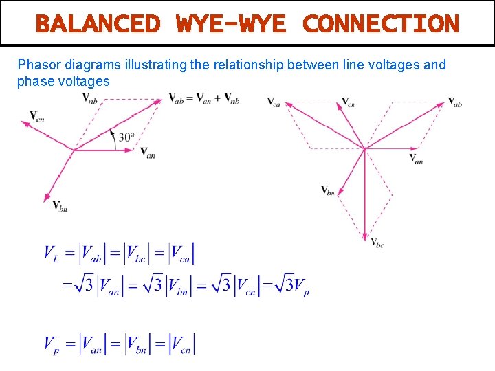
Wye Wye Connection

3 Three Phase Voltages Shown In A Phasor Diagram Download Scientific Diagram
Na Eventscloud Com
Na Eventscloud Com

Three Phase Electric Power Wikipedia
Star Connection Y 3 Phase Power Voltage Current Values

Phasor Diagram Of A Synchronous Generator The Engineering Knowledge

Phasor Diagram Of Induction Motor
How To Draw Phasor Diagrams For Various Circuits Explain In Detail Quora

Measurement Of 3 Phase Power Using 2 Cts And 1 Wattmeter

3 Phase Ac Calculations Revisited Dataforth
1
Three Phase Networks
Excel Phasor Diagram Builder

Phasor Diagram Showing The Balanced Three Phase Fluxses A B C And The Download Scientific Diagram


Comments
Post a Comment