38 fe3c phase diagram
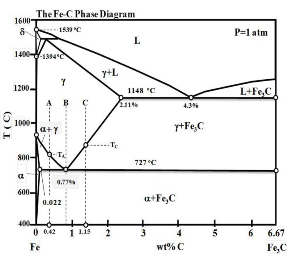
Refer to the Fe-Fe3C phase diagram in your Pre-Exam Material Handout. An alloy containing 1.15 wt% C is slowly cooled from the austenite region to just below the eutectoid temperature. At this temperature, the steel will be comprised of: O a. 96 wt% pearlite, 4 wt% proeutectoid cementite, 12 wt% Fe3C and 88 wt% ferrite O b. 93 wt% pearlite, 7 wt% Download scientific diagram | Fe-Fe3C Phase Diagram with approximate carbon levels of HSLA (green), DP (pink) and TRIP (blue) [9]. from publication: Resistance Spot Welding of Advanced High ...
phase diagram. The nonequilibrium conditions that are usually encountered inpractice, however, necessitate the knowledge of a much greater por- tion of the diagram. Therefore, a thorough under- standing of alloy phase diagrams in general and their practical use will prove to be of great help to a metallurgist expected to solve problems in any of the areas mentioned above. …

Fe3c phase diagram
It forms a solid solution with alpha (alpha ferrite), gamma (austenite), and delta (delta ferrite) phases of iron. These are important phases in Fe - Fe3C phase diagram. Between the single-phase fields, there are found regions with mixtures of two phases, such as ferrite and cementite, austenite and cementite, and ferrite and austenite. Fe Fe3C Phase change diagram. It is an iron carbon alloy where most of the carbon is present as meta‐stable iron carbide called cementite. The upper limit of carbon content is 2%. Phase diagram helps us guess the structure of alloys and their properties. Let us look at what kinds of structure steel could have depending on its composition. Cementite, a metastable phase of this alloy with a fixed composition of Fe3C, is a metastable phase of this alloy. At room temperature, it decomposes extremely slowly into iron and carbon (graphite). This decomposition time is long, and it will take much longer than the application's service life at room temperature.
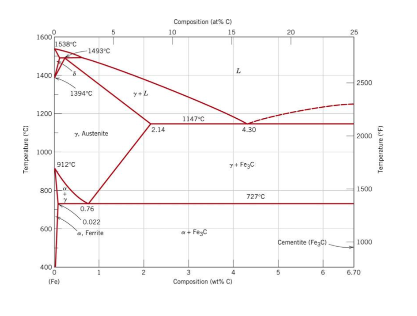
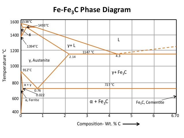
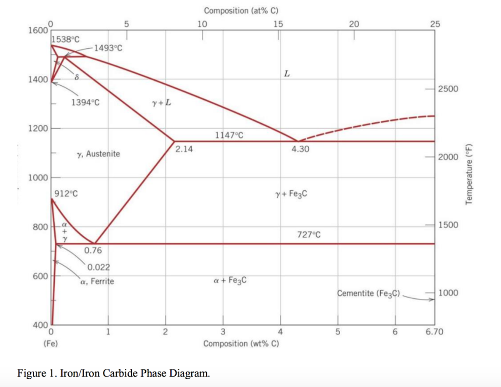
Fe3c phase diagram. Fig 1: Fe-Fe3C Phase Diagram (clickable), Materials Science and Metallurgy, 4th ed., Pollack, Prentice-Hall, 1988 Figure 1 shows the equilibrium diagram for combinations of carbon in a solid solution of iron. The diagram shows iron and carbons combined to form Fe-Fe3C at the 6.67%C end of the diagram. IRON-CARBON (Fe-C) PHASE DIAGRAM (EXAMPLE 1) 2 important points - Eutectoid (B) g a+Fe 3 C - Eutectic (A) L g+Fe 3 C Fe 3 e) 1600 1400 1200 1000 800 600 400 0 1 2 3 4 5 6 6.7 L g (austenite) g+L g+Fe 3 C a+Fe 3 C d (Fe)C, wt% C 1148ºC T(ºC) a727ºC = Teutectoid 4.30 Result: Pearlite = alternating layers of aand Fe 3 C phases 120 mm0.76 B g g g In the figure, there is the iron–iron carbide (Fe–Fe3C) phase diagram. The percentage of carbon present and the temperature define the phase of the iron carbon alloy and therefore its physical characteristics and mechanical properties. The percentage of carbon determines the type of the ferrous alloy: iron, steel or cast iron. Source: wikipedia.org Läpple, Volker – Wärmebehandlung … This video answers the most frequently asked questions students have about iron- iron carbide phase diagram microstructures. If you have any questions or com...
Binary phase diagram If a system consists of two components, equilibrium of phases exist is depicted by binary phase diagram. For most systems, pressure is constant, thus independently variable parameters are –temperature and composition. Two components can be either two metals (Cu and Ni), or a metal and a compound (Fe and Fe3C), or two ... At the carbon-rich side of the metastable Fe-C phase diagram we find cementite (Fe3C). Of less interest, except for highly alloyed steels, is the delta-ferrite at the highest temperatures. Phase diagrams; Equilibria in gases; Some example exercises include: Define the system Co. What phase is most stable at 1 bar and 1000K? Evaluate the molar Gibbs energy of the compound Fe3C at 1000 °C. Calculate the ternary phase diagram W-Co-C at 1 bar and 1400 °C. Perform the calculation by varying the mole percent of Co and C. The Iron Carbide (Fe Fe3C) Phase Diagram The Iron ‐Iron Carbide (Fe‐Fe 3 C) Phase Diagram PeritecticL+ δ = γ at T=1493oC and 0.18wt%C Eutectic L = γ +Fe 3 C at T=1147oC and 4.3wt%C Eutectoid γ = α +Fe 3 C at T=727oC and 0.77wt%C Phases Present L Reactions
What is an Iron Carbon phase diagram ? Hello everyone. Iron carbon phase diagram In their simplest form, steels are alloys of Iron (Fe) and Carbon (C). The study of the constitution and structure of iron and steel start with the iron-carbon phase diagram. It is also the basis understanding of the heat treatment of steels. In the figure, there is the iron–iron carbide (Fe–Fe3C) phase diagram. The percentage of carbon present and the temperature define the phase of the iron carbon alloy and therefore its physical characteristics and mechanical properties. The percentage of carbon determines the type of the ferrous alloy: iron, steel or cast iron. Source: wikipedia.org Läpple, Volker – Wärmebehandlung … Review Fe-C phase diagram The influence of other alloying elements REutectoid changes. 6 Summary. 1000 700 ("t % C) ite 1000 700 500 400 72700. Fe3C 2.0 1.0 Composition (wt% C) a 0.022 C'o U Fe3C a + Fegc 6.70 Composition (wt% C) 0.76 . 0.8 0.6 0.4 0 0.2 10 12 Concentration of alloying elements (wt%) 1200 This sceencast is part four of our series about phase diagrams. This sceencast is focused on addressing issues students have with Iron-Iron Carbide (Steel) E...
34 Fe Fe3c Phase Diagram - Free Wiring Diagram Source
A mixed-phase of (γFe + Fe3C) existing from 4.3% to 6.67% between 723 Degree Centigrade to 1145 Degree Centigrade is known as Ledeburate Phase. Why Cast Iron(C.I) is not Heat Treatable? Maximum percentage of carbon that steel can be produced is 1.5 % only.
![[열처리]ì² -탄소 í‰í˜•ìƒíƒœë„(Fe-Fe3C ìƒíƒœë„)](https://mechaniclove.com/wp-content/uploads/2017/12/phase_diagram_large.gif)
[열처리]ì² -탄소 í‰í˜•ìƒíƒœë„(Fe-Fe3C ìƒíƒœë„)
Fe-Fe3C phase diagram The phase diagram is made up of a number of phase boundaries. As was have seen in the last part of Tutorial 7 , these boundaries can be found by finding a point on the boundary, then tracing the boundary as a function of element content.
Diagrama unifilar sub - estacion de 800 kva (74.19 KB ...
In the figure, there is the iron-iron carbide (Fe-Fe3C) phase diagram. The percentage of carbon present and the temperature define the phase of the iron carbon alloy and therefore its physical characteristics and mechanical properties. The percentage of carbon determines the type of the ferrous alloy: iron, steel or cast iron.

3d Human Male Xray Digestive System Stock Photo - Download ...
In the present evaluation, the assessed stable Fe-C (graphite) and metastable Fe-Fe3C (cementite) equilibrium phase diagrams for 0 to 25 at.% C are based on thermodynamic calculations reported by [79Schl] and [84Oht].

80 Amp 30mA RCD 2 Pole - Hager
In presented paper the algorithm for Fe-Fe3C phase diagram calculation and developed computer program, PD_Fe_Fe3C are presented. Results of calculations using this program were compared with date ...
Solved: A) The Fe-Fe3C Phase Diagram (assume Very Slow Coo ...
06.03.2016 · Fig 2 Iron- carbon phase diagram. Steels that are 100 % austenite must have temperature-composition coordinates within the area of austenite shown in the phase diagram at Fig 2. Steels that are ferrite must have temperature-composition coordinates in the narrow region at the lower left of the Fe-C phase diagram. The maximum amount of C which dissolves into …

Fe Fe3c Phase Diagram
Cementiteor iron carbide is very hard, brittle intermetallic compound of iron & carbon, as Fe3C, contains 6.67 % C. It is the hardest structure that appears on the diagram, exact melting point unknown. Its crystal structure is orthorhombic. It is has low tensile strength (approx. 5,000 psi), but high compressive strength.

Fe Fe3c Phase Diagram - Free Wiring Diagram
The Iron ‐ Iron Carbide (Fe‐Fe3C) Phase Diagram Reactions Phases Present Peritectic L + δ = γ Lat T=1493oC and 0.18wt%C δ ferrite delta Eutectic L = γ + Fe3C Bcc structure at T=1147oC and 4.3wt%C Paramagnetic Eutectoid γ = α + Fe3C γ austeniteat T=727oC and 0.77wt%C Fcc structure Non‐magnetic ductileMax. solubility of C α ferrite Fe3C cementitein ferrite=0.022% Bcc structure ...

Fe Fe3c Phase Diagram - General Wiring Diagram
ADVERTISEMENTS: The Iron-Iron carbide (Fe-Fe3C) is defined by five individual phases and four invariant reactions. Five phases are- α-ferrite (BCC) Fe-C solid solution, γ-austenite (FCC) Fe-C solid solution, δ -ferrite (BCC) Fe-C solid solution, Fe3C (iron carbide) or cementite - an inter- metallic compound and liquid Fe-C solution. Four invariant reactions are eutectoid, eutectic ...

pktrucks HIAB cranes instruction movie - using the load ...
Phase Diagram of Steel Fe-Fe3C Phase Diagram, Materials Science... Phase Diagrams Fe-Mn, Fe-Co, Fe-Mo In pure iron, the A4 (1394 °C) and... Random Posts. Phase Diagram of Steel The diagram shows iron and carbons combined to form Fe-Fe3C at the 6.67%C end of the diagram. The left side of the diagr... Inclusions Phenomena at Steelmaking One tonne of steel, a cube …

Fe-fe3c Diagram Verygood | Alloy | Heat Treating
12.02.2016 · IRON-CARBON EQUILIBRIUM DIAGRAM Fig. shows, the Fe-C equilibrium diagram in which various structure (obtained during heating and cooling), phases and IRON-CARBON EQUILIBRIUM DIAGRAM
Fe Fe3c Phase Diagram - Wiring Site Resource
Check Pages 1 - 7 of The iron-iron carbide (Fe-Fe3C) phase diagram in the flip PDF version. The iron-iron carbide (Fe-Fe3C) phase diagram was published by on 2015-05-11. Find more similar flip PDFs like The iron-iron carbide (Fe-Fe3C) phase diagram. Download The iron-iron carbide (Fe-Fe3C) phase diagram PDF for free.

Fe Fe3c Phase Diagram - Diagram For You
Iron-Carbon (Fe-C) Phase Diagram 1. Eutectic (A): L T (°C) 1600 Adapted from Fig. 10.28, Callister & Rethwisch 3e. L 1400 + Fe3C 2.

Ray Diagrams: Concave and Convex Lenses and Mirrors ...
mp-510623: Fe3C (orthorhombic, Pnma, 62) Edit Crystal. Generate Phase Diagram. Compositional Phase Diagram. Aqueous Stability (Pourbaix) Tags: Cohenite Iron carbide (3/1) Cementite Iron carbide High pressure experimental phase Iron carbide (3/1) - theta. CIF VASP POSCAR CSSR JSON.
Electric Transformer - 440-227v DWG Block for AutoCAD ...
Feb 11, 2016 · เหล็กหล่อ เป็นเหล็กที่มีปริมาณคาร์บอนมากกว่า 2 % ด้วยคุณสมบัติเฉพาะตัวของเหล็กหล่อหลายประการ จึงนิยมใช้งานกันอย่างแพร่หลาย
Large Mollier Chart (Foot-Pound-Fahrenheit Units ...
Martensite is not shown in the equilibrium phase diagram of the iron-carbon system because it is not an equilibrium phase. Equilibrium phases form by slow cooling rates allowing sufficient time for diffusion, whereas martensite is usually formed by fast cooling rates. Since chemical processes (the attainment of equilibrium) accelerate at higher temperature, martensite is easily …

FE-Fe3C phase diagram | Powerpoint design templates ...
Giản đồ pha (phase diagram): Một cách tổng quát, trong KHVL, giản đồ pha được hiểu là một loại đồ thị biểu diễn các điều kiện cân bằng giữa các pha riêng biệt (các pha có thể phân biệt về mặt nhiệt động).
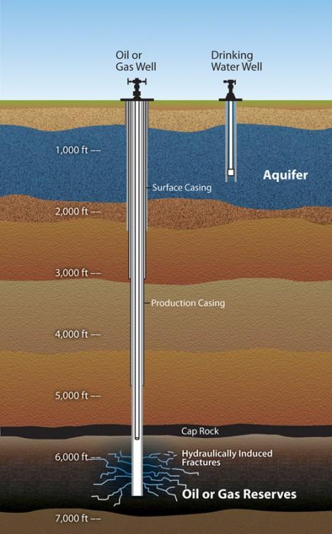
Fracking - Water Education Foundation
The figure above shows a typical Fe-Fe3C phase diagram. Case 1: For composition range between 0.022 and 0.76 (Hypo-eutectoid steel) When we come down from a temperature of 1000 degrees to say 600 degrees, the order of phases are γ ,Austenite ------ ( α ,Ferrite + γ )------- ( α + F e 3 C), Pearlite.

Power Inverter with TL494 and H Bridge Power MOSFETs ...
The boundaries, intersecting each other, mark certain regions on the Fe3C diagram. Within each region, a different phase or two phases may exist together. At the boundary, the phase change occurs. These regions are the phase fields. They indicate the phases present for a certain composition and temperature of the alloy.
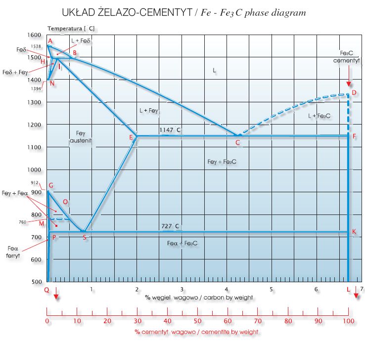
Układ żelazo - cementyt / Fe - Fe3C phase diagram ...
• Phase diagrams are useful tools to determine:--the number and types of phases,--the wt% of each phase,--and the composition of each phase for a given T and composition of the system. • Alloying to produce a solid solution usually--increases the tensile strength (TS)--decreases the ductility. • Binary eutectics and binary eutectoids ...
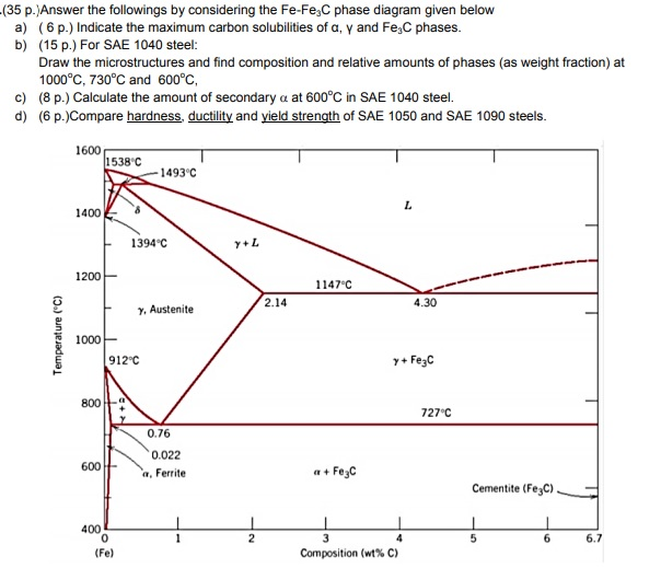
Solved: Answer The Followings By Considering The Fe-Fe3C P ...
Iron carbide (Fe 3 C) is often labeled as the uncorroded portion of the steel. It is primarily associated with mild steels having a high carbon content and a ferritic-pearlitic microstructure. During corrosion of such steel, the ferrite phase dissolves and a porous iron carbide network is exposed (see Fig. 7.6).Given that iron carbide is an electronic conductor, this porous network serves as ...
What is Pearlite - Definition | Material Properties
Iron-Cementite diagram is not a true equilibrium diagram, since equilibrium means no change of phase with time, however long it may be. Graphite is more stable form of carbon. Cementite is a metastable phase, which decomposes to graphite if given long periods of time. Graphitisation, however, rarely occurs in steels and may take years to form. Thus, cementite, though a …

Wiring my Reversable switch problem
Fe-Fe 3 C T-T-T Diagram, Adapted from Callister pg. 295, Fig. 10.6 The time-temperature transformation curves correspond to the start and finish of transformations which extend into the range of temperatures where austenite transforms to pearlite. Above 550 C, austenite transforms completely to pearlite.
A Diagram of the Layers of the Skin | ClipArt ETC
Cementite, a metastable phase of this alloy with a fixed composition of Fe3C, is a metastable phase of this alloy. At room temperature, it decomposes extremely slowly into iron and carbon (graphite). This decomposition time is long, and it will take much longer than the application's service life at room temperature.

Convert 3 phase air compressor to single phase_Powerex ...
Fe Fe3C Phase change diagram. It is an iron carbon alloy where most of the carbon is present as meta‐stable iron carbide called cementite. The upper limit of carbon content is 2%. Phase diagram helps us guess the structure of alloys and their properties. Let us look at what kinds of structure steel could have depending on its composition.

Rewiring transformer from 3 phase to single phase
It forms a solid solution with alpha (alpha ferrite), gamma (austenite), and delta (delta ferrite) phases of iron. These are important phases in Fe - Fe3C phase diagram. Between the single-phase fields, there are found regions with mixtures of two phases, such as ferrite and cementite, austenite and cementite, and ferrite and austenite.

Fe3C Phase Diagram

Fe Fe3c Phase Diagram - Drivenheisenberg
Fe-Fe3C phase diagram of common S235JR construction steel ...
Solved: Question 2: Use The Fe-C Phase Diagram In Fig. 1 ...
Solved: A) Identify All Phases Marked On The Phase Diagram ...
Curved Diagram of Semi-Circle PPT - SlideModel
NASA experiments will watch eclipse's effect on atmosphere ...

Matrix Diagram (Y-Shaped) | Data Viz Project

Phase diagram of Pb-Sn alloys with sketches of the ...
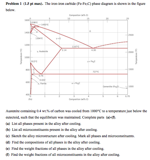
Solved: The Iron-iron Carbide (Fe-Fe3C) Phase Diagram Is S ...

mekanika pikiran: fe-fe3c diagram
![iron-carbon_diagram.png [SubsTech]](http://www.substech.com/dokuwiki/lib/exe/fetch.php?cache=cache&w=678&h=542&media=iron-carbon_diagram.png)
iron-carbon_diagram.png [SubsTech]


Comments
Post a Comment