38 ph diagram for refrigeration cycle
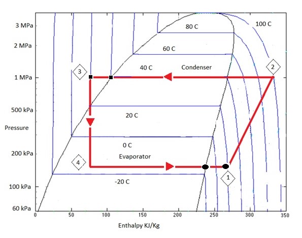
Figure 1-5 Refrigeration Cycle on the P-H Diagram Take the structure image of this refrigeration cycle from Figure 1-5, it becomes the P-H diagram for engineering calculation as shown in Figure 1-6. The points which are required for engineering calculation are from H 1 to H 6 as shown in the Figure 1-6. H 1 to H 2 is the adiabatic compression of the compressor for the … 20 Mar 2018 — When you can draw a refrigeration cycle on a p-h diagram, you can easily obtain the refrigerant characteristics through the diagram.
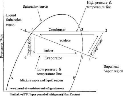
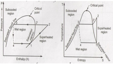
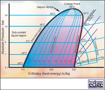
Understanding the basic refrigeration cycle diagram also helps us to find subcooled, superheat and to troubleshoot refrigeration processes much easier. Finding subcooled and superheat is beyond the scope of this discussion. As you can see in the Ph diagram below. Saturation curve this curve represents what state (vapor or liquid) and region (sub-cooled, latent heat, and …

Ph diagram for refrigeration cycle
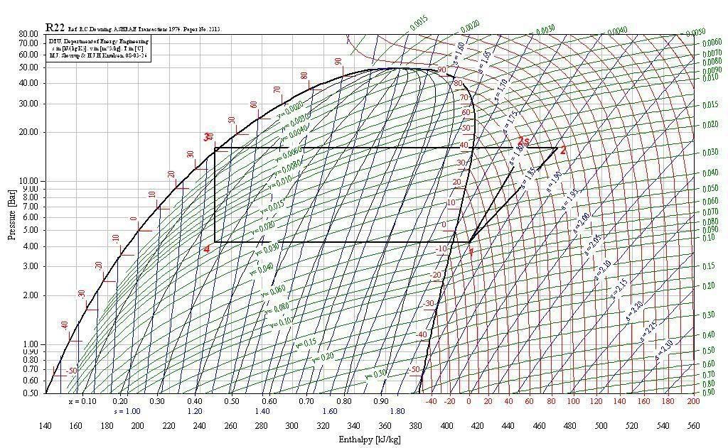
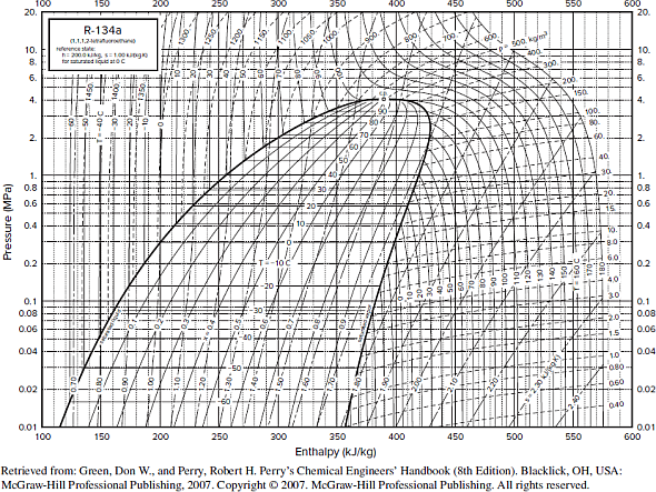
The following sections will show each specific part of the refrigeration cycle on the pressure-enthalpy diagram and it will also highlight the important points and calculations needed. Throughout this explanation the refrigerant R-134a is used as an example. It is recommended that the engineer get a copy of the P-H diagram for R-134a and the ... The vapor compression refrigeration cycle consists of four processes: (1-2) compressing refrigerant in compressor isentropically, (2-3) condensation at constant ... R22 P/H Diagram * Diagram created using REFPROP – NIST Reference Fluid Properties As can be seen, the critical point of R-22 is more than 200°F, placing it well above the operating conditions of typical refrigeration systems. This can be contrasted with the CO 2 PH diagram, with a critical point of 88°F. This temperature is often exceeded ...
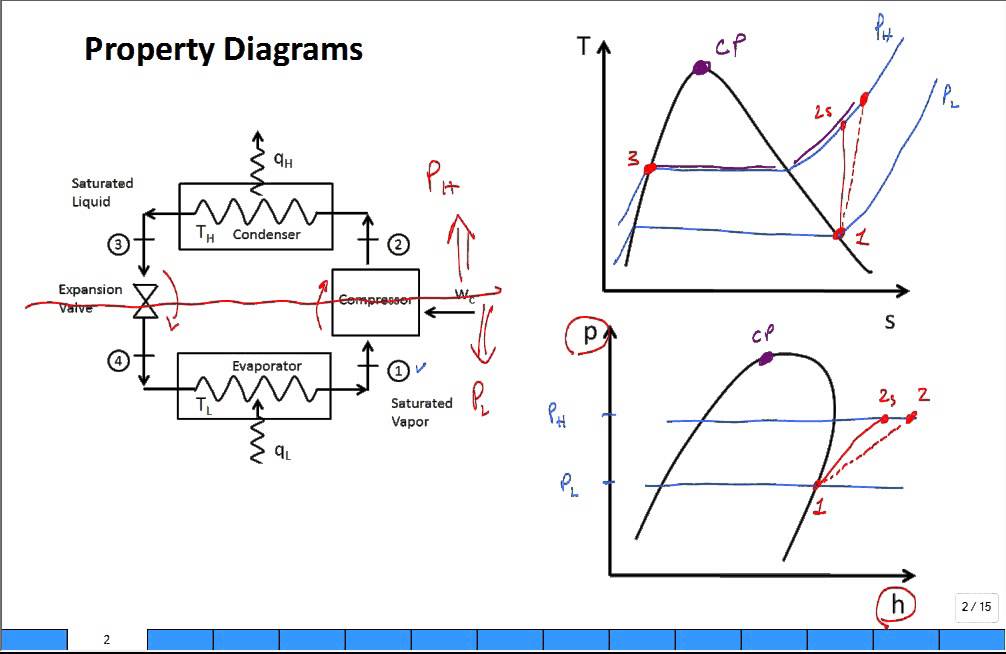
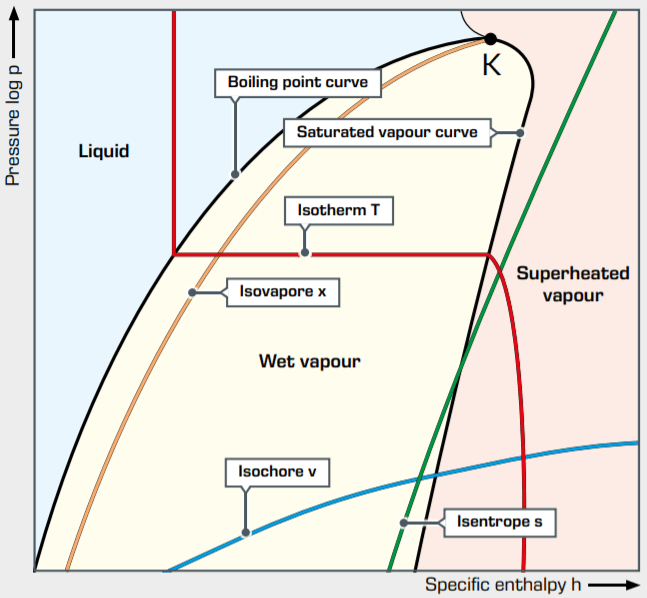
Ph diagram for refrigeration cycle. Refrigeration handbook 1. Basic heat transfer 2. Compression cycle 2.1 The pressure-enthalpy diagram; 2.2 Basic components; 2.3 The basic cycle in a log Ph diagram; 2.4 The complex cycle in a log Ph diagram; 2.5 Other components; 3. Compressors 4. Expansion valves 5. Refrigerants 6. Evaporators 7. Condensers 8. Practical advice The log p-h diagram shows the thermodynamic state vari- ables in the respective phase. • pressure p. • specific enthalpy h. • temperature T. • specific volume v.2 pages Understanding the basic refrigeration cycle diagram also helps us to find subcooled, superheat and to troubleshoot refrigeration processes much easier. As we can see in the Ph diagram below. Saturation curve this curve represents what state (vapor or liquid) and region (sub-cooled, latent heat, and superheat) the refrigerant is in. It also splits into two sections a saturation liquid … Figure 2-4: Wet refrigeration Cycle - The expander has been substituted by a throttling valve. If an expander had been used the line from d to a would be a vertical line. This is also done for mechanical reasons. The refrigeration cycles can also be represented in a P-H diagram. Figure 2-5: P-H diagram representation of a dry refrigeration cycle
Reversed Carnot Cycle s T T C T H. 4 0.0 5.0 10.0 15.0 20.0 25.0 30.0-40.0 -35.0 -30.0 -25.0 -20.0 -15.0 -10.0 -5.0 0.0 5.0 10.0 Cold-Side Temperature - T C, C COP c 20.0 30.0 40.0 50.0 60.0 70.0 Carnot Cycle Performance Sat Cond T, °C Reversed Carnot Vapor Compression Cycle s T T C T H. 5 Reversed Rankine Vapor Compression Cycle s T T C T H Superheat Horn … Air-Conditioning and Refrigeration. Mechanical Engineering Handbook. Pawan Gupta. Download PDF. Download Full PDF Package. This paper. A short summary of this paper. 22 Full PDFs related to this paper. READ PAPER. Air-Conditioning and Refrigeration. Mechanical Engineering Handbook. Download. Air-Conditioning and Refrigeration. Mechanical … The Rankine cycle is an idealized thermodynamic cycle describing the process by which certain heat engines, such as steam turbines or reciprocating steam engines, allow mechanical work to be extracted from a fluid as it moves between a heat source and heat sink. The Rankine cycle is named after William John Macquorn Rankine, a Scottish polymath professor at Glasgow … Log p-h diagram — In general, a log p-h diagram shows the aggregate state of a substance, depending on pressure and heat. For refrigeration, the diagram is ...
R22 P/H Diagram * Diagram created using REFPROP – NIST Reference Fluid Properties As can be seen, the critical point of R-22 is more than 200°F, placing it well above the operating conditions of typical refrigeration systems. This can be contrasted with the CO 2 PH diagram, with a critical point of 88°F. This temperature is often exceeded ... The vapor compression refrigeration cycle consists of four processes: (1-2) compressing refrigerant in compressor isentropically, (2-3) condensation at constant ... The following sections will show each specific part of the refrigeration cycle on the pressure-enthalpy diagram and it will also highlight the important points and calculations needed. Throughout this explanation the refrigerant R-134a is used as an example. It is recommended that the engineer get a copy of the P-H diagram for R-134a and the ...
Refrigeration: Refrigeration Cycle With Freon 22
Basic Refrigeration Cycle

Ph Diagram For Refrigeration Cycle - Hanenhuusholli

Refrigeration: Ph Diagram Refrigeration Cycle

iphone, ios, home screen, close up, pixels, retina, smartphone, icon, ios 14, icon, screen, phone, sleep cycle, alarm clock

Efficiency - Measuring Refrigeration

Ph Diagram For Refrigeration Cycle - General Wiring Diagram
Ph Diagram For Refrigeration Cycle - Drivenheisenberg

e P-h diagram of refrigeration cycles with suction gas ...

Refrigeration: Refrigeration Ph Chart
Ph Diagram For Refrigeration Cycle - Diagram Resource Gallery

Refrigeration: Refrigeration Ph Chart
Refrigeration: Refrigeration Ph Chart

Natracare organic cotton tampons
Property diagrams TS and PH for refrigeration 2 - YouTube

Closeup of skeleton foot model

Refrigeration: Ph Diagram Refrigeration Cycle

Schematic and P-h diagram of the conventional cascade ...

vapour compression refrigeration cycle on p-h diagram ...

CO2 as a Refrigerant — Introduction to Transcritical ...

The cycle of vapor compression heat pump in the ph-diagram ...
Ph Diagram For Refrigeration Cycle - General Wiring Diagram

Ideal refrigeration cycle P-h diagram; 1→2: isobaric ...

That’s life

Refrigeration: Refrigeration Ph Cycle

Schematic diagram of an ejector refrigeration cycle and ...

Explain vapour compression refrigeration cycle on T-S and ...

P-h diagram of ½ cycle refrigeration on LPG fueled vehicle ...
Refrigeration cycle diagram explained - Refrigeration ...

Efficiency - Measuring Refrigeration
Refrigeration: Ph Chart Refrigeration Cycle

R134a Refrigerant Ph Chart - Best Picture Of Chart ...
Solved: A vapor-compression refrigeration system operates ...
Refrigeration: P H Graph Refrigeration

The Refrigeration Cycle

Vapor-Compression Refrigeration Cycle (Interactive ...

JSRAE, Japanese Society for Refrigerating and ...

Ph Diagram For Refrigeration Cycle - Ekerekizul


Comments
Post a Comment