38 pneumatic circuit diagram
Circuits: 5,228 32 by Lucas Reed in Electronics by BrownDogGadgets in LEDs by AutoRob in Arduino by Electroninks in Electronics by Paulbacca in Electronics by Bare Conductive in Art by amandaghassaei in Electronics by steveastrouk in Solder... PneuDraw allows you to draw pneumatic circuits quickly and easily. ... symbols as well as special symbols to design business processes and flow diagrams.
Like the title says I am looking for a program to create a circuit diagram for a switch cabinet that controls a motor and brake and some other things. I am currently using SOLIDWORkS electrical but don't like it. I would appreciate any suggestions of programs that you have used in the past and have found pleasant to use. Thanks in advance.
Pneumatic circuit diagram
My wife purchased a tanning bed and I am trying to wire it up however it will not turn on. I am guessing it is because there is no timer to tell the unit to power on. Attached is the image of the timer circuit can someone please explain what the "Start Remote" section means? From what I can tell it seems to be a ground cable that goes on and off. ​ https://preview.redd.it/aocziemmvae81.png?width=384&format=png&auto=webp&s=058ab5336234b94e52cdb82c3c4392d132c13652 Here are a number of highest rated Pneumatic Schematic Valve Symbols pictures upon internet. We identified it from obedient source. Its submitted by paperwork in the best field. We believe this kind of Pneumatic Schematic Valve Symbols graphic could possibly be the most trending topic subsequently we portion it in google plus or facebook. I've been using a flowchart drawing tool to make circuit diagrams, and I'm sure there must be a better way. ​ What do you use to draw circuits?
Pneumatic circuit diagram. Pneumatic circuit diagrams and parts lists can also be quickly created on a PC. These are arranged into groups according to drives, valves, valve terminals, compressed air preparation, vacuum technology, flow control and non-return valves, etc. For school I have to do a project which I need a circuit diagram of a motherboard for. My motherboard is an MSI Tomahawk B450 Max, but any motherboard circuit diagram will do if you have one. Thanks! Help pls Series circuits work on both hydraulic and pneumatic actuators. Pneumatic Systems - Control Systems Questions and Answers Jul 24, 2019 · A resistor is an electrical component that regulates or restricts the flow of an electrical current in a circuit. This can also be used to provide a specific voltage to a transistor.
Fluiddraw is an indispensable design software for electrical and pneumatic circuit diagrams that makes it easier to plan complete systems as well as implement individual components. For more than 20 years, fluidsim® has been the world's leading circuit diagram design and simulation program for pneumat Read Free Festo Electro Pneumatic Circuit Diagram Cagavs. Read Free Festo Electro Pneumatic Circuit Diagram Cagavs. Festo Electro Pneumatic Circuit Diagram Cagavs ... Identify the symbols for pneumatic components from either ANSI or ISO drawings. Draw a complete schematic based on given parameters using drawing software. Apply the given parameters to the drawn components and simulate circuit operation. Connect the complete circuit on a hydraulic trainer and verify proper operation. 19 Watts Simple Amplifier Schematic Circuit Diagram. Power Amplifier Circuit - 25 Watts Schematic Circuit Diagram. Mini Audio Amplifier Schematic Circuit Diagram. Hi Fi Amplifier Circuit - 2X12 Watts Schematic Circuit Diagram. Low Cost 150 Watt Amplifier Schematic Circuit Diagram. Remote Circuit Diagrams. 5 Channel IR Remote Control System ...
Hydraulic circuits | Mechanical How Does Elevator Works, Circuit Diagram & Types of ElevatorsSpecalog for 315C/315C L Hydraulic Excavator, AEHQ5543Hydraulic brake - WikipediaAutomation Studio™ - Hydraulic, Pneumatic, Electrical and PC650LC-11 In pneumatic circuit diagrams, the components are arranged the way that the flow of energy always flows from the bottom up (as opposed to electrical ... A Regulator in a Circuit Pneumatic Circuits A regulator has two major functions. One is to pass air at constant secondary pressure, regard-less of the flow variation or upstream pressure and the other is to reduce the pressure to a level that meets with work requirements, minimizing the amount of wasted pressurized air. Let's take a I found this video online [https://www.youtube.com/watch?v=v90yD\_W9kbY](https://www.youtube.com/watch?v=v90yD_W9kbY) And I need to recreate this circuit to run a pneumatic hand engraver. (can be seen here [https://www.youtube.com/watch?v=GdT7hMV\_cfo](https://www.youtube.com/watch?v=GdT7hMV_cfo)) I am trying to create a oscillating circuit that I can plug into an air-brush compress to run a hand held pneumatic engraver. It uses the positive and negative pressure of a modified compressor wit...
Solved Q1) Design an electro-pneumatic circuit to implement ...
Hi! I'm in the process of modifying a Polaroid 600 into a DIY version of one of these: [https://www.auraphoto.com/products/auracam/](https://www.auraphoto.com/products/auracam/) I've been having trouble finding good reference material about the circuitry of this camera. Can anyone recommend a circuit diagram of the Polaroid 600? ​ (For reference, [this is the type of diagram I'm seeking)](https://images.squarespace-cdn.com/content/v1/564bea45e4b0c03db15a6928/1532647522220-MDPWE852...
4 Basic Pneumatic Circuits | Power & Motion
Acces PDF Hydraulic Circuit Design And Analysis valves is too high compared to the design setting. For more information about reading hydraulic and pneumatic circuit diagrams The upper blade on the blade carrier and the lower blade fixed on the blade holders adopt reasonable blade clearance.
Modular Circuit Assembly Tips | Clippard Knowledgebase
For more information about reading hydraulic and pneumatic circuit diagrams HYDRAULIC CIRCUIT DESIGN AND ANALYSIS Hydraulic motor/pump Series F11/F12 Catalogue MSG30-8249/US 1 F11/F12 in saw motor applications Series F11/F12 motors have proven suitable for demanding applications such as chain saws. Primarily due to the 40° bent-axis design ...
Pneumatic circuit diagrams – Learnchannel-TV.com
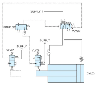
Valve Manifold Pneumatic Schematic. This is a screenshot of a pneumatic schematic for a valve manifold and the actuators it controls. Learn more about the specialized machines we can design for your unique process here.
Pneumatic Systems
Outline of Pneumatic Circuit Diagram Creation Program - Symbols corresponding to the product part number can be selected. - The circuit symbols in the library on the right side of the screen can be pasted using a simple drag-and-drop operation. - Piping drawings can be created automatically by simply clicking the piping port of the equipment.
Basic Pneumatic Circuits: White Paper
I think cascading method would be more applicable to books sorting machine. But I've not really seen the circuit diagram of the book sorting machine? Where can I find them, tried googling, but couldn't find one.

Typical Single Cylinder Pneumatic Circuits – FLUIDSYS ...
30.03.2020 ... Schematics for pneumatic circuits can be invaluable, but only if you know the symbology.

The schematic diagram of the electro-pneumatic circuit in the ...
A single acting cylinder has one pneumatic port to fill and empty the air chamber. The cylinder moves in one direction by filling the air chamber, and returns by spring force. The 3/2-way valve either fills the air chamber or vents the chamber to the atmosphere. A basic pneumatic circuit for a single acting cylinder can found on the picture below.

Pneumatic systems - Engineering Drawing - Joshua Nava Arts
Read Book Festo Electro Pneumatic Circuit Diagram Cagavs nonlinear mechanisms, aerothermodynamics, pneumatic servo mechanisms, and high-speed pneumatic control theory.Detailing the major developments of the last decade, the Handbook of Hydraulic Fluid Technology, Second Edition updates the original and
Pneumatic Systems
This article deals with common Solenoid Valve and other Pneumatic symbols giving a detailed view of pneumatic circuit symbols and their meaning. Valve symbols including Solenoid Valve Symbols are those that are in common use. UK Free : 0800 808 7799 Int : +44 Reading Pneumatic Schematic Symbols. Hydraulic and Pneumatic P&ID Diagrams and Schematics
Basic Pneumatic Circuits: Part 2 of 2 | Modern Pumping Today
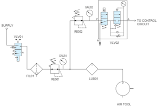
Figure 1: Air Prep Circuit Diagram: A good design practice is to include an air preparation circuit on any automated machine. Page 5. Basic Pneumatic Circuits: ...9 pages
Solved Fig 1 Shows a pneumatic circuit diagram used for air ...
TLDR: Can anyone point me in the right direction for a headlight circuit diagram for a 2018 SR5 with halogen lights? Specifically looking for the high beam circuit. Added an aftermarket lightbar with a relayed switch. Switch is currently powered 100% of the time. Would like to tap into the highbeam circuit, ideally inside the cab, to supply power to my switch... so I can only turn the light bar on when the highbeams are on.
How to Design Efficient Pneumatic Systems | Clippard ...
... design of the circuit follows the idea of exhaust reutilization. Starting from the perspective of closed circuit, a small-sized commutating air compressor ...

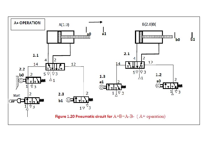
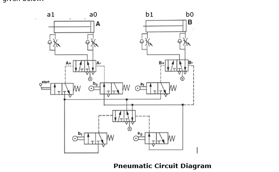
13 Draw the pneumatic circuit diagram on the data sheet State ...
Pneumatic systems, called circuits, are used extensively by engineers to power and control robotics. Engineers design pneumatic circuits to perform activities in manufacturing and other industrial applications that require repetition and consistency. One of the most common applications of pneumatics used by engineers is safely controlling a ...
Reading fluids circuit diagrams - pneumatic circuit examples
These ece mini projects kits come with a circuit diagram and video tutorials to help you understand the development along with 3 different kit types as per your need. With detailed video tutorials our ece mini project kits help you understand how to start with practical electronics development and grow in the field.

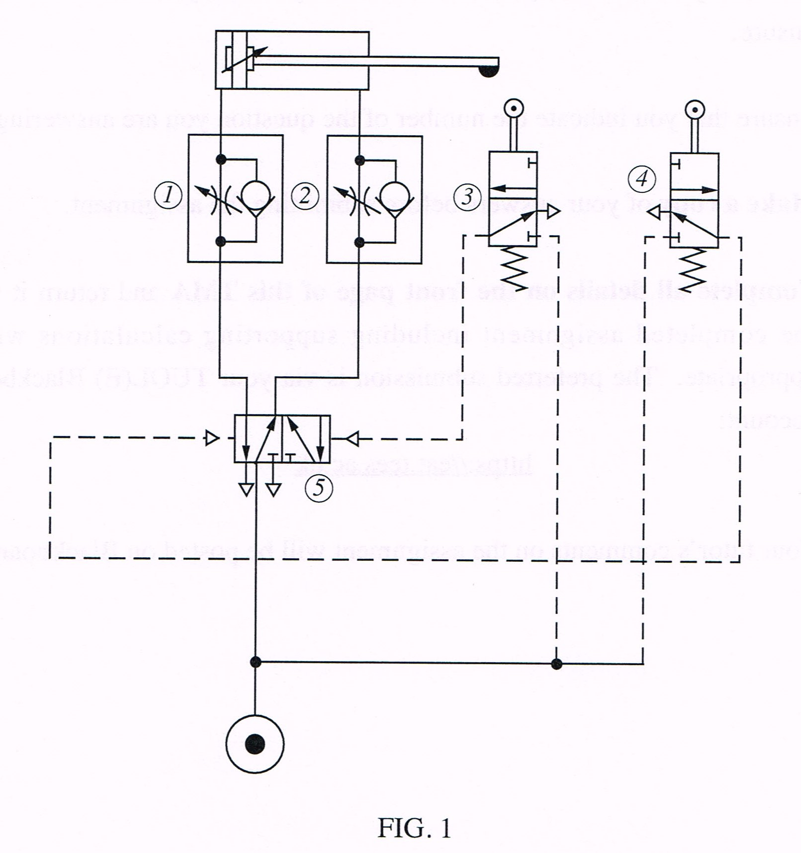
Pneumatic circuit diagram. | Download Scientific Diagram
This video will explain how to read and understand pneumatic schematics diagram . It covers single and double acting cylinders, ...
Chapter 5 Pneumatic System Multi Actuator Circuit Prepared
Sep 27, 2021 · A free and powerful circuit designing software. FluidSIM is a robust application designed to help you create, simulate, and study digital, electro-hydraulic, electro-pneumatic, and electronic circuits.The free application combines the power of a circuit diagram editor with component descriptions, photos,
Pneumatic Systems
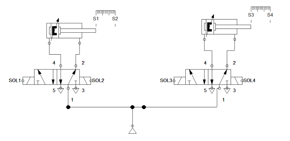
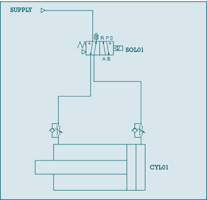
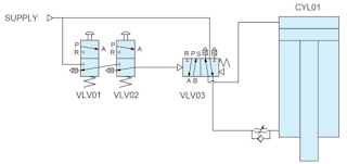
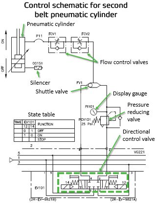
13.10.2021 ... The schematic below shows a common automation application: using a 4-way solenoid valve (SOL01) to extend and retract a double-acting cylinder ( ...
4 Basic Pneumatic Circuits | Power & Motion
The Schematic Diagram Boolean Equation And Truth Table Of A 2 1 Scientific. Four Possible Circuits For 2 To 1 Mux Circuit A B And C 2t Scientific Diagram. Design And Simulation Of High Performance 2 1 Multiplexer Based On Side Contacted Fed Sciencedirect. 7 3 Multiplexers Introduction To Digital Systems Modeling Synthesis And Simulation Using ...
Design Of A Pneumatic Valve For Automatic Seat Lifting Or ...
Mar 29, 2019 · How Does Elevator Works, Circuit Diagram & Types March 29, 2019 By Dave Due to the improved control structures, hardware and other automation systems in traction elevator systems, most of the manufacturers are producing energy-efficient elevators.
Low Cost Automation Tutorial | Technical Tutorial - MISUMI
Advertisement By: Marshall Brain Here's a circuit diagram for the power supply and time base. As we saw in the article on electronic gates, the power supply is the most difficult part! Advertisement To create the rest of the clock you will ...
4 Basic Pneumatic Circuits | Power & Motion
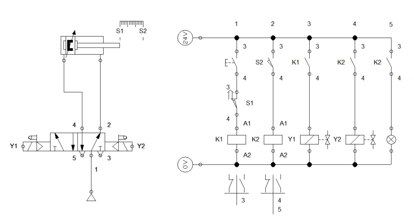
The electrical circuit diagram for in-direct control of a double- acting cylinder is shown in Figure. Indirect Control of double acting cylinder (using 5/2 way,
Electro-pneumatic Basic: Ejecting a workpiece (Interlocking ...
Pneumatic Valve Positioner Working Principle The Pneumatic Valve Positioner is an instrument working on force balance principle to position the Control Valve stem in PDF A Regulator in a Circuit Pneumatic Circuits. Pneumatic power converts electric energy to mechanical energy using compressed gasses instead of motors or electromagnets.
Pneumatic circuit diagram question | Physics Forums
Reading fluids circuit diagrams - hydraulic & pneumatic Circuit breakers can be reset manually or automatically to resume normal operation. Thermal protection circuit breakers are temperature sensitive, single and double pole, fixed time delay, push-to-reset or switch function, and a compact design. Magnetic and hydraulic operation circuit breaker

Basic Pneumatic Circuits - Tech Briefs
Pneumatic System Diagram. Here are a number of highest rated Pneumatic System Diagram pictures on internet. We identified it from reliable source. Its submitted by paperwork in the best field. We admit this nice of Pneumatic System Diagram graphic could possibly be the most trending subject behind we part it in google plus or facebook.

Design aids for pneumatics
SMC- Pneumatic Circuit Diagram Creation Program Outline of Pneumatic Circuit Diagram Creation Program - Symbols corresponding to the product part number can be selected. - The circuit symbols in the library on the right side of the screen can be pasted using a simple drag-and-drop operation. - Piping drawings can be created automatically by ...

Pneumatic circuit (Circuit no. 1) Control of Single acting cylinder.. #30kviews #viralvideo #circuit
FluidDraw S5 is an application for creating pneumatic circuit diagrams. The program provides the standard circuit symbols and all of the components contained in the Festo product catalog along with their part numbers and technical details. It also supports DXF files and circuit diagrams created with older FluidDraw versions and the FluidSIM ...
ELECTRO-PNEUMATIC
Design a pneumatic circuit diagram for the components you selected and test its function via simulation. A control system is to be designed for this purpose. The actual one-way flow control valve must also be adjusted to get the actual cylinder to advance more slowly.

Tutorial 5 - Electric and pneumatic circuits - User Manual
Pneumatic; Pneumatic Misc; Pneumatic Pumps, Cylinders and Motors; Pneumatic Valves; Prefab Circuits; Reports; Rockwell Automation; ControlLogix 5570 PLC CPU Modules - Layout; 1756 ControlLogix PLC AIO Modules; 1756 ControlLogix PLC AIO Modules - Layout; 1756 ControlLogix PLC Contact Modules; 1756 ControlLogix PLC Contact Modules - Layout; 1756 ...

Pneumatics Hydraulics Solenoid valve Pneumatic circuit ...
... set up of the electro-pneumatic drive with FluidSIM ® system is as shown in Figure 2. A schematic diagram of the electro-pneumatic control system ( ...

Experimental analysis of electro-pneumatic optimization of ...
Hello, I’m very new to circuit design and I’m trying to copy a circuit on a pcb that I have into a circuit diagram so I can better understand it. Doing this has been extremely hard. I’ve just been trying to copy over the exact trace layout onto a piece of paper but i’m unable to mark the components and it’s extremely messy. Should I suck it up and just try harder or is there an easier way to do this? Thanks

Experimental analysis of electro-pneumatic optimization of ...
Identify pneumatic symbols. Draw a pneumatic schematic from the actual circuit connections on the machine. Connect a pneumatic circuit given a schematic. Design a multiple actuator pneumatic circuit. Use software to simulate a pneumatic circuit. LAP 3. Principles of Pneumatic Pressure and Flow. Calculate the extension force if a cylinder given ...
Reading fluids circuit diagrams - pneumatic circuit examples
Reading Pneumatic Schematic Symbols - Gears EdS Continue reading. Automobile Automobile Servicing Four Wheeler (certification with TUV) Pneumatic Circuit Designing. Pneumatic Symbols as per ISO5599. Analog and Digital Custom IC design Course title: Custom Analog IC design. Schematic design. System used Cadence Virtuoso design environment and ...

PNEUMATIC CIRCUITS. - ppt download
Anyone who enjoys crafting will have no trouble putting a Cricut machine to good use. Instead of cutting intricate shapes out with scissors, your Cricut will make short work of these tedious tasks. A Cricut machine is a die-cutting machine ...
Solved Briefly explain the operating sequence of the | Chegg.com
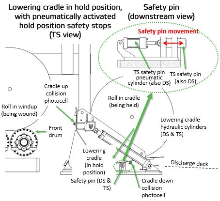
This article describes two example pneumatic schematic diagrams: winder lowering cradle safety pins and winder belted threader operation.
How to Design Efficient Pneumatic Systems | Clippard ...
computed. The mathematical equation is developed as a block diagram in Simulink by developing this Simulink model, which can be simulated and test the systems behavior. Controller design involves design of the schematic flow of the controller system and actuator's pneumatic circuit is designed. The
Pneumatic Circuit Symbols Explained |Library.AutomationDirect
Circuit symbols are used in circuit diagrams (schematics) to represent electronic components. This article deals with common solenoid valve and other pneumatic symbols giving a detailed view of pneumatic circuit symbols and their meaning. A coil of wire which creates a . The relays are switching electrical devices that are activated by signals.

PLC Pneumatic Circuit Control | PLC Programming Pneumatic System
I am trying to make a magic system which relies on magic circles, magic language, grimoires, geometry, etc... for a game. So I want to be a bit puzzle-like, easily understandable yet quite versatile. My idea was to make them like Electronic Circuits, with a magic source representing a battery or an AC source, some parafernalia in the middle that transforms magic energy into other types of energy(maybe elemental magics since I want my system to be elemental) then ground it. Since Electron...


Comments
Post a Comment