38 turbo vacuum line diagram
Specs- 350 engine, Edelbrock Performer EPS manifold, Holley 4160, TH350 trans (rebuilt w/shift kit), 3.73 posi. I stopped at the transmission place that rebuilt my transmission about a year ago. They looked at it and said the vacuum line should be connected to a vacuum port directly on the manifold, ie. the same one that the brake power booster ... Quick video showing how and where to connect your turbo vacuum lines
Got a Saab 2.0T the plastic hose running between the vacuum pump and the underside of the intake manifold is soaked in oil and oil drips like a runny nose from the intake manifold. Aside from cleaning/replacing that plastic line, what else should I investigate?
Turbo vacuum line diagram
I have a 98 Dodge Ram 2500 turbo diesel I’m looking sell in California. The vacuum line which runs from the engine to the cab, which controls the AC vents, broke off. To fix it I would have to remove the dash and replace the line. And also during this process I’d have to replace the dash top cause it’s in about 5 prices currently. My question is, I’m not sure if the truck will pass smog with a broken vacuum line? It doesn’t need to be smoged till March, but I’m not sure about this stuff.... So I have an update. I spent some time tracing the vacuum hose routing in the car, and comparing it to the VW Vacuum Hose Routing Diagram. In my first post I mentioned a 'stray' hose that was disconnected, and as it turns out the hose is not on the diagram. On closer inspection, it originates from a T-Piece in the N75 to VNT Actuator Line. from throwing CEL and plug the port of the evaporative. canister hose on the turbo inlet hose after you remove the. canister. The boost gauge may be ran off the "P"port of the. throttle body or the FPS line. Also found the diagrams for the 1g-. 1g Before and normal vacuum wiring:
Turbo vacuum line diagram. FINALLY, a Vacuum Hose Diagram Topic is solved. This is for a '98 T-5. Others will vary but the same or similar to most 850 turbo's. The designed changed with later S/V/70's so be aware. I got so darned frustrated trying to see this intsy bittsy diagram under the hood of the car, so I finally took a decent digital picture today. 1994 Ranger Sport, OBD-1 2.3L 4-cyl with 5-speed, 138xxx miles. I've been squashing bugs in this thing since I bought it last year (mostly via firing the parts cannon at it, she had a rough previous life) and I'm almost there. I think I have a vacuum line plumbing issue, and information on Google has been scant. On the lower part of the intake plenum (the "octopus" vacuum distribution tree), I believe my plumbing is correct. But the line that runs from the crankcase vent canister (drivers' sid... Vacuum Diagrams This is not an automated service. Each Diagram that is requested has to be hand selected and sent. As this is a free service it receives an overwhelming amount of requests and may take up to a week or longer for a response. Hi everyone, I just bought a used turbo inlet and noticed that there is a [screw](https://imgur.com/a/crxAwbM) off the vacuum line to the boost controller. Is there a reason for blocking it or should I just find a way to open it up? Thanks in advance!!
MINI factory OEM replacement Vacuum Line to the Turbocharger. Fits the following Cooper S models with the N14 engine: 2007-2010 R56 MINI Cooper S Hardtop 2008-2010 R55 MINI Cooper S Clubman 2009-2010 R57 MINI Cooper S Convertible. Also compatible on JCW models with the N14 engine (2008-2012). For a complete listing of Turbo related parts, click ... 93 Legend L Coupe. It's a decent diagram, but I don't care for one thing: the wastegate line shouldn't be running that far. If you tap the wastegate line closer to the turbo, you will have better boost control and throttle response. Running feet of vacuum hose inscreases the mass of air that has to be moved in order to move the wastegate diaphram. Hi guys, where can I find the diagram for 2012 CLC engine 2K caddy Thanks Feb 28, · SRT-4 vac line set up is this the proper way to set them up on stock turbo stock blow off valve with blue rice plate. Factory Vacuum line diagram for Dodge SRT July 13, MP Blog admin. We've had a lot of customers call and ask how the factory vacuum line should run on their Neon SRT-4's.
Im looking for a vacuum line diagram for a 1998 Jeep Grand Cherokee Laredo. It's a 4.0 engine if that makes a difference. I think im having an issue with my heat due to a vacuum line. When I have it set on feet and top vents it blows from the deforst vents too. Same of I have it set to just the feet vents, it'll blow from both FUEL-15, Fuel and Vacuum Line Diagram (944 Turbo) Introduction The following fuel system line diagram includes most of the vacuum line routing for 944 Turbos. If the vehicle is equipped with an active carbon tank for fuel tank venting, there will be additional vacuum line routing for that system. Routing for these lines is similar 2011+ Engine Related Questions - Ecoboost Vacuum line diagram - Just replaced the timing chain on my 2011 Ecoboost and didn't take pictures of the engine prior and now am missing some vacuum connections. Anybody have a diagram or know of a manual that will have that detail? Feb 22, 2019 — I need to know how to run my vacuum lines: I have a turbo, external precision 46mm... ... Here is a diagram of basic wastegate plumbing.6 posts · I've been told so many thing and I'm sorry this topic is so used. I need to know how to ...
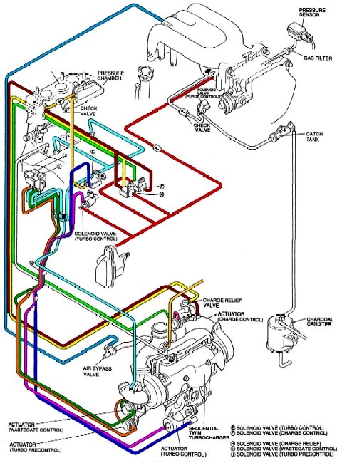
Vacuum Diagrams(Stock, Simplified Sequential, Non-sequential ...
Does anybody know where I can get a vacuum line diagram for my 94 5.0 in an f150? I’ve looked everywhere on the internet and all I can find is Mustang. Are they the same? I even bought a service manual from o’reilly’s and it had everything except that in it. Every bit of help is appreciated.

Turbo install, vacume lines??? - Scionlife.com
With the proper name and appropriate year/vacuum schematic (I have these) we can all put ours cars back together properly. Here's a list of all the items I think I need to identify on my 1980 Ghia Turbo, manual, California car, with A/C. #1RNR - No. 1 Runner (Intake Mani, metal vacuum lines) #4RNR - No. 4 Runner (Intake Mani, metal vacuum lines)

Vacuum lines - whatwazithinking
Sorry for the long list of questions. I have a focus st and the previous owner made the turbo flutter and I was wondering because there is a vacuum line going from the Symposer delete to the HKS BOV. If this is damaging the turbo I want to take it off. Thank you for reading
Determining Correct 1980 to 1985 Diesel Vacuum System Hose ...
HOW TO RUN VACUUM LINES FOR WASTEGATE & BLOW OFF VALVEPayPal Donate https://paypal.me/duwop77?locale.x=en_UST-Shirts-https://teespring.com/stores/duwop77-3In...

turbo hose diagram Questions & Answers (with Pictures) - Fixya
14,274 Posts. #3 · Oct 18, 2011. There's a couple of problems with that. The Green line goes to the rear nipple where you have the Blue line. The Blue line doesn't go directly to the turbo housing as your diagram indicates, it goes to a T just before the turbo housing. The other leg of the T leads to the vacuum ejector.

Diagram of the vacuum system for the beam profile monitor ...
Is there a diagram that shows how the vacuum lines hook up for the 2.5 Turbo ? Vacuum hose routing-1989 2.5L California Turbo I engine Vacuum hose routing-1990-91 2.2L and 2.5L Federal engines with manual transaxles, and 2.2L and 2.5L Canadian and California engines
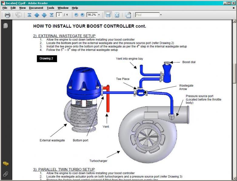
How to install vacuum lines to manual controler and external ...
Hello everybody what I need right now is a guide to help me find and trace out where the vacuum lines all of them are supposed to go across and on the 5.4 V8 1999 F-150. I had started working on my '02 about a year and a half ago and replacing things and after that stimulus check I got a second 99 f150 and started swapping working parts to my 2002. Up until two Saturdays ago I totalled My 02 f150 and now my original parts truck looks like my might be my only driving option. However, The vacuum ...

Volvo 850 T-5 T-5R & Turbo vacuum diagrams | Volvotips
Hi guys I have a 2004 CRV and getting a P0172 and will stall whenever coming to a stop sometimes. Next on my list to check is a vacuum leak but w/o a diagram I have no idea where to look. I've tried searching online but cannot find anything. Does anyone have a diagram or can take a picture of their 2nd gen and mark out all the vacuum lines as a reference when I check for a leak. Thanks in advance.
Please help with vacuum lines - North American Motoring
Here is a little diagram I had done for some of the other members here for their vacuum setups. *SOLD* St00pid Tuned 06' RSX Type-S, Peakboost Turbo Kit w/ GT3076 Turbo de-tuned to 400whp & 280ft/lbs on pump :giggity:
turbo vacuum help | HondaSwap.com
That vacuum block is a prototype part, not a production turbo 3.8 pod. Also, the steel lines attached to it are prototype, not production. The production steel tubes were not triangle-clustered like yours.
Banzai Racing Vacuum Lines Replacement
Jul 25, 2002. #3. There is a larger steel line that points towards your DS fender, that is the vacuum source for EVAP cannister purge. The other two lines should be the same size, and either one can go to the EGR solenoid and the other to the the FPR. The big port off of the vacuum block goes to the PCV valve.
Vacuum line for my turbo/wastegate | Newbie and Basic Turbo ...
Wiring & Vacuum Diagrams...and much more!! This product includes - Colorized wiring diagrams - Vacuum diagrams - Vol. III 1972 Car Shop Manual, Electrical - Electrical Illustrations - How to Read Wiring Diagrams training course 5236 Licensed and approved by the Ford Motor Company 1972 Free Bonus! 30-Minute Video Ford Training Course 13001, Vol ...

Turbo Vacuum line routing diagram by cthan3o3 | Honda D ...
240 Posts. #5 · Apr 2, 2015. ffsvtt44 said: Looking for a diagram for vacuum lines for turbo build everything is in the car but I'm in need of help on how to run lines my setup he's an external WG and a turbo with no vac source on turbo outlet also installing a manual boost controller and input would be helpful.
Turbo Wastegate Vacuum Line Question | Mercedes-Benz Forum
Vacuum Hose Diagrams - 1994-2000 FWD Turbos. Post categories. In Boost, Turbo & Intercoolers, Volvo 850, Volvo C70, Volvo S70 & V70 1998-2000, Volvo V70 R 1998-2000.

Turbocharging for Dummies – DriverMod
Vacuum Line Routing for 231 3.8 Liter Turbo. Here's a handy schematic of how the vacuum lines get routed on the 3.8 liter turbocharged motor found in 1986-1987 Buick Turbo Regals. . . Related Stuff: vacuum line sizes. wastegate/boost controller vacuum lines. . Tags: 1986 1987 231 3.8 vacuum line.
Help! Vacuum hose routing to airbox | The Lotus Cars Community
I can’t seem to find one for my 2006 a4 2.0t i’m replacing the turbo with new seals and all that but can’t remember where they all go exactly and i don’t wanna put a cooling like where the oil should be i need help baddd

Distributor vacuum lines/smog removal - Pelican Parts Forums
Actually I had done the same thing on my 2005 Outback XT which has the same engine layout as the 09+ Foresters and I wanted to reuse my Bluch 20g turbo. I used a lot of the diagrams on Legacygt.com, but it looks like those links arent valid any more. I have these two PDF's and I'll see if I can find others.

Vacuum Diagram For Evo X | PDF | Turbocharger | Throttle
turbo vacuum line help. Im in need of a diagram or something to direct me on where the vacuum lines and boost lines go. If anyone can help that'd be appreciated. I'm not hitting any boost right now cause they're All mixed up * Registered users of the site do not see these ads.

Volvo 850 T-5 T-5R & Turbo vacuum diagrams | Volvotips
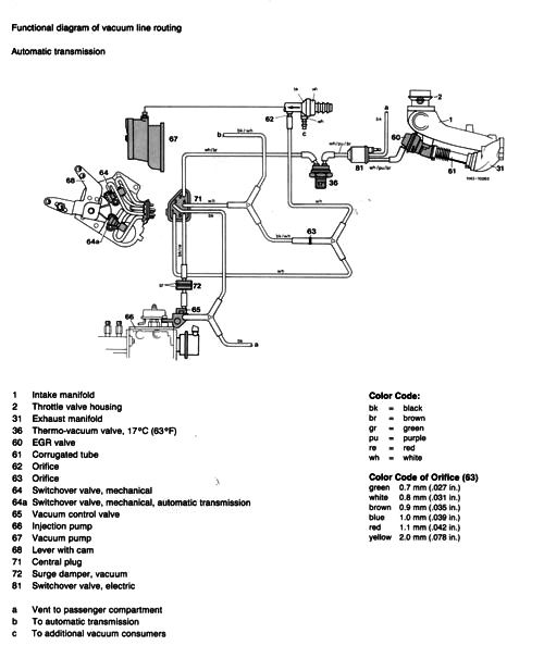
VACUUM DIAGRAMS 944 TURBO One of the most common problems we find with the 944 Turbo is vacuum line related, whether it's old and leaking hoses, or mistakes in the plumbing of your updated vacuum lines. We have Vacuum Hose Kits to replace those old lines and recommend doing so. Below are several diagrams that should aid you in the correct ...
Dont understand the vacuum hose configuration!! - Rennlist ...
first you must recover the freon from the system then change the line always installing new orings, evacuate the system "which means to put it into a vacuum to remove all the air and moisture out of the system" then recharge and enjoy....on your turbo pt it calls for .3 for the job ...anyone should be able to do it in like 30-40 min. proved you have the right tools...recovery machine and so on

2005 2.5 Turbo Vacuum Lines Diagram | SwedeSpeed - Volvo ...
I am trying to clarify how my [our] car's turbo vacuum lines are run vs how they should be. I have found some parts diagrams across the web, but would prefer to get details from someone first hand. Can someone(s) with a bone stock n54 335i confirm that this diagram is the proper factory...

Porsche 944 Turbo vacuum line routing sketch for Lindsey ...
FINALLY, a Vacuum Hose Diagram. This is for a '98 T-5. Others will vary but the same or similar to most 850 turbo's. The designed changed with later S/V/70's so be aware. I got so darned frust.

S401 Hose 10 Mod – Tastes Like Petrol
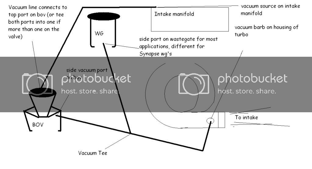
Turbo Waste Gate Solenoid Boost Pressure Vacuum Lines Connection Routing. When you are connecting the vacuum lines to/from your turbo, there's a few different ways to do it, depending on what else you have connected to the turbocharger. Waste gate, solenoids, etc., will determine how you go about accomplishing this task.

Yea...another Vacuum Line discussion but with a pic ...
from throwing CEL and plug the port of the evaporative. canister hose on the turbo inlet hose after you remove the. canister. The boost gauge may be ran off the "P"port of the. throttle body or the FPS line. Also found the diagrams for the 1g-. 1g Before and normal vacuum wiring:
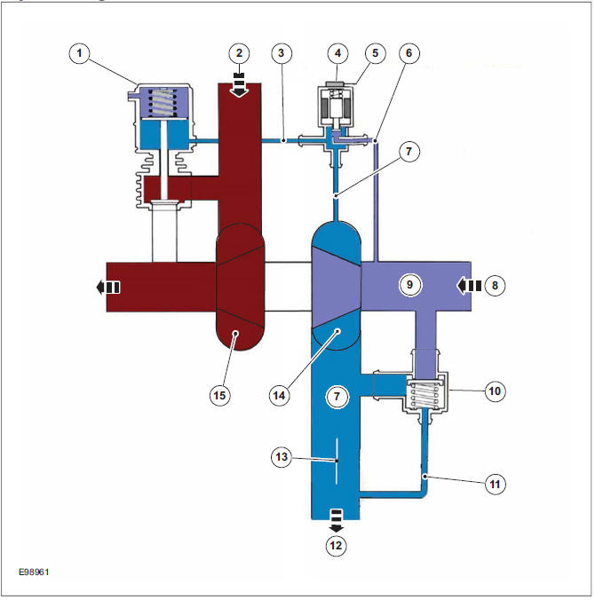
Ford Kuga: System Diagram - Turbocharger (System Operation ...
So I have an update. I spent some time tracing the vacuum hose routing in the car, and comparing it to the VW Vacuum Hose Routing Diagram. In my first post I mentioned a 'stray' hose that was disconnected, and as it turns out the hose is not on the diagram. On closer inspection, it originates from a T-Piece in the N75 to VNT Actuator Line.
LINDSEY RACING - Your Porsche Performance Parts Center ...
I have a 98 Dodge Ram 2500 turbo diesel I’m looking sell in California. The vacuum line which runs from the engine to the cab, which controls the AC vents, broke off. To fix it I would have to remove the dash and replace the line. And also during this process I’d have to replace the dash top cause it’s in about 5 prices currently. My question is, I’m not sure if the truck will pass smog with a broken vacuum line? It doesn’t need to be smoged till March, but I’m not sure about this stuff....

Audizine Forums

all vaccum lines on v5-v6 wrx - NASIOC

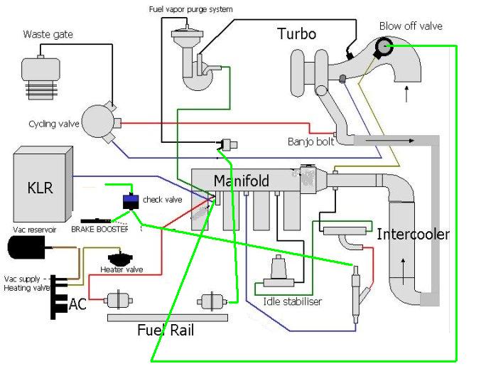
VACUUM HOSE PIPING DIAGRAM
4AGE vacuum line diagram anyone | MR2 Owners Club Forum

Nissan Skyline GT-R RB26 vacuum wastegate diagram - Nissan ...
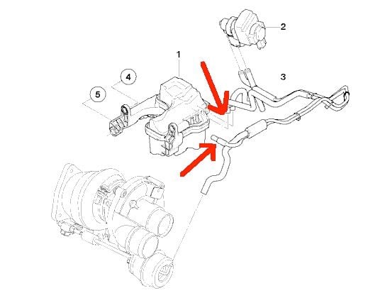
Help with Wastegate Vacuum Line! - BMW 3-Series (E90 E92) Forum

How do I set up vacuum between various turbo components ...
Collapsed vacuum hose + eractic idle please help ...
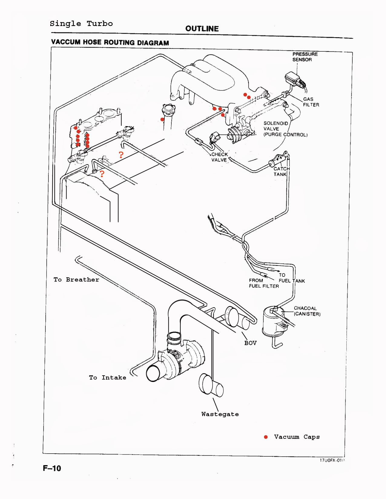
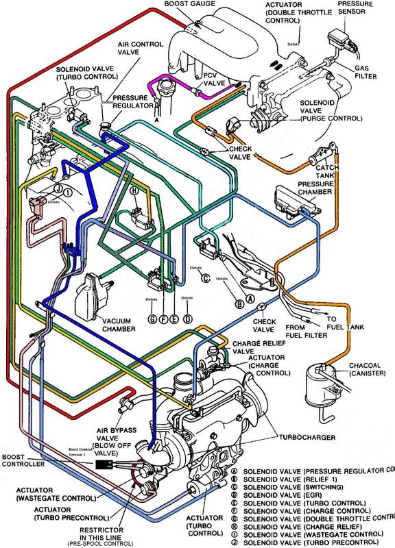
Single Turbo Vacuum Hose Diagram - RX7Club.com - Mazda RX7 Forum

Turbocharging for Dummies – DriverMod
Vacuum Hose Diagram | Mitsubishi 3000GT & Dodge Stealth Forum

Turbo Line Diagram | SwedeSpeed - Volvo Performance Forum


Comments
Post a Comment