38 what is a one line diagram
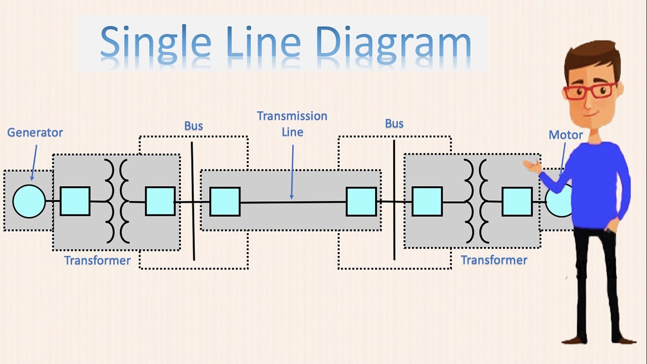
In this Video, we have demonstrated how to read and understand electrical Single Line Diagram also called as Power Flow Diagram.We hope this video is useful ... In power engineering, a single-line diagram ( SLD ), also sometimes called one-line diagram, is a symbolic representation of a three-phase electric power system. The one-line diagram has its largest application in power flow studies. Electrical elements such as circuit breakers, transformers, capacitors, bus bars, and conductors are shown by standardized schematic symbols.
Single Line Diagram Keywords Single Line Diagram , PG&E, simple diagram of the electrical path, the main components of the system, Meter, Service Panel, A/C Disconnect Manufacturer Model #, Solar Panels, Number of Panels, wind turbine, inverter,
What is a one line diagram
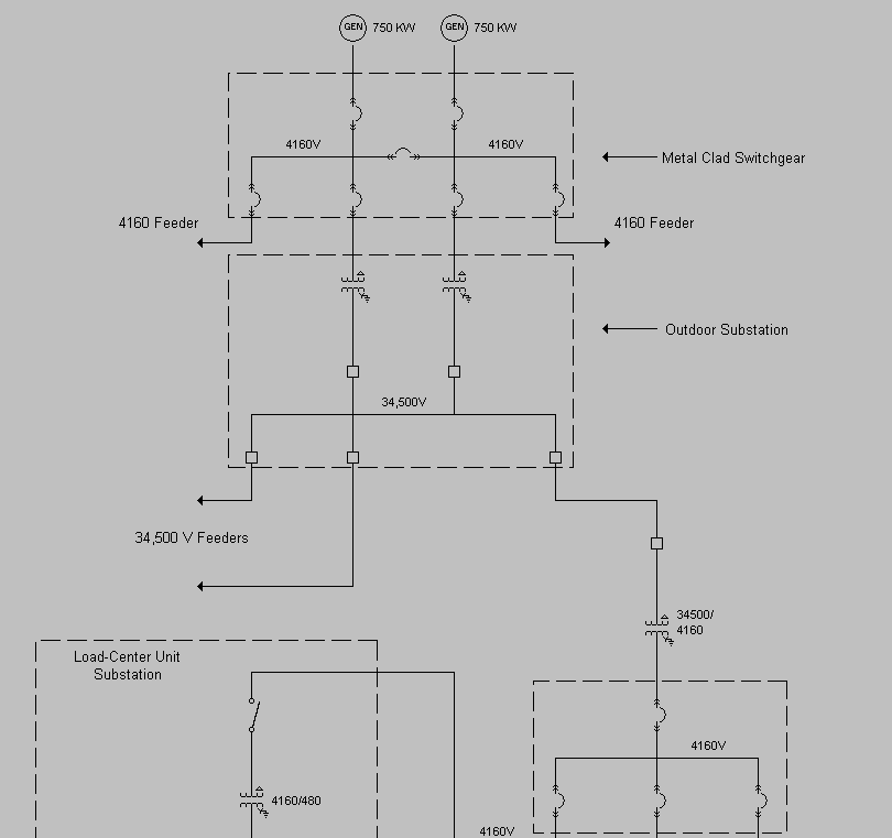
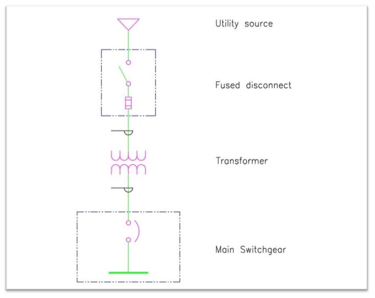
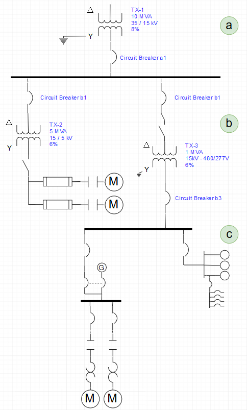
27/05/2021 · A single-line diagram (SLD) is a high-level schematic diagram showing how incoming power is distributed to equipment.. A4.1.1 Single-Line (One-Line) Diagram: A diagram which shows, by means of single lines and graphic symbols, the course of an electric circuit or system of circuits and the component devices or parts used therein. Lets go through a industrial single line diagram. When interpreting a single line diagram, you should always start at the top where the highest voltage is and work your way down to the lowest voltage. This helps to keep the voltages and their paths straight. To explain this easier, we have divided the single line into three sections. September 11, 2021 - Sometimes a a single line drawing or diagram of an electrical installation is also called a one-line diagram. In this article, we will briefly discuss what an electrical SLD is, types of electrical diagrams, the importance and benefits of a single line diagram.
What is a one line diagram. The one line is drawn and components of the system are shown at line. The main importance to use a single line diagram is to discuss the main parameters of the system and its elements. If we are discussing the load of the system then in case breakers and relays are not drawn on line since it has no importance but in case of there is transient ... Line diagram in statistics : When the data vary over time, we take recourse to line diagram. In a simple line diagram, we plot each pair of values of (t, y), "y" representing the time series at the time point t in the "t-y" plane. The plotted points are then joined successively by line segments and the resulting chart is known as line-diagram. Single line diagram (SLD) We usually depict the electrical distribution system by a graphic representation called a single line diagram (SLD). A single line can show all or part of a system. It is very versatile and comprehensive because it can depict very simple DC circuits, or a very complicated three-phase system. •Draw x-yyg y diagram and x=y line •Find the outlet and feed conditions known •DrawqDraw q-line •Draw upper operating line •Connect lower operating line •Step stages from know end conditions, and count stages
The single-line diagram is the blueprint for electrical system analysis. It is the first step in preparing a critical response plan, allowing you to become thoroughly familiar with the electrical transmission system layout and design. The single-line diagram also becomes your lifeline of information when updating or responding to an emergency. October 21, 2021 - In order to continue enjoying our site, we ask that you confirm your identity as a human. Thank you very much for your cooperation Don't minimize the importance of the single-line diagram on safety. Thomas Domitrovich, P.E., LEED AP, vice president, technical sales. Whether a building is old or new, electrical engineers depend on single-line diagrams (SLDs) to track the electrical components that assure proper maintenance and safety practices. Electrical riser diagrams is the diagram showing with the physical layout of the system. One line diagram will guide the electrical circuit configuration of the system. Upvote (0) Downvote (0) Reply (0) Answer added by Hussam Adnan, CPMgr, Maintenance Manager , Teeba Investment for Developed Food Processing Co. 7 years ago.
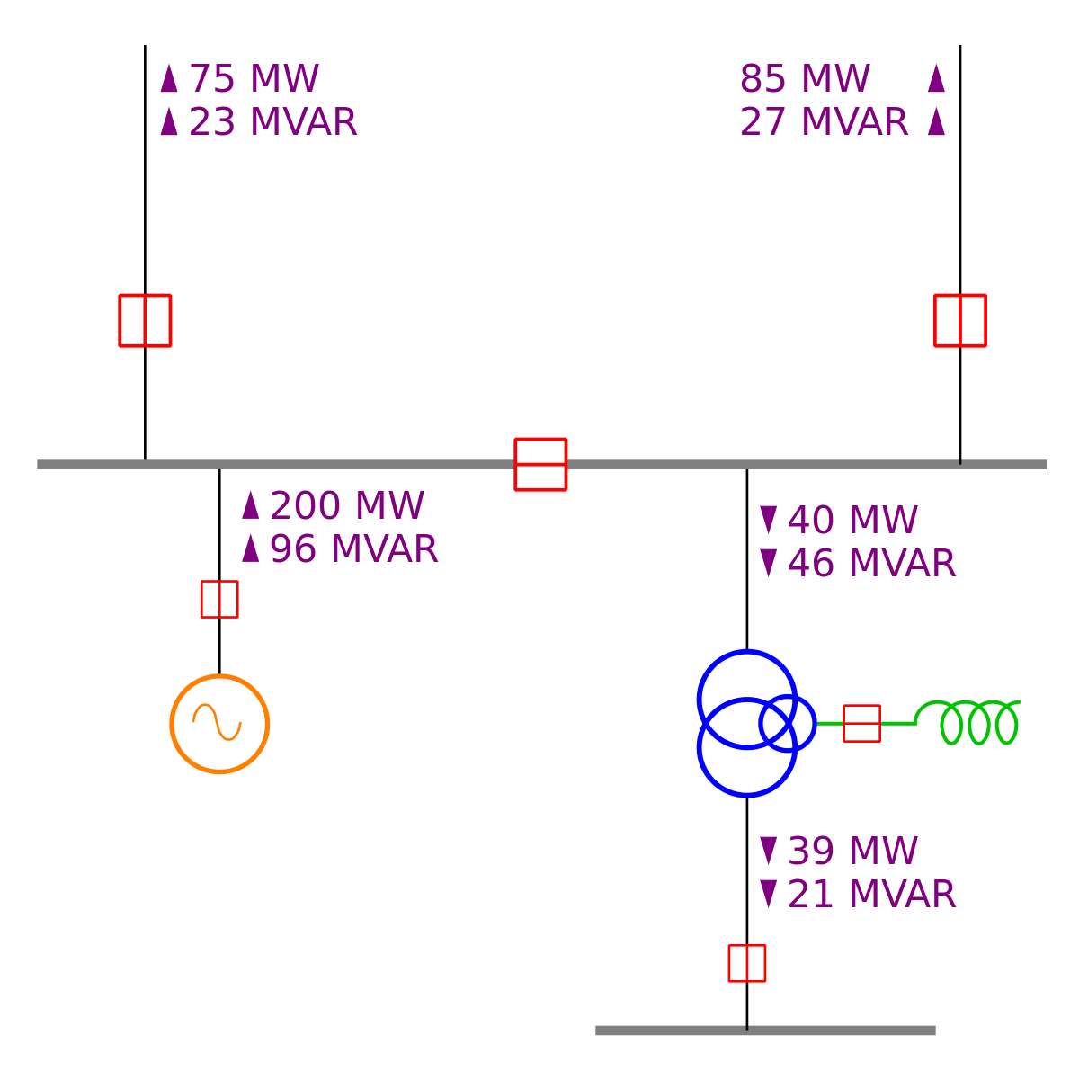
Single Line Diagram or One-line Diagram. Single Line diagram (SLD) or one-line diagram is the representation of an electrical circuit using a single line. As the name suggests, a single line is used to denote the multiple power lines such as in 3 phase system. One of the commonly used techniques for transmission system representation is a one-line diagram imposed on maps. In a zoomed out view, one-line diagrams only include a small number of high-voltage buses and transmission lines. Small arrows are plotted on the lines to indicate the direction of real power flow (in megawatts). The arrows point toward the direction … The architectural wiring diagram can be referred to as a one-line diagram. This is because the diagram shows multi-conductor cables with a single line. A single line drawn on these diagram wills always indicate at least two conductors. Single line diagrams like in figure 2 are used to illustrate the layout of buses in a substation. The arrangement of figure two is called a "breaker and a half". There are three breakers for every two connections of lines or transformers to the bus, i.e. 1 ½ breakers per termination. Fig. 3.
Types of Electrical Diagrams
Search Hammond Power Solutions · It is a simplified notation for representing a three-phase power system. The one-line diagram has its largest application in power flow studies. Electrical elements such as circuit breakers, transformers, capacitors, bus bars, and conductors are shown by ...

Electrical One-Line Diagram - archtoolbox.com
Electrical Symbols and Line Diagrams Chapter 3 Material taken from Chapter 3 of Electric Motor Controls, G. Rockis, 2001 One-Line Diagrams One-line diagram - a diagram that uses single lines and graphic symbols to indicate the path and components of an electrical circuit. One-line diagrams are used when information about a circuit is required

The Importance of Single Line Diagram (SLD) | Omazaki Engineering
The One-Line Diagram is a user-friendly interface to create and manage the network database used for schematic network visualization.
49 single line diagram
29/05/2021 · Electrical One-Line or Single-Line Diagram. An electrical one-line diagram is a representation of a complicated electrical distribution system into a simplified description using a single line, which represents the conductors, to connect the components. Main components such as transformers, switches, and breakers are indicated by their standard …
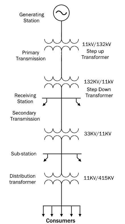
single line diagram of power system | One line diagram | power line diagram
Block flow diagram. The block flow diagram is also called a schematic diagram and it is a non-scaled single line diagram. This diagram is a simplified diagram of the piping system at the initial stages of the design process. The equipment in the piping network is represented by simple shapes such as rectangles, circles, etc.

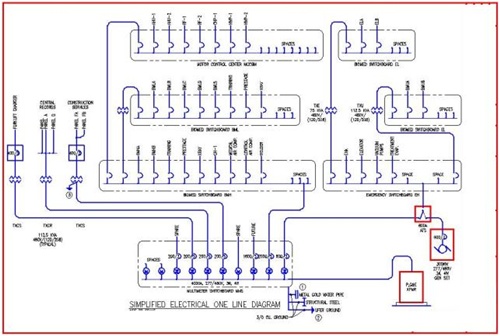
Simplified single-line diagram of the electrical system at ...
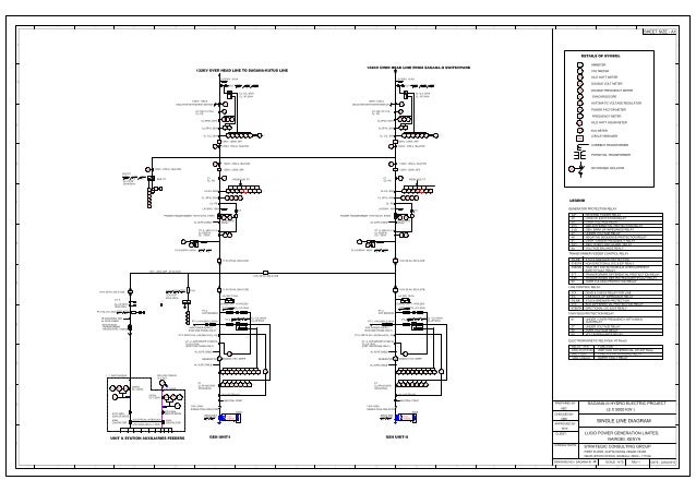
March 20, 2016 - Single Line Diagram During the preliminary project designing of any project,the key diagram used is the single line diagram (SLD) also called the one line diagram and a number of subsidiary signal line diagrams. The set of single line diagram form the basics of all electrical work carried out ...

One-Line Diagram - an overview | ScienceDirect Topics
Definition: Single line diagram is the representation of a power system using the simple symbol for each component. The single line diagram of a power system is the network which shows the main connections and arrangement of the system components along with their data (such as output rating, voltage, resistance and reactance, etc.).

One-Line Diagram - an overview | ScienceDirect Topics
Basics 3 4.16 kV Bus 1-Line : Basics 4 600 V 1-Line : Basics 5 480 V MCC 1-Line : Basics 6 7.2 kV 3-Line Diagram : Basics 7 4.16 kV 3-Line Diagram : Basics 8 AOV Elementary & Block Diagram : Basics 9 4.16 kV Pump Schematic : Basics 10 480 V Pump Schematic : Basics 11 MOV Schematic (with Block included) Basics 12 12-/208 VAC Panel Diagram
One-Line Diagram
Single Line Diagram. In this course we will learn in detail about SLD's or Single line diagrams. We will learn how to read and understand and extract information from a single line diagram. By the end of this course, you will be able to easily interpret a single line diagram. Let us have an overview of our course on Single Line Diagram.
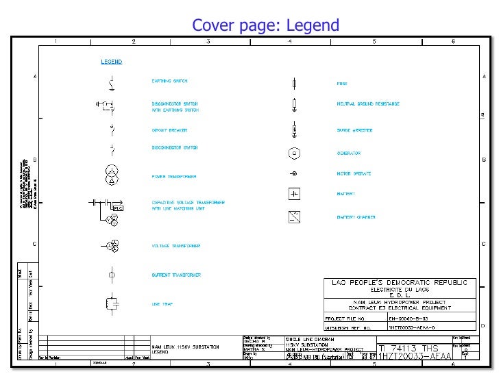
Line diagram of substation in AutoCAD | CAD (225.73 KB ...
August 4, 2020 - The electrical installation of a house or building is one of the key points of its structure. For representing it, it is common used the single-line diagram
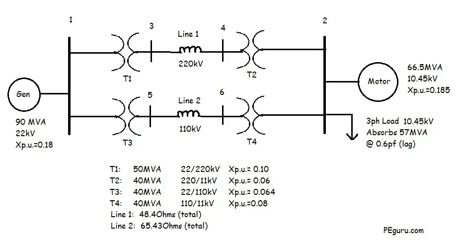
Per Unit System - Practice Problem Solved For Easy ...
November 1, 2017 - It is the general procedure to use single line diagrams for representing three-phase systems. When analysis is done using symmetrical components, different diagrams may be drawn that will represent the electric circuitry for positive, negative, and zero-sequence components.

Single Line Diagrams | Electrical Standard Symbols | PAKTECHPOINT
The single line diagram is circuit diagram where "one-line" is shown to represent three phases of a three phase power system. In addition to showing the ratings and size of electrical equipment and circuit conductors, a properly drawn one-line diagram will also show an electrically correct distribution of power with respect to current flow from the power source to the downstream loads or ...

Single Line Diagram (SLD) | alinea-sinadra
The one line diagram (also called single line diagram or drawing) is the electrical system drawing that shows the main items within the solar system and how ...
Step1 Single Line Diagram
Jun 21, 2019 · A single line diagram, also referred to as a one-line diagram, is usually a single page document that represents a facilities electrical distribution infrastructure. It will have one single line shown for bus (or cable) to represent all three phases.

One-Line Diagram - an overview | ScienceDirect Topics
December 31, 2019 - What is a three line electrical diagram? What does it differ from one line diagram? I started for a volunteering for a foundation who installs solar systems. During the installation, we were looking at one line diagrams and they told that we will need three line diagrams for the permit process.
What is one line diagram? - Quora
May 14, 2021 - The information from one line diagram can be widely used to enhance the performance of service activities. 4. The single line diagram can be termed as building an electrical system. ... 1. As we know that the single line diagram is a simplified way for representing a 3 phase power system, so ...

One-Line Riser Diagrams
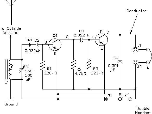
►Find more details, circuit schematics and the source code here.A one-line diagram or single-line diagram is a simplified notation for representing a three-p...

Engineering Photos,Videos and Articels (Engineering Search ...
Electrical One-Line Diagram. ETAP One-Line Diagram / View is an intelligent user-interface to model, validate, visualize, analyze, monitor, and manage electrical power systems, from high to low voltage AC and DC networks. It is designed to interactively model, monitor, and manage electrical networks as well as execute simulation scenarios and ...
Single-line diagram - Wikipedia
Elements on the diagram do not represent the physical size or location of the electrical equipment, but it is a common convention to organize the diagram with the same left-to-right, top-to-bottom sequence as the switchgear or other apparatus represented. A one-line diagram can also be used ...

How to Read a Single Line Diagram | Power Solutions | EECO
Transcribed image text: Q/ What does this mean in an electrical single line diagram? L1 11kV 50Hz 3PH 3 WIRE 2000A 4OKA FOR 1 SEC. 100kA PEAK L2 L3 1 1 52 MECHANICAL TRIP FACILITY 1 VCB 7 PV100 1250A 12kV 1 40KA T ES MECHANICAL IN TERLOCK (NOTE 4) EARTH SWITCH SURGE ARRESTERS
Intelligent One Line Diagram | Electrical Single-Line Diagram ...
Single Line Diagram Symbols. September 26, 2021. September 3, 2021. Single line diagram symbols is fundamental elements to indicate power distribution system including necessary information for the electrical equipment, protection and monitoring to be employed in the power generation distribution. Categories. Design Consideration, Engineering.
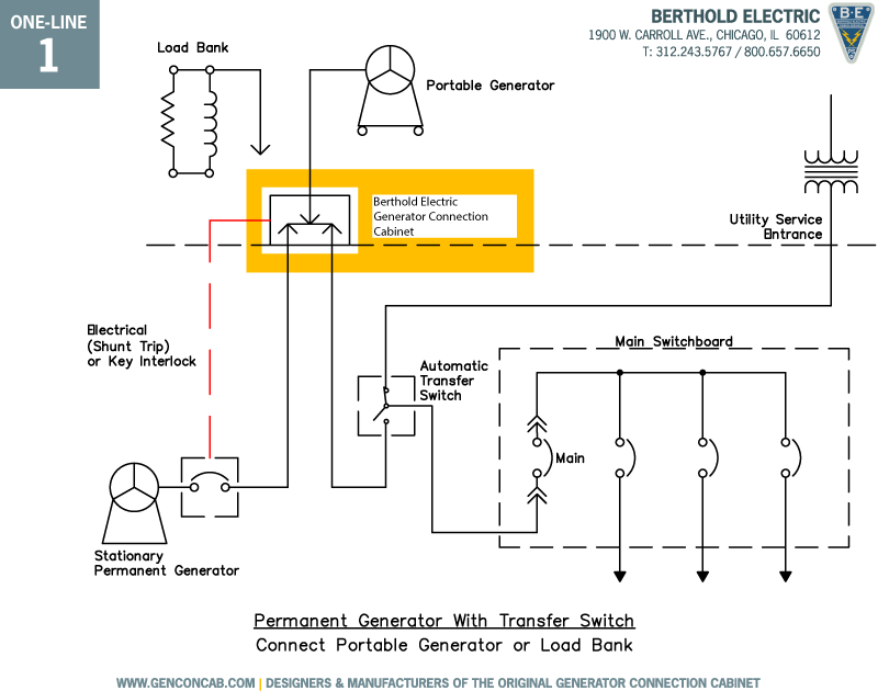
Generator Connection One-line Diagrams | Berthold Electric
Also called one-line diagrams, these drawings show the flow of electrical power or the course of electrical circuits and how they are connected. Physical relationships are typically disregarded in a single-line diagram, however they should show all of the major components in the power system and list all important ratings.

How to Read a Single Line Diagram | Power Solutions | EECO
SINGLE LINE DIAGRAM: As a layman View, SLD is nothing but consisting of various components of the Electrical System like, Transformer, DG, Panels consisting of HT Breaker, LT Breaker, CT, PT ...
The 7 Steps to Complete an Arc Flash Analysis
Single-line diagram representation: Note how much simpler and "cleaner" the single-line diagram is compared to the schematic diagram of the same power system: each three-conductor set of power wires is shown as a single line, each transformer appears as a single primary winding and single secondary winding (rather than three of each), each ...

Electrical One-Line Development - Power Systems & Controls
An electrical single line diagram abbreviated as SLD is also referred to as a one-line diagram. It is a simplified drawing of the whole system or a portion of the power system that shows the electrical placement of all major equipment. A single line diagram is a simplified explanation for representing a three-phase power system.

Fire fighting system for building: Single line diagram of ...
June 25, 2021 - A line graph connects individual data points that, typically, display quantitative values over a specified time interval.

The Importance of Single Line Diagram (SLD) | Omazaki Engineering
A single line diagram is a roadmap of the main components of your electrical system. It uses single lines and graphic symbols. These illustrate the course of an electric circuit or system of circuits. The diagram includes the component devices or parts used in the circuit. It includes all redundant and spare equipment in the system.
How to Make a Single Line Diagram — Leaf Electrical Safety
One of the key tools in developing and documenting an electrical power system is the Single Line Diagram (shortened SLD). The essentials of designing MV/LV single line diagrams (symbols & drawings analysis) Single line drawing starts with the incoming power source from the utility service and/or on-site generation and their associated ...
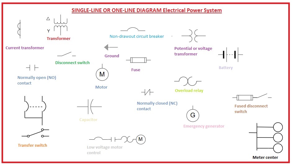
SINGLE-LINE OR ONE-LINE DIAGRAM Electrical Power System - The ...
A one-to-one function is a function of which the answers never repeat. For example, the function f(x) = x + 1 is a one-to-one function because it produces a different answer for every input. An easy way to test whether a function is one-to-one or not is to apply the horizontal line test to its graph.

How to Make a Single Line Diagram — Leaf Electrical Safety
A one-line diagram is a simplified graphical representation of a three phase power system, used extensively in power flow studies. In power engineering, one can make the assumption that the three phases of a system are balanced and can therefore be examined as a single phase. The assumption can be made because what happens on one of the three

SINGLE LINE AND BLOCK DIAGRAM | dithamaryani
Straight-Line Diagrams Online GIS Web Application offers the public a means of searching for SLDs by district, county, roadway description or by selecting a roadway using the map interface. County Section Number Key Sheet Manual (PDF 3.39 MB) - June 2020 - This document provides information on the current County Section Number Key Sheet ...

Electrical – ICD
The single line diagram is the first step in preparing a critical response plan, allowing you to become thoroughly familiar with the electrical system.
Types of Electrical Drawing and Diagrams - Electrical Technology
September 11, 2021 - Sometimes a a single line drawing or diagram of an electrical installation is also called a one-line diagram. In this article, we will briefly discuss what an electrical SLD is, types of electrical diagrams, the importance and benefits of a single line diagram.
How to read single one line diagram | Electric Arc
Lets go through a industrial single line diagram. When interpreting a single line diagram, you should always start at the top where the highest voltage is and work your way down to the lowest voltage. This helps to keep the voltages and their paths straight. To explain this easier, we have divided the single line into three sections.
What could we use the diagram electrical (single line) for ...
27/05/2021 · A single-line diagram (SLD) is a high-level schematic diagram showing how incoming power is distributed to equipment.. A4.1.1 Single-Line (One-Line) Diagram: A diagram which shows, by means of single lines and graphic symbols, the course of an electric circuit or system of circuits and the component devices or parts used therein.
Types of Electrical Diagrams
Electrical Symbols and Line Diagrams One-Line Diagrams

General Single Line Circuit Diagram For Three Phase Consumer ...


Comments
Post a Comment