39 current relay wiring diagram
The circuit wiring diagram of the industrial random conduction DC to AC solid state relay (or industrial random fire dc to ac ssr) is the same as the zero-crossing dc to ac solid state relay. Note: Before installation and use, please confirm whether the specifications (such as input current, input voltage, output current, output voltage and etc.) of the solid state relay meet the requirements ... Watchdog (self-monitoring) contacts are provided in numerical relays to indicate the health of the device. AREVA T&D strongly recommends that these contacts are hardwired into the substation's automation system, for alarm purposes. To ensure that wires are correctly terminated the correct crimp terminal and tool for the wire size should be used.
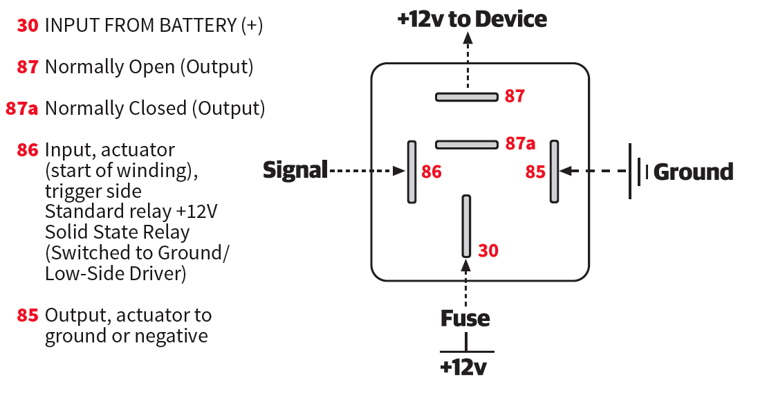
Relay terminology. The ISO mini relay we have looked at above has 4 pins (or terminals) on the body and is referred to as a make & break relay because there is one high current circuit and a contact that is either open or closed depending upon whether the relay is at rest or energised. If the contact is broken with the relay at rest then the relay is referred to as Normally Open (NO) and if ...

Current relay wiring diagram
55 - Power Factor Relay 56 - Field Application Relay 59 - Overvoltage Relay 60 - Voltage or Current Balance Relay 62 - Time-Delay Stopping or Opening Relay 63 - Pressure Switch 64 - Ground Detector Relay 65 - Governor 66 - Notching or jogging device 67 - AC Directional Overcurrent Relay 68 - Blocking or "out of step" Relay Relay Current Flow & Wiring DiagramsAmazon Printed Bookshttps://www.createspace.com/3623928Amazon Kindle Editionhttp://www.amazon.com/Automotive-Electronic-D... Overload Relay Wiring Diagram. Whenever the flow of current toward the motor is more than what the heaters are charged for, the overload explores later than some seconds. The classes of overload relay can be classified into three types based on the duration of relay explore.
Current relay wiring diagram. Relays allow a low current circuit to control one or more higher current circuits. Relays provide these benefits; 1. Thinner cables can be used to connect the control switch to the relay thereby saving weight, space and cost. 2. Relays allow power to be routed to a device over the shortest distance, thereby reducing voltage loss. 3. The wiring diagram for a potential relay is shown in ill 10.7. ... Motor current will increase if the potential relay does not drop the starting circuit at ... Jun 20, 2020 - 55 New Potential Relay Wiring Diagram- A govern relay is used in ... Danfoss Current Relay WiringCopeland Potential Relay Wiring Diagram Run ... -Possible to use for current scanning from current transformer.-Universal supply AC/DC 24 - 240 V.-Relay status is indicated by LED.-1-MODULE,DIN rail mounting. A1 A2
ELR Wiring diagram A typical wiring diagram of an earth leakage relay is shown below. Operational power is applied to the terminal A 1 and A 2 of the ELR and the CBCT is connected to the terminals T 1 and T 2. The normally closed terminals of the fault signalling contacts are connected to the Undervoltage release coil of the circuit breaker. J16 Current supply relay J519 Onboard supply control unit SC8 Fuse 8 on fuse holder C T6f 6-pin connector T73a 73-pin connector T73bA57 73-pin connectorPositive connection 3 (30), in dash panel wiring harness A104 Positive connection 2 (15), in dash panel wiring harness B318 Positive connection 4 (30a) in main wiring harness 3 Sep 2012 — If the relay does not have an L or M terminal, use the system's wiring diagram to properly identify its coil terminals. Jan 19, 2022 · 7.3 Powerstroke Glow Plug Relay Wiring Diagram. Meishuo Electric – China professional auto relay manufacturers and suppliers. 12+ Dual Electric Fan Relay Wiring Diagram Wiring G2sonline january 1 to march 31 2020 $69 95 $159 95 mercedes 300e owners manual by mmamakas issuu glow plug current rail seat ibiza st vwvortex 91 cabriolet engine partment […]
11 Pin Relay Base Schematic. Here are a number of highest rated 11 Pin Relay Base Schematic pictures upon internet. We identified it from honorable source. Its submitted by direction in the best field. We agree to this nice of 11 Pin Relay Base Schematic graphic could possibly be the most trending topic like we portion it in google benefit or ... How to read wiring diagrams 1 - Relay location number Indicates location on relay panel. 2- Arrow Indicates wiring circuit is continued on the previous and/or next page. 3 - Connection designation - relay control module on relay panel Shows the individual terminals in a multi-point connector. For example: contact 24 on terminal on relay panel. 4 - Diagram of threaded pin on relay panel Tim Smith from Hudson Valley Community College uses an interactive wiring diagram to discuss issues related to a current relay. Tim uses the interactive wiri... Ge Refrigerator Ptc Relay Replacement #wr07X10025 - Youtube - Refrigerator Start Relay Wiring Diagram. The diagram provides visual representation of an electrical structure. On the other hand, the diagram is a simplified version of the structure. This makes the process of assembling circuit easier.
Circuit diagram of the voltage divider, the control relays ...
The diagram above is the 5 pin relay wiring diagram. There are different kinds of relays for different purposes. It can be used for various switching. Relay can be the best option to control electrical devices automatically. 5 pin is compromised of 3 main pins and an SPDT (single pole double throw).

Remote control switch RF wireless 4 channel 433Mhz switch ...
MAGNETIC RELAYS. A current passing through a conductive wire covered with an insulated surface wrapped around an iron rod creates a magnetic field that draws nearby metals toward itself. Magnetic relays are manufactured using this feature. Magnetic relays are made up of three basic parts. These are relay bobbins, relay contacts and pallet.

A security guard walks around the Arc de Triomphe securing the parameters from the Gilet Jaune movement’s protest on December 8th.
A DC schematic diagram is frequently used to represent the logic of electrical control systems (switching or relaying) including a number of switches or contacts, time delay and latching type relays, push buttons, limit switches, lights, and controlled devices like motor starters and solenoid operated valves.
Alternating Current Electronic Relay Circuit - Remote ...
Refer to Setting Ranges and Wiring Connections on the I1, I2, and I3 current input terminals. 5. The K8DT-AS3 is designed to be used in combination with the OMRON K8AC-CT200L Current Transformer (CT). Wiring Example Directly Inputting a Current Using a CT Transistor Output Note: Use copper wires with a rating of 75°C or an equivalent rating ...

Series Resistance in a mA Trip Relay Test Circuit - CR4 ...
The current to be monitored (measured value) is applied to terminals B1/B2/B3-C. The supply voltage applied to terminals A1-A2 is displayed by the glowing green LED. If the measured value exceeds the adjusted threshold value, the output relay energizes and the red LED (overcurrent) and the yellow LED (relay energized) glow.
![[KS_1599] Current Relay Wiring Free Diagram](https://static-resources.imageservice.cloud/609323/making-sense-of-automatic-charging-relays-marine-how-to.png)
[KS_1599] Current Relay Wiring Free Diagram
Remove the screw from the bracket and place the common wire that will activate the relay between the bracket and the plastic case. 4. If the current through the common wire is less than 4 amps, wrap it one or more additional turns around the metal bracket. 5. Replace the metal screw in the bracket. 6. Complete the wiring as shown in the appropriate diagram. 7. Read the checkout procedure. 8.

HVAC Motor-start relays | HVAC Troubleshooting
Jul 04, 2018 · July 4, 2018 by faceitsalon. Assortment of current sensing relay wiring diagram you’ll be able to download free of charge. Please download these current sensing relay wiring diagram by using the download button, or right visit selected image, then use Save Image menu. Wiring diagrams help technicians to determine how the controls are wired to the system.

Image from page 202 of "Cyclopedia of applied electricity : a general reference work on direct-current generators and motors, storage batteries, electrochemistry, welding, electric wiring, meters, electric lighting, electric railways, power stations, swit
Weak Positive Output to High Current Positive Output Relay Wiring Diagram. Often it is necessary to provide more current than the positive output of an alarm or keyless entry can provide. When this is the case, use the following diagram. Relay Diagrams - Quick Reference (Last Updated: 5/4/2020) 1.

Image from page 71 of "Electric railway journal" (1908)
The pickup current is the current required to close the relay contacts. Dropout current is the current at which the contacts open. Standard maximum pickup and minimum dropout ratings are shown in the table. PICKUP AND DROPOUT RATINGS Klixon Rating Numbers Maximum Pick-up (Amperes) Minimum Drop-out (Amperes) 9660-077-078-079 1.01 1.06 1.12 0.86 0.91 .96-080
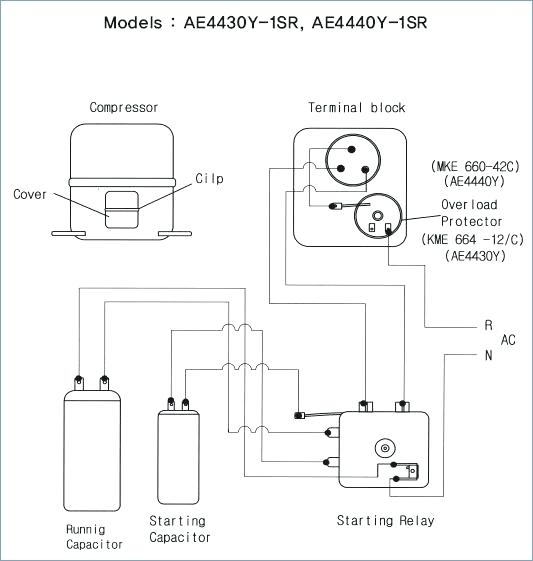
Compressor Current Relay Wiring Diagram
A-4 HOW TO READ THE WIRING DIAGRAMS - How to Read Circuit Diagrams HOW TO READ CIRCUIT DIAGRAMS The circuit of each system from fuse (or fusible link) to earth is shown. The power supply is shown at the top and the earth at the bottom to facilitate understanding of the current flow.

Ice Breaker: Troubleshooting Current Relays | 2012-09-03 ...
The most intelligent device. We developed Shelly 1 with an integrated WEB interface for device management and a secure OTA update. You can set your weekly schedules for On/Off without the need of any additional equipment. Shelly 1 knows your location, gives you high security and provides device access control.

Image from page 234 of "Official proceedings" (1901)
Standard ISO Relays We sell both 4 pin normally open (SPST) and 5 pin change-over (SPDT) relays with resistor protection in … DPDT Relay Wiring Diagram. 3 of the master sw termi

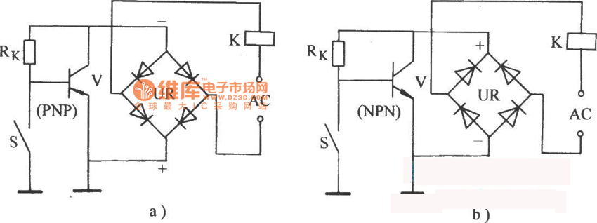
Current Relay Operation
A practical differential current protective relay system would monitor current through all six stator wires on the generator, comparing currents in and out of every phase: If the CT primary currents \(I_{C1p}\) and \(I_{C2p}\) are equal and the CT ratios are equal, the CT secondary currents \(I_{C1s}\) and \(I_{C2s}\) will be equal as well.
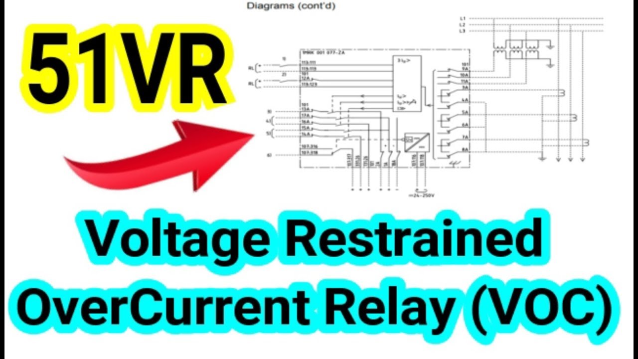
Voltage Restrained Over Current Relay 51VR operating ...
Jun 26, 2021 · Toyota Venza Interior Light Auto Cut Circuit Lighting System Service Manual. Autocut circuit diagram for ilizer auto cut relay switch dc understanding automotive relays over cur off power supply using interior light low voltage protection electric fuel pump rc24 rc36 pin starter interrupt diagrams type automatic 3 tested 220v high and hid wiring cbr forum gsic global service information center ...
Quick Tech | Automotive Relays - DSPORT Magazine
Overload Relay Wiring Diagram. Whenever the flow of current toward the motor is more than what the heaters are charged for, the overload explores later than some seconds. The classes of overload relay can be classified into three types based on the duration of relay explore.

47 Current Sensing Relay Wiring Diagram - Wiring Diagram ...
Relay Current Flow & Wiring DiagramsAmazon Printed Bookshttps://www.createspace.com/3623928Amazon Kindle Editionhttp://www.amazon.com/Automotive-Electronic-D...
![[DIAGRAM] Wiring Diagram Of Earth Fault Relay FULL Version ...](https://d2vlcm61l7u1fs.cloudfront.net/media%2F93a%2F93a303ae-494e-4a51-ad1b-79a5e615fb10%2FphpRzlJqn.png)
[DIAGRAM] Wiring Diagram Of Earth Fault Relay FULL Version ...
55 - Power Factor Relay 56 - Field Application Relay 59 - Overvoltage Relay 60 - Voltage or Current Balance Relay 62 - Time-Delay Stopping or Opening Relay 63 - Pressure Switch 64 - Ground Detector Relay 65 - Governor 66 - Notching or jogging device 67 - AC Directional Overcurrent Relay 68 - Blocking or "out of step" Relay

Potential Relays - What Happened to Terminal 3? - HVAC ...

Components for Electric Motors: 10.1 Starting Relays for ...
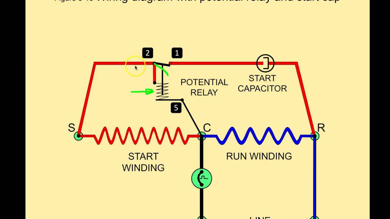
Potential Relays - Commercial Refrigeration Online HVAC ...

billboard urging protestors to go home
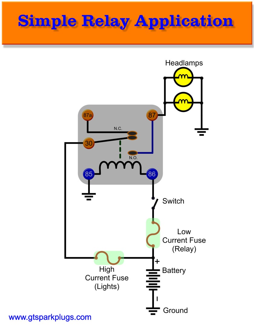
Introduction to Automotive Relays | GTSparkplugs

Electrical Control Circuit Schematic Diagram of Capacitor ...

Secondary injection tests for checking the correct ...
47 Current Sensing Relay Wiring Diagram - Wiring Diagram ...

How times were before COVID-19 hit the world 😷

Image from page 648 of "Popular science monthly" (1872)

How to Installation Control Current relay in three phase ...

Refrigerator Current Relay | Refrigerator Troubleshooting ...

Potential Starting Relays

47 Current Relay Wiring Diagram - Wiring Diagram Source Online

Generous Potential Relay Wiring Diagram Images - Wiring ...
47 Current Sensing Relay Wiring Diagram - Wiring Diagram ...

Supersized solar plus storage coming to California

George Floyd Protest

290 Current Relays
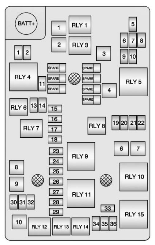
Chevrolet Sonic (2013 - 2016) - fuse box diagram - Auto Genius

Image from page 1200 of "Electric railway journal" (1908)
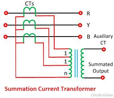
What is Summation Current Transformer? Definition & Types ...


Comments
Post a Comment