40 stirling engine pv diagram
A Stirling engine is a type of a heat engine that runs when a temperature difference is applied between the top and bottom plates of the engine body. In this... – Stirling Engine – Steam engine – Elastic engine. N S Scissor‐Lift ... Carnot Cycle PV Diagram Our heat engine is not exactly a Carnot cycle, however there are similarities between it and our HM diagram. Paramagnetism vs. Ferromagnetism • Materials are made up of magnetic domains, which ...
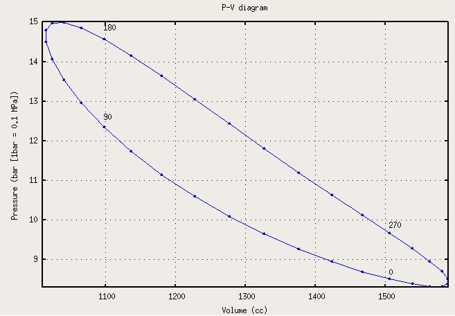
Many modificatons since the last video gave me the possibility to measure the PV diagram of the stirling cycle in real-time.I attached a pressure sensor to t...

Stirling engine pv diagram
4.11.2018 · Chevy Aveo Engine Diagram Wiring Diagram Library 2000 Chevy Silverado Grinding In Reverse Jump Seat Truck Engine F7d00 96 Gmc Sierra Engine Diagram Digital Resources General Motors Engine Guide Specs Info Gm Authority Vortec 8100 8 1l Wiring Harness Information 2004 ... The Stirling engine is an external combustion engine. This characteristic differentiates it from other types of engines such as the Otto engine or the diesel engine which are internal combustion engines. ... PV diagram of a real Stirling cycle; four angular positions of the crank of the machine running the cycle are indicated ... Stirling cycle is one ideal cycle for the operation of Stirling engine. First we will see here the PV and TS diagram for Stirling cycle, we will understand here the various processes involved and finally we will determine the thermal efficiency of the Stirling cycle.
Stirling engine pv diagram. The Stirling cycle is a thermodynamic cycle that describes the general class of Stirling devices. This includes the original Stirling engine that was invented, developed and patented in 1816 by Robert Stirling with help from his brother, an engineer.. The ideal Otto and Diesel cycles are not totally reversible because they involve heat transfer through a finite temperature difference during ... Let us now consider the four stages of the Stirling cycle. Let the engine cylinder contain m kg of air at its original position represented by point 1. At this point, let P1, T1, and V1 be the pressure, temperature, and volume of the air respectively.. Read also: Four-stroke Otto-cycle Spark-Ignition Engine with [P-v and T-s Diagram] Stages of an Ideal Stirling Cycle diagram, the clockwise and counterclockwise directions indicate power and heat pump cycles, respectively. Relationship to work Example of P-V diagram of a thermodynamic cycle. Because the net variation in state properties during a thermodynamic cycle is zero, it forms a closed loop on a PV diagram. A PV diagram's Y axis shows pressure (P) and X ... PV Diagram of a Real Stirling Engine Stirling PV diagram typical of a real engine. Note the rounded corners. Image courtesy Comsol. The moving parts of all high-speed machines need to have a smooth motion, or the machine will tear itself apart. High-speed engines of any type will have a PV diagram that looks round on the edges like this one
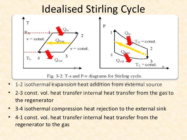
As we can see here from PV and TS diagram, there will be two reversible isothermal processes and two reversible constant volume processes. Process, 1-2: Isothermal expansion from state 1 to state 2. Heat energy will be added here from external source. Volume will be increased but pressure will be reduced during this process. ΔU = 0, Carnot's diagram. In the adjacent diagram, from Carnot's 1824 work, Reflections on the Motive Power of Fire, there are "two bodies A and B, kept each at a constant temperature, that of A being higher than that of B.These two bodies to which we can give, or from which we can remove the heat without causing their temperatures to vary, exercise the functions of two unlimited … PV diagram of a real Stirling cycle; four angular positions of the crank of the machine running the cycle are indicated. The real cycle can be represented in a pressure-volume diagram (PV) with a closed curve with a shape; this curve represents, with different values of pressure and temperature, most of the real Stirling cycles. Author: Oriol Planas - Industrial Technical Engineer, specialty ... The Stirling cycle (patented 1816) is a thermodynamic model, this time based exclusively on a gas state. Figure 14.3 presents in a P-V diagram an ideal cycle consisting of four steps, two isocoric (constant volume) heat exchange and two isothermal expansion/compression changes. Initially, the gas is compressed from P 4 to P 1 isothermally by removing the amount of heat Q C.
The pV diagram for an ideal Stirling cycle is shown in Fig (2). In our setup, two pistons move in the cylinder, shown schematically in Fig (3); the top region of the cylinder is heated by an electric heater and the lower walls of the cylinder are cooled by owing water. The volume of air is changed by the movement of the lower piston. The upper piston moves the air from the heated region of the ... Stirling cycle is a thermodynamic cycle upon which a Stirling Engine works. Stirling engine is a closed cycle regenerative heat engine. It works on either air or any other gas. Stirling cycle is invented by Robert Stirling with help from his brother (in 1816). Below are P-V and T-S Diagrams of the Stirling Cycle. Stirling engine is a closed cycle regenerative heat engine. It works on either air or any other gas. Stirling cycle is invented by Robert Stirling with help from his brother (in 1816). Below are P-V and T-S Diagrams of the Stirling Cycle. Stirling Cycle is comprised of four processes Process 1-2 It is isothermal heat addition process. simple method and very useful during Stirling engine development. This theory is based on the isothermal expansion and compression of an ideal gas. 2. ASSUMPTION OF SCHMIDT THEORY The performance of the engine can be calculated using a P-V diagram. The volume in the engine is easily calculated by using the internal geometry.

PPT - Thermodynamic Cycles PowerPoint Presentation - ID ...
12.5.2020 · The Rankine cycle is a modified form of Carnot cycle, in which the isothermal compression (3-4) is continued unit the steam is condensed into water. A Carnot cycle, using steam as a working substance, is represented or p-v and t-s diagram as shown in the figure.

PV Diagram of a Stirling Engine (STINE, 2001) | Download ...
which requires signi cant engineering to achieve high performance at low cost. The Stirling engine is the central component of the system and is the focus of this dissertation. Figure 1.1: System Diagram 1.2 Stirling Engine Background The Stirling engine is a heat engine that utilizes the Stirling Cycle to convert thermal energy
Stirling Engine Pv Diagram - Wiring Diagram
ideal Stirling cycle. P-V diagram Figure 2 shows the experimental setup used to simultane - ously measure the pressure and volume of the displacer-type Stirling engine. Pressure measurement — To monitor the pressure change of the gas in the Stirling engine, an inexpensive differential pressure sensor was pur - chased.
chapter 6
In these four forms of CSP generation technology, parabolic dish/Stirling engine power generation technology enjoys the highest concentration ratio (1000–3000), followed by solar tower (300–1000), whereas the line focusing system's parabolic trough (70–80) and linear Fresnel reflector (25–100) concentration ratios are comparatively low.

p-V diagram for the ideal process Stirling engine ...
Heat Engine PV Diagram. Heat engines can be typically illustrated on a PV diagram, Pressure-Volume (PV) diagrams are the basic tool for the study of heat engines that use gas as the working substance.PV diagram will be a closed-loop for a cyclic heat engine. The area of the loop is the representation of the amount of work done during the cycle.
32 Stirling Engine Pv Diagram - Wiring Diagram Database
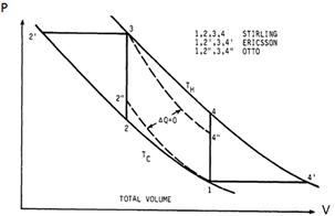
Now PV-diagram of the Stirling engine shown in Figure 2 can be examined in detail. The key points are that during expansion along path 1-2 there is no temperature difference so that the change in internal energy dU = 0. From the first law of thermodynamics heat added from the hot reservoir is the same as the work done by the system, Q H = W H.

Stirling Engine Pv Diagram - General Wiring Diagram
The p-v and t-s diagram of this cycle are shown in the figure. Let us now consider the four stages of the Stirling cycle. Let the engine cylinder contain m kg of air at its original position represented by point 1. At this point, let P1, T1, and V1 be the pressure, temperature, and volume of the air respectively.

PV and Ts diagram of Stirling engine cycle. | Download ...
A Stirling engine is a type of a heat engine that runs when a temperature difference is applied between the top and bottom plates of the engine body. In thi...
General discussion of Stirling Engine part 3
This video describes and demonstrates the real-time measurement of a Stirling engine's pressure versus volume diagram. Kontax Stirling Engines: https://www.s...

Stirling Engine Pv Diagram - Wiring Diagram
A Stirling engine is a heat engine that is operated by the cyclic compression and expansion of air or other gas (the working fluid) at different temperatures, resulting in a net conversion of heat energy to mechanical work. More specifically, the Stirling engine is a closed-cycle regenerative heat engine with a permanent gaseous working fluid. Closed-cycle, in this context, means a ...
35 Stirling Engine Pv Diagram - Free Wiring Diagram Source
Here are a number of highest rated Stirling Engine Pv Diagram pictures on internet. We identified it from well-behaved source. Its submitted by processing in the best field. We acknowledge this kind of Stirling Engine Pv Diagram graphic could possibly be the most trending subject subsequently we ration it in google benefit or facebook.
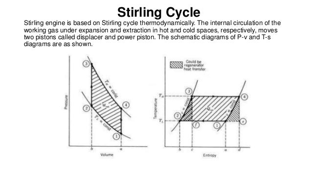
Stirling Cycle
If the engine is driven by a motor, and the process curves in the T-s and P-v diagrams run counter clockwise, the Stirling cycle operates as a refrigerator and/or heat pump. The coefficient of performance for Stirling cycle is: H L H HP H L L f T T T COP T T T COP Re Note that the COP's of the Stirling cycle are the same as the Carnot cycle.

Stirling Engine Pv Diagram - Diagram Resource Gallery
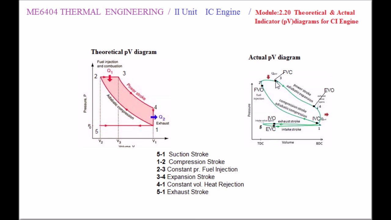
28.11.2021 · The fig shows the valve timing diagram for a four-stroke diesel cycle engine. Inlet valve opens 10° to 25° in advance of the top dead centre and closes 25° to 50° after the bottom dead centre. the exhaust valve opens 30 ° to 50° in advance of the bottom dead centre and closes 10° to 15° after the top dead centre.
Heat Engines
became more popular. The Stirling engine continues to attract attention, periodically, as a more fuel e cient and potentially cleaner engine for some applications. Currently, the primary application of Stirling cycles is in refrigeration. The Stirling Cycle The pV diagram for an ideal Stirling cycle is shown in Fig (2). In our setup, two pistons

Stirling Engine Diagram - Fuse & Wiring Diagram
A Stirling engine is a specific flavor of heat engine formulated by Robert Stirling in 1816; this means it can transform the flow of heat into mechanical work (such as spinning a crankshaft). The key term is "flow of heat"; there must be two "reservoirs" that are separated, and these reservoirs must be at different temperatures in order ...

Stirling Engine Pv Diagram - General Wiring Diagram
This video describes and demonstrates the real-time measurement of a Stirling engine's pressure versus volume diagram. Kontax Stirling Engines: https://www.s...

Carnot vs Stirling (9/15/2014)
In the pV diagram (Fig.3) the corresponding cycle consists of two isotherms and two isochores. The volume V is the volume between the two pistons. In practice the cycle is not divided in discrete steps as described above. ... Stirling engine (Stirling cryocooler)
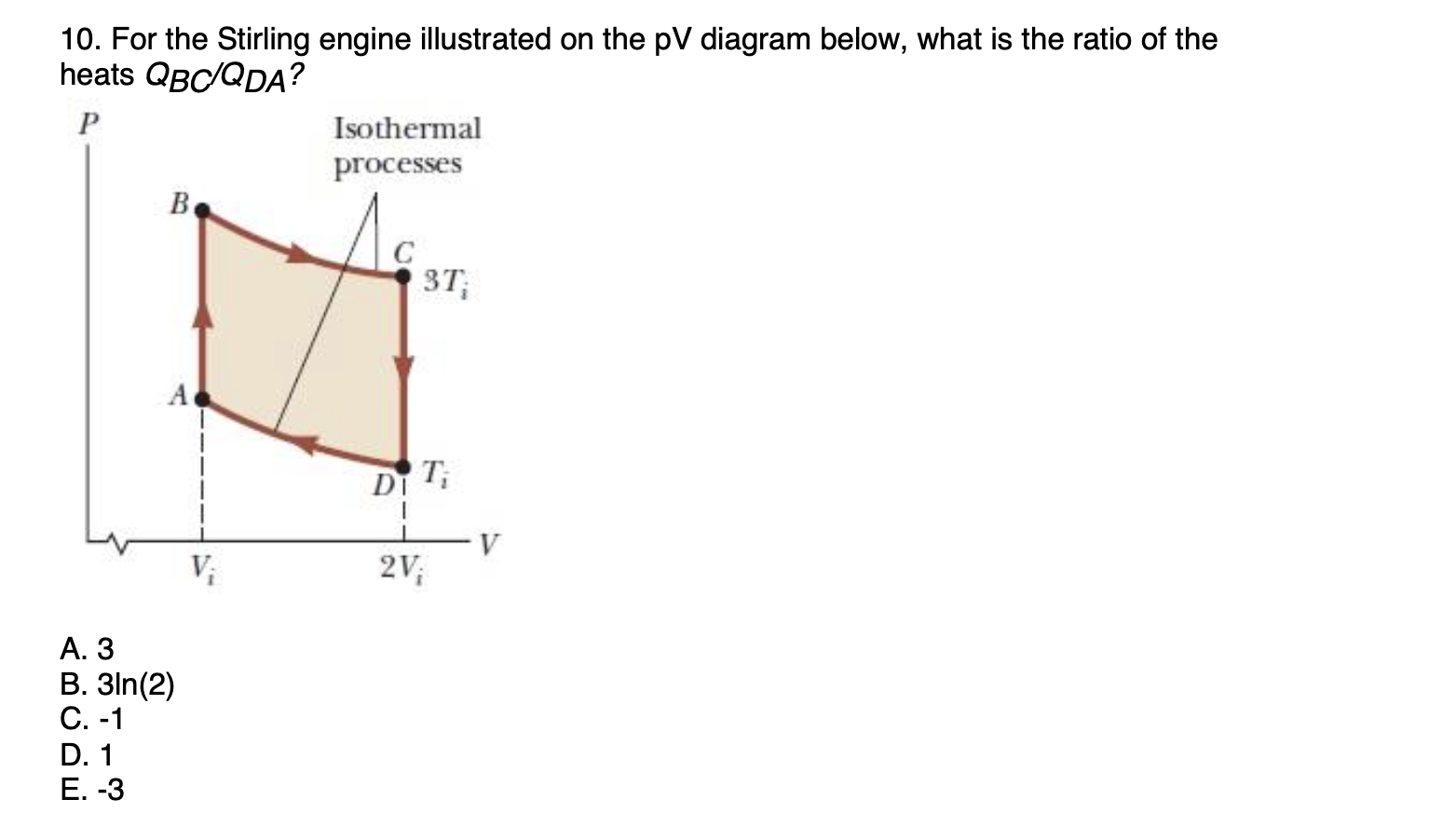
Answered: 10. For the Stirling engine illustrated… | bartleby
The Stirling engine car operates with Stirling cycle. There were basic two graphs for Stirling engine such as P-V diagram and T-S diagram shows in Figure 4. By referring this diagrams can...

Stirling Engine Diagram
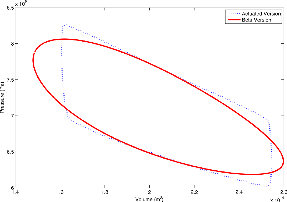
The PV diagram of α-Stirling engine, Figure 1, is far away from an ideal PV dia-gram Figure 2. The principle schema of the α-Stirling engine is shown in Figure 3.
35 Stirling Engine Pv Diagram - Free Wiring Diagram Source
Stirling cycle is one ideal cycle for the operation of Stirling engine. First we will see here the PV and TS diagram for Stirling cycle, we will understand here the various processes involved and finally we will determine the thermal efficiency of the Stirling cycle.
Stirling Engine Pv Diagram - General Wiring Diagram
The Stirling engine is an external combustion engine. This characteristic differentiates it from other types of engines such as the Otto engine or the diesel engine which are internal combustion engines. ... PV diagram of a real Stirling cycle; four angular positions of the crank of the machine running the cycle are indicated ...

Stirling Engine Pv Diagram - General Wiring Diagram
4.11.2018 · Chevy Aveo Engine Diagram Wiring Diagram Library 2000 Chevy Silverado Grinding In Reverse Jump Seat Truck Engine F7d00 96 Gmc Sierra Engine Diagram Digital Resources General Motors Engine Guide Specs Info Gm Authority Vortec 8100 8 1l Wiring Harness Information 2004 ...

PV Diagram of a Stirling Cycle (STINE, 2001) | Download ...

(PDF) 1D modelling of an alpha type Stirling engine

35 Stirling Engine Pv Diagram - Free Wiring Diagram Source

(PDF) A Theoretical Improvement of a Stirling Engine PV ...

Sunset Afterglow

Thermodynamic Stirling cycle: a) P-V diagram, b) T-S ...
Public Science Framework-Journals - Paper - HTML

Stirling Engine Diagram

UNIVERSITY OF NEW HAVEN STIRLING ENGINE PROJECT MECHANICAL ...
Power and Cooling Systems - Cytherion Solutions

P-V and T-S diagrams of the Ideal Stirling Cycle ...

Chapter 3b - The First Law - Closed Systems - Stirling ...
Engine Pv Diagram - Wiring Diagram & Schemas
Stirling technológia: Béta stirling (alaptÃpus)

Google in Sunnyvale, CA, at West Java Drive.

(PDF) VALIDATION OF THE DIRECT METHOD FOR STIRLING ENGINE ...
Heat Engines
Stirling cycle & its applications


Comments
Post a Comment