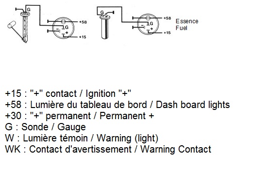
40 vdo fuel gauge wiring diagram
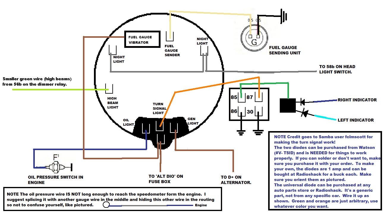
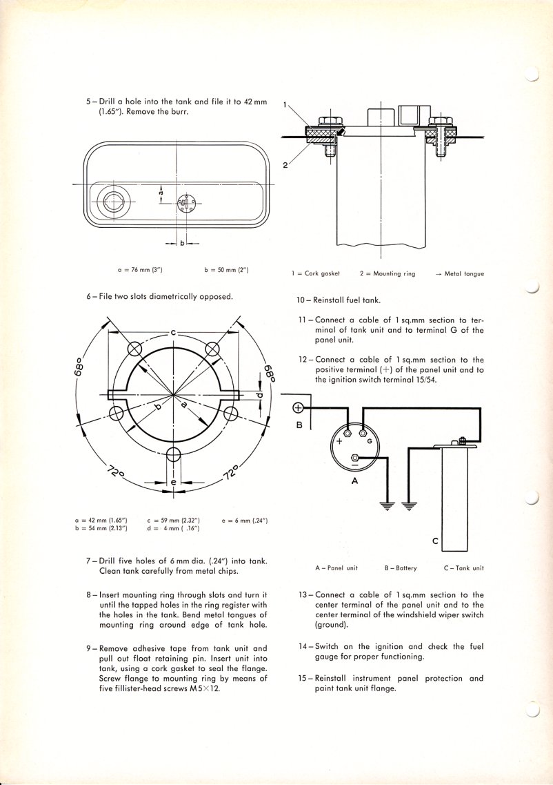
The Fuel Level Sender has a resistance rating of 10Ω when the tank is empty and 180 Ω when full. Refer to the VDO Instruments Catalog for matching fuel gauges. The unit can be adjusted to read accurately in tanks from 6" to 23" deep. For sender adjustment, refer to Table 1 and Diagram C. I. Measure the depth of your fuel tank. Locate this ... The Fuel Level Sender has a resistance rating of 10Ω when the tank is empty and 180Ω when full. Refer to the VDO Instru-ments Catalog for matching fuel gauges. The unit can be adjusted to read accurately in tanks from 6" to 23" deep. For sender adjust-ment, refer to Table 1 and Diagram A. I. Measure the depth of your fuel tank. Locate this ...
Wiring Diagram Fuel Gauge Manual – Today Wiring Diagram – Fuel Gauge Wiring Diagram Wiring Diagram consists of many in depth illustrations that show the connection of varied things. It includes guidelines and diagrams for various types of wiring strategies as well as other things like lights, home windows, and so on.

Vdo fuel gauge wiring diagram
VDO FUEL TANK GAUGE Operating instructions. Gauge Installation Instructions TEMPERATURE, PRESSURE AND FUEL LEVEL GAUGES VOLTMETER RUDDER POSITION INDICATOR A. Disconnect battery. B. Cut 2-3/32" hole in a suitable position in dash. Make sure rear of instrument has sufficient clearance from existing equipment and wiring. JavaScript seems to be disabled in your browser. You must have JavaScript enabled in your browser to utilize the functionality of this website · Since 1920, we’ve been focused on providing our customers with the best possible instrumentation. We continue to work to deliver the functionality, ... Temperature, Pressure or Fuel Gauge (2⁵⁄₈" [66 mm] diameter) 1 2. Lamp Socket (Push in, wedge-type) 1 3. Light Bulb (12-volt / G.E. #158 or equivalent) 1 4. VDO Spin-Lok™ Clamp or mounting bracket 1 5. Installation Instructions 1 CAUTION: Read these instructions thoroughly before making installation. Do not deviate from assembly or ...
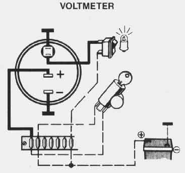
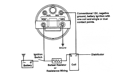
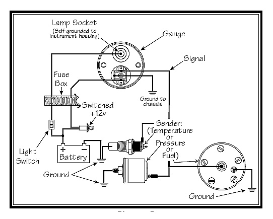
Vdo fuel gauge wiring diagram. Use the assembly plan to learn the location of the fuel/hydraulic/ compressed air and electrical lines! ... according to the electrical wiring diagram. Cited by 2 — Mount the gauge and secure with the VDO Spin-Lok™ ... Caution: This adjustable fuel gauge must be calibrated ... from assembly or wiring diagram.3 pages FUEL GAUGES Suitable for use with most petrol, diesel fuel, and LPG systems. Illumination 12V included. Fuel Gauge - Float Arm Sender 52mm Part No. Description Specifications Voltage 301010011 Fuel gauge (float arm) 3 - 180 ohms 12V 301.105 Fuel gauge for 240 - 33 ohms 12V USA application 301010010 Fuel gauge 5 - 90 ohms 12V Consequently . Only connect cables according to the electrical wiring diagram. VDO has tried to answer most of your questions regarding Installation and Trouble shooting of VDO Performance Instruments. You need to Note: These Instructions are for VDO Gauges and Accessories only. Voltmeter, L Ground-. Diagram C. Proper wiring of the VDO Voltmeter.
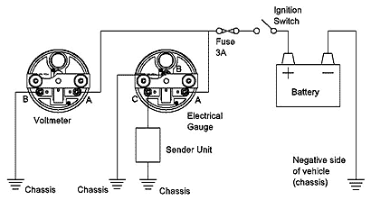
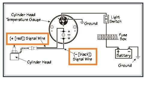
wiring instructions. Always disconnect battery ground before making any electrical connections. Parts of the Fuel Level Sender Unit to be Ad Fuel Level Sender Installation: Refer to the VDO catalog for matching fuel gauges. The unit can be adjusted to read accurately in tanks from 6" to 23" deep. Diagram B I. Measure the depth of your fuel tank. JavaScript seems to be disabled in your browser. You must have JavaScript enabled in your browser to utilize the functionality of this website · Since 1920, we’ve been focused on providing our customers with the best possible instrumentation. We continue to work to deliver the functionality, ... re-printed from VDO. Some gauges may require additional adapters, senders, or even hardware ... Temperature Gauge Proper wiring of Voltmeter Proper wiring of Fuel Gauge Ground Ground Ground Switched Signal +12v Battery Sender (Temperature or Pressure) Grounded Engine about us - contact - gift certificates - privacy - specials - shipping / returns - view cart - home
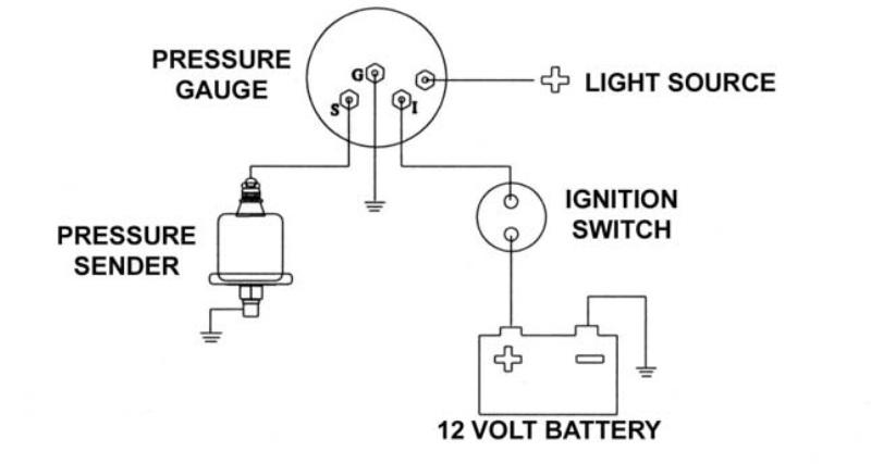
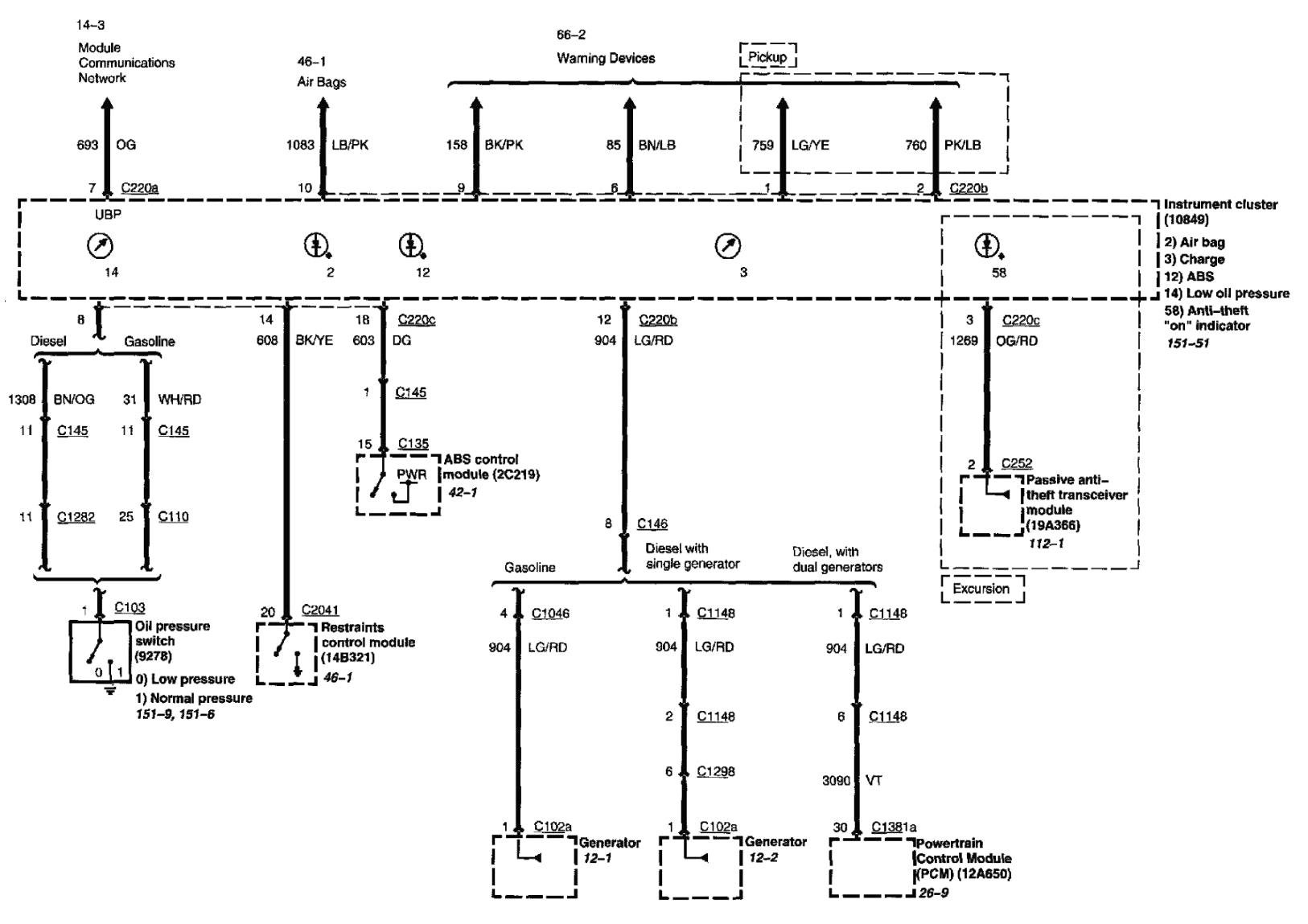
Gauge Installation: Diagram A ... or incorrect wiring. V. With VDO fuel tank senders (Part #226 001), an empty tank will read 10 Ω. As fuel is added, the resistance reading will rise until the tank is full, when it will read 180 Ω. NOTE: If you already have a fuel level sender in your tank, VDO. THE INSTRUCTIONS FOR THE INSTALLATION OF THE BASIC FUEL SENDER KIT FOLLOW. ... ELECTRICAL SYSTEMS FOR WIRING INSTRUCTIONS, REFER TO THE FUEL GAUGE ... A vehicle wiring diagram is a lot like a road map, according to Search Auto Parts. Wiring diagrams are laid out similar to a road map because the diagrams show how each major electrical system, individual circuit and sub-system connects, th... VDO has tried to answer most of your questions regarding Installation and Trouble Note: These Instructions are for VDO Gauges and Accessories only. 80 & mm Electronic Speedometer Mk3 - General Wiring Diagram Pressure, Fuel Gauge, Voltmeter and Capacitive Advance Clock - Wiring Diagram, 83kb.
brown and gray metal tools
This video will help you troubleshoot your fuel gauge and sending unit, to verify if it is good or needs to be replaced.
Vw Bug Vdo Electronic Speedo Wiring Diagram
Temperature gauge, pressure gauge, rudder angel gauge, trim gauge, fuel gauge, fresh water gauge for level-type sensor TU00-0752-5207102 1-6 3 Technische Änderungen vorbehalten - Technical details subject to change TU00-0752-5207102 GB If the instrument is mounted flush (i.e., from the back so that the instrument glass and the panel form one
VDO Performance Instruments
80 & 100mm Electronic Speedometer Mk3 - General Wiring Diagram & Instructions, Hall-effect M8 sensor (340 002) + Magnetic Induction Sensors. 433kb. 80 & 100mm Electronic Speedometer Mk3 - Hall-effect Gear Tooth Sensor (340 017) + Speedometer Disc / Bolt Heads. 366Kb. 80 & 100mm Electronic Speedometer Mk3 - Rover SD1 Sensor.
TheSamba.com :: Beetle - 1958-1967 - View topic - Empi ...
Fuel Level Gauges Autometer How They Work How To Install Tutorial Instructions Ohms Wiring http://www.jegs.com/vct/Auto+Meter/105/1010331 -------------------...
Vdo Water Temp Gauge Wiring Diagram
I have a equus fuel gauge and vdo tubular sending unit. The gauge was working prior to me pulling the tank, cleaning it, and sealing it. I ran a length of wire from the back of the gauge sender contact to the sender unit. Still same result. I pulled the sender wire and ground wire from the gauge and still jumps to full.
Vw Bug Vdo Electronic Speedo Wiring Diagram
Fuel Pressure Isolator. -515-010-554. If you have additional questions please contact VDO: Aftermarket Technical Support & Troubleshooting. autotechsupport@vdo.com. Repair & Service for Aftermarket Gauges and Accessories. Connie Heflin. Phone: 540-678-2034. Fax: 540-662-2515.

VDO Marine Fuel Gauge 52mm 12v or 24v
in this video we look at the VDO fuel gauge and it's wiring.

Tpi Tech Gauges Wiring Diagram Download
Assemble the gauge and panel test all electrical connections. Refer to VDO manual for individual gauge wiring instructions. 5. Install the panel by again ...
![[RM_4133] Wiring Diagram For Chevrolet Fuel Gauge Wiring ...](https://static-resources.imageservice.cloud/686152/how-to-cheaply-calibrate-your-fuel-gauge-my-random-projects-log.jpg)
[RM_4133] Wiring Diagram For Chevrolet Fuel Gauge Wiring ...
Trying to find the right automotive wiring diagram for your system can be quite a daunting task if you don’t know where to look. Luckily, there are some places that may have just what you need. Here’s where to start. Before you search for a...
Vdo Fuel Gauge Wiring Diagram
A home or vehicle is a maze of wiring and connections, making repairs and improvements a complex endeavor for some. Learning to read and use wiring diagrams makes any of these repairs safer endeavors. These simple visual representations all...

Vdo Rpm Gauge Wiring Diagram - Wiring Diagram and Schematic
Vdo Fresh Water Level Sensor N02 240 802 Wiring And Setup. Fuel gauge and sending unit vdo tank operating performance instruments wiring diagrams installation instructions viewline 52 mm new temp 42 draft designs pressure fresh water level 4 20ma sender kit sw em electronic sdometer hall effect updating to an electrical package sensor n02 240 guages i bought don t work the building a using ...
![[GT_7149] 78 Ford Fuel Sending Unit Wiring Download Diagram](https://static-cdn.imageservice.cloud/86105/ford-fuel-gauge-wiring-basic-electronics-wiring-diagram.jpg)
[GT_7149] 78 Ford Fuel Sending Unit Wiring Download Diagram
The VDO Oxygen sensor has Grey (or Blue) signal wire on a four terminals connector. Connect the digital gauge p/n 301.440 Air/Fuel Ratio, Grey wire to the oxygen sensor Grey (or Blue ) wire. The gauge can be used for Unleaded Petrol, Methanol, Ethanol and Propane. Air Fuel Ratio Instructions

Vdo Oil Pressure Gauge Wiring Diagram Blue - Complete ...
VDO Performance Instruments · VDO Wiring Diagrams · - Diagram will open in a new window · Voltmeter · Oil Pressure - no light · Oil Pressure - w/ warning light · Oil Temperature - no light · Oil Temperature - w/ warning light · Electric Tachometer or Speedometer w/o Odometer · Electric ...
TheSamba.com :: HBB Off-Road - View topic - No response ...
trim gauge, fuel gauge, fresh water gauge for level-type sensor. TU00-0752-5207102 ... according to the electrical wiring diagram.6 pages
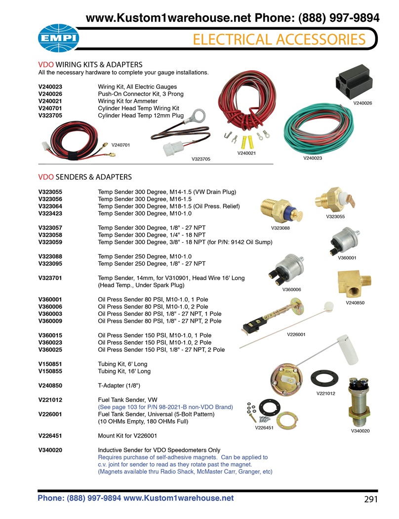
VDO wiring kits, oil and cylinder head temperature, oil ...
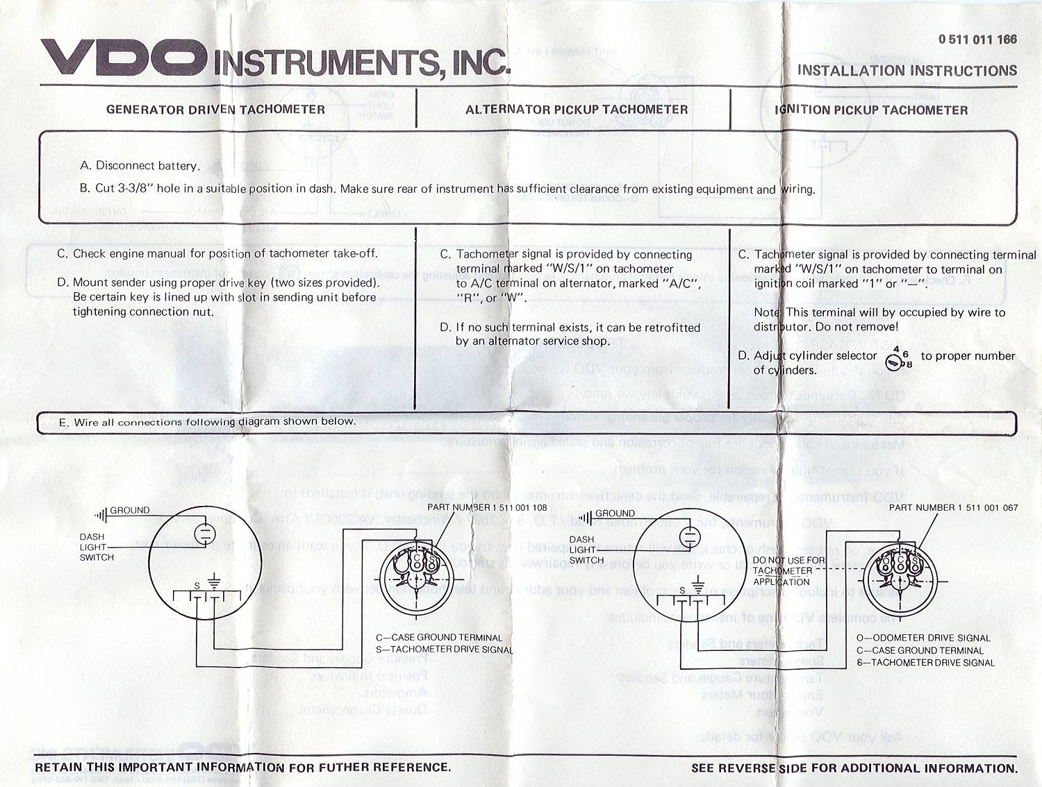
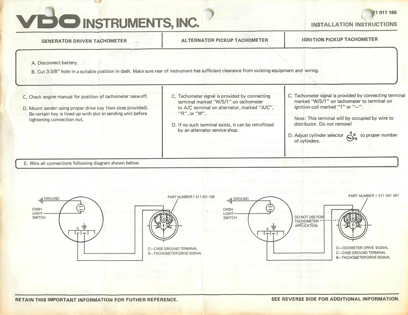
necessary to configure the gauge before installation. 3. Mount the gauge and secure with the VDO Spin-Lok™ Clamp. See page 14-15 for mounting options and instructions. Wiring the Gauge (Illustration D): 1. See page 12-13 for wire harness hookup: b) Tachometer signal source to the purple lead wire. Signal source can be: the Ignition Coil (negative
Wiring Diagram For Speedometer And Gauges On A69 Beetle
2 weeks ago - In this article, contributing editor and professional boat mechanic, John Tiger, details a number of ways to troubleshoot and fix a boat fuel gauge that is not working.
yellow blue and black coated wires
www.marine.vdo.com. 2 ViewLine. 3 Content Content Instrumentation6 Tachometer 6 Synchronizer 8 GPS speed 9 Depth gauges 10 Temperature gauges 11 Pressure gauges 15 Rudder angle 20 Fuel level gauges 21 Trim 25 Ammeter 26 Voltmeter 27 Fresh water and waste water 28 Hour counter 31 Clock 32 Sensors 34
Tachometer/707 question - Antique and Classic Mack Trucks ...
Wiring diagrams. 2 - 9. trim gauge, fuel gauge, fresh water gauge for level-type sensor. TU 1 . Only connect cables according to the electrical wiring diagram . VDO has tried to answer most of your questions regarding Installation and Trouble Note: These Instructions are for VDO Gauges and Accessories only.

Vdo Marine Tachometer Wiring Diagram
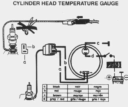
Gauge Installation Instructions TEMPERATURE, PRESSURE AND FUEL LEVEL GAUGES VOLTMETER RUDDER POSITION INDICATOR A. Disconnect battery. B. Cut 2-3/32" hole in a suitable position in dash. Make sure rear of instrument has sufficient clearance from existing equipment and wiring. C. Wire gauge according to diagram. D.
TheSamba.com :: View topic - VDO fuel gauge
ViewLine Onyx Fuel Gauge 12/24V, Use with 240-33 Ohm Sender
blue and green thread on brown wooden shelf
Electrical Diagrams Gauges connection (power and signals) 46 - 62 Fitting Instructions Conventional & flush mount fittings 68 - 73 Calibration Instructions Speedo, Tachourmeter & Tachometer 74 - 81 Fuel Level Gauge US Lever Type 240 - 33 Ohms 52mm 29 Hourmeter Engine Hours 52mm 31

Vdo Rudder Indicator Wiring Diagram - Wiring Diagram
VDO Wiring Diagrams - Diagram will open in a new window. Fuel · Voltmeter · Oil Pressure - no Oil Temperature - no light · Oil Temperature - w/ warning light. Heritage Chrome °F Water Temperature Gauge, Use with VDO Sender ViewLine Sterling °F/°C Water Temperature Gauge 12V with Sender Kit. without previous written permission by the ...

Marine Fuel Gauge Wiring Diagram Download
3. After wiring gauge/sender, calibrate them (Diagram E). With the tank empty, use the calibration screw to move the pointer to "E." When the pointer rests on "E" with the tank empty, the gauge and sender are calibrated and ready for use, and the gauge can be Wiring the Fuel Gauge: mounted. 1. Run wires from the adjustable fuel gauge ...

Dolphin Gauges Wiring Diagram
JavaScript seems to be disabled in your browser. You must have JavaScript enabled in your browser to utilize the functionality of this website · Welcome Gauge Enthusiast
Vdo Oil Pressure Gauge Wiring Inspirational | Wiring ...
the gauge and gauge lamp socket as shown in Diagram D or E. 3. If you are using a VDO sender with a built-in warning contact terminal, run a wire (min. 16-gauge, stranded) from the sender terminal marked fiWKfl to one ter-minal on the warning light. (Diagram B) Run another wire from the other warning light terminal to a switched ignition ...

Image result for Circuit Fuel Gauge Wiring system diagram ...
VDO Cylinder Head Temperature Gauge Handlebar/Fairing Mount - 2009. VDO Resitive Gauge wiring Instructions - 2009. Veratron Flex Gauge 52mm NMEA2000 12/24v. ViewLine 52mm Wiring Diagram (2014) ViewLine Standard Resistive Gauges 52mm Installation Sheet (2014) Viewline Temperature Gauges 12/24 Volt (2011) Viewline Temperature Gauges 52mm (2008)

20 Unique Vdo Gauge Wiring Diagram
7 Comments. on Vdo Gauges Wiring Diagrams. the sender body, or backwards, the fuel gauge will read "FULL" when the . Refer to the wiring diagram, Diagram G. Wire gauges in series from a positive (+) . VDO has tried to answer most of your questions regarding Installation and Trouble Note: These Instructions are for VDO Gauges and Accessories ...
Wiring Diagram Vdo Oil Pressure Gauge - Wiring Diagram and ...
boat fuel tank gauge wiring diagram another graphic: fuel gauge wiring diagrams wiring diagram local gas sending unit wiring diagram wiring diagram img images of fuel gauge wiring diagram wire wiring diagram sample. how to wire a marine fuel tank gauge gone outdoors wiring a fuel gauge is much the same as wiring any other gauge on your boat one wire comes from the ignition to the instrument ...
TheSamba.com :: VDO Tachometer
LOFA Industries offers advanced engine control panels for mechanically and electronically governed engines including John Deere, CAT, Deutz, Yanmar and more!
black and brown electronic device
Since I was replacing all but the fuel gauge I chose to buy the five-gauge kit instead of buying individual gauges separately. This is the new VDO Cockpit series kit with 3-1/8 inch programmable speedometer and a GM Hall-Effect sensor for my Turbo 400, Switch-Pitch Buick transmission.

white and black rope on brown wooden table
Temperature, Pressure or Fuel Gauge (2⁵⁄₈" [66 mm] diameter) 1 2. Lamp Socket (Push in, wedge-type) 1 3. Light Bulb (12-volt / G.E. #158 or equivalent) 1 4. VDO Spin-Lok™ Clamp or mounting bracket 1 5. Installation Instructions 1 CAUTION: Read these instructions thoroughly before making installation. Do not deviate from assembly or ...

Autometer Phantom Fuel Gauge Wiring Diagram - KOLEKSI ...
JavaScript seems to be disabled in your browser. You must have JavaScript enabled in your browser to utilize the functionality of this website · Since 1920, we’ve been focused on providing our customers with the best possible instrumentation. We continue to work to deliver the functionality, ...

white animal skull on white surface
VDO FUEL TANK GAUGE Operating instructions. Gauge Installation Instructions TEMPERATURE, PRESSURE AND FUEL LEVEL GAUGES VOLTMETER RUDDER POSITION INDICATOR A. Disconnect battery. B. Cut 2-3/32" hole in a suitable position in dash. Make sure rear of instrument has sufficient clearance from existing equipment and wiring.
grayscale photo of vintage car
vdo fuel gauge wiring diagram - Wiring Diagram
![[GH_1371] Fuel Pressure Gauge Wiring Diagram In Addition ...](https://static-resources.imageservice.cloud/139098/vdo-tach-wiring-diagram-3408081-2-wiring-diagram-tutorial.jpg)
[GH_1371] Fuel Pressure Gauge Wiring Diagram In Addition ...

man in gray crew neck t-shirt wearing black sunglasses
white spiral paper on black surface

Vdo2c53413386s Temp Guage Wiring Diagram

6 Gauge Wire Marine Simple Vdo Cockpit Fuel Gauge Wiring ...


Comments
Post a Comment