41 trailer breakaway switch wiring diagram
Trailer Breakaway Switch Wiring Diagram. By | April 20, 2012. 0 Comment. Breakaway kit installation for single and dual brake axle trailers etrailer com the trailer how to use it mechanical elements replacing switch on a with esco system wiring brakes fiberglass rv wire break away hopkins ener new 2 car mate inc electric control towing test ... There is a really fundamental Trailer Breakaway Switch Wiring Diagram. It's the 4-pin connector. This kind of connector is ideal for consumer trailers. It should not be carrying heavy loads throughout the trip. In addition to being light, it's advised that the connector doesn't have any power-draining accessory.
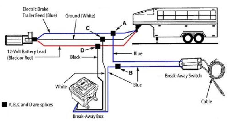
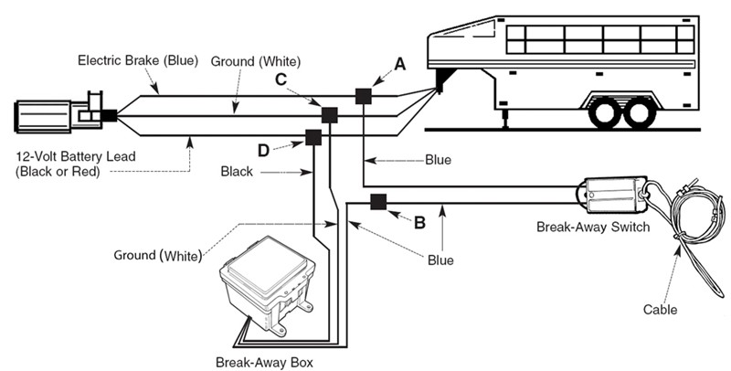
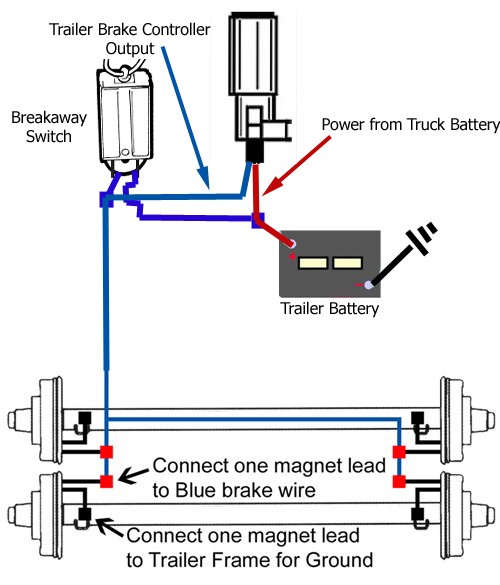
1. Splice one blue wire of the Break-Away Switch to the electric brake wire coming from the trailer side connector (A - see diagram on next page). 2. Connect other blue wire of Break-Away Switch to the blue wire (labeled "Brake") from the Break-Away box (B). (Note: Blue wires are interchangeable on the Break-Away Switch.) 3.

Trailer breakaway switch wiring diagram
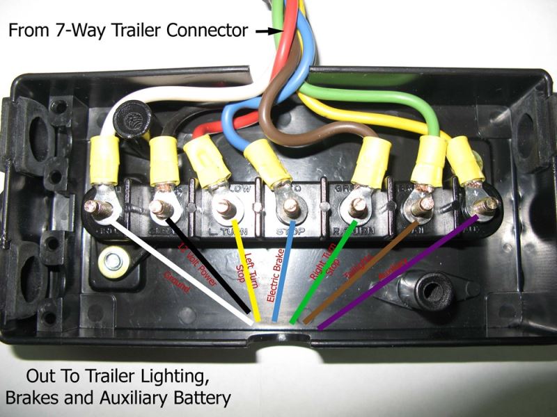
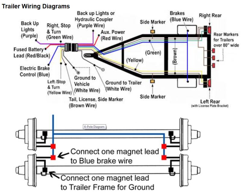
This Trailer Wiring Diagram With Breakaway Switch version is much more suitable for sophisticated trailers and RVs. It can transfer electricity better compared to the connector is suggested for higher-level electric in the car. Here is the diagram for 7-pin connector. White Pin for the floor. Page 198: Trailer Wiring General Machine Schematics Mobile Generator 23.2 Trailer Wiring Standard and Hydraulic Brakes Electric Brakes Br W – Br W Br W w c _ g r 0 0 0 5 2 2 wc_gr000523... Page 199: Trailer Wiring Components breakaway switch black cable brown white blue ground 7 way, 6way or 4 way plug c b pj trailers - utility trailer wiring diagram. 7 way plug vehicle running lights (brown) + auxilary right turn/ stop green backup lights electric brakes (blk/blue) trailer - ground (white) left turn 1 stop (yellow) 6 way plug vehicle electric brakes running lights ...
Trailer breakaway switch wiring diagram. October 8, 2021 · Wiring Diagram. by Trafalgar D. Law. How To Wire 7 Pole Trailer With Breakaway Switch Diagram - Wiring Diagram is the visual representation of a complicated electric circuit. It is extremely simple to draw a wiring diagram; you simply need to have a excellent comprehension on various kinds of wiring and their objectives. Wiring diagram for tandem axle trailer best breakaway kit. Splice one blue wire of the break away switch to the electric brake wire coming from the trailer side connector a see diagram on next page. The trailer wiring diagram shows this wire going to all the lights and brakes. Blue wires are interchangeable on the break away switch 3. Breakaway Systems & Battery Monitors; ... Wiring Harness with Auto Close - Suit Tecno/Nuova Mapa Step ... Electric Step Main Switch Only (006510) $41.95. View. On this page (typically below the product links) there is a helpful link section that will have the install instructions fo the Hopkins Breakaway kit part # 20400 that you referenced. I also attached an install video that shows the kit installed as well as a diagram for trailer breakaway wiring as well. The white wire is the ground wire.
Trailer Wiring Diagrams Trailer Wiring Connectors Various connectors are available from four to seven pins that allow for the transfer of power for the lighting as well as auxiliary functions such as an electric trailer brake controller, backup lights, or a 12V power supply for a winch or interior trailer lights. In this video, I replace my old worn looking trailer breakaway safety switch with a new one. I explain the wiring and test it.The breakaway switch is there i... 4. WARNING Disconnect trailer plug before testing breakaway unit. Failure to do so will result in severe damage to electronic brake control. 5. WARNING Check your breakaway system periodically to insure that wiring and connections are secure. A short or an open circuit can result in a no-brake condition. 6. For optimal performance, it is recom ... WIRING DIAGRAM. Step 1 - Mounting. Position the breakaway switch on the tongue of the trailer so that it allows the cable to reach the tow vehicle's trailer ...2 pages
Trailer Breakaway Switch Wiring Diagram - 3 wire trailer breakaway switch wiring diagram, rv trailer breakaway switch wiring diagram, trailer brake switch wiring diagram, Every electric arrangement is made up of various different components. Each component should be set and connected with other parts in specific way. Otherwise, the arrangement will not function as it should be. 2 Wire Trailer Breakaway Switch Wiring Diagram. 2 wire trailer breakaway switch wiring diagram. Splice the blue wire of the Break-Away Switch to the electric brake wire coming from the trailer side connector 2. The difference is that the 3-wire switch has a dedicated ground wire while the 2-wire switch grounds through its mounting hardware. Jul 11, 2019 · 100 amp manual transfer switch wiring diagram; 100 amp service panel wiring diagram; 1000 watts power amplifier schematic diagram; 11 pin relay wiring diagram; 110v plug wiring diagram uk; 12 pin trailer socket wiring diagram; 12v 2 prong toggle switch wiring diagram; 12v 3 way toggle switch wiring diagram; 12v led strip light wiring diagram Rewiring a trailer involves removing the old wiring and trailer lights, routing the new wiring harness through the trailer frame, installing new trailer lights and testing the lights. This guide walks through the steps required for how to rewire trailer lights. It can be used for how to rewire a utility trailer, boat trailer and others.
Trailer Breakaway Switch Wiring Diagram - Wiring Diagram And Schematic Diagram Images
Breakaway kit installation for single the trailer and how to hoppy break away wiring diagram full travel switch cheap electric brake control rv trailers wire on hopkins from umbilical rear safety sentry electronic connector brakes bs48 a 2 led with 7 neo manual controller replacement parts tank packaged sku 52011 system caravan works rh services.

person showing purple grapes
Bargman Breakaway Switch Wiring Diagram Splice one of the two wires coming out of the breakaway switch into the trailer brake The following diagram shows a typical wiring configuration for a Hopkins . Bolt breakaway switch to frame of trailer or battery case bracket. Check and install battery and charger into the battery case.

Electric Trailer Brakes Breakaway Wiring Diagram
2 Wire Trailer Breakaway Switch Wiring Diagram. Print the wiring diagram off in addition to use highlighters in order to trace the signal. When you employ your finger or follow the circuit together with your eyes, it is easy to mistrace the circuit. 1 trick that I use is to print the same wiring picture off twice.

3 Wire Trailer Breakaway Switch Wiring Diagram | Trailer Wiring Diagram
Install a 5-amp-hour battery (sold separately) into this breakaway kit to get a system that will bring your trailer safely to a stop. When the breakaway cable detaches from the switch.... ) from the elements Rubber O-ring seal keeps out moisture Switch and battery box install on trailer frame - drilling required Hardware not included Convenient wiring diagram is printed on the box Kit ...

Trailer Junction Box Wiring Diagram With Breakaway | is wiring in you?
This guide will be talking trailer breakaway kit wiring diagram. Trailer connectors are used between the two to allow disengagement when not towing. Red 12 volt auxiliary power. Connect other blue wire of Break-Away Switch to the blue wire labeled Brake from the Break-Away box B. June 19 2021 on Trailer Brake Wiring Diagram With Breakaway.

Trailer Brake Controller Wiring Diagram
Trailer Breakaway Switch Wiring Diagram. Variety of trailer breakaway switch wiring diagram. A wiring diagram is a simplified conventional pictorial depiction of an electric circuit. It reveals the components of the circuit as streamlined shapes, and the power and signal connections between the tools. A wiring diagram typically offers info regarding the loved one position…

Trailer Brake Battery Wiring / 3 Wire Trailer Breakaway ...
Trailer Breakaway Wiring Diagram. May 31, 2021 1. 0. Breakaway kit installation for single the trailer and how to wiring diagram lights brakes car mate trailers inc emergency switch power wire electric brake control diagrams etrailer com mirage. Breakaway Kit Installation For Single And Dual Brake Axle Trailers Etrailer Com.

white animal skull on white surface
Trailer Wiring Diagram is a simple yet helpful way to know the proper way of wiring your trailer efficiently and properly. This will avoid unwanted connections, avoid unnecessary wiring, or increase safety by avoiding short circuits in the trailer when there are different types of wires to be hooked up.
Wiring Diagram for Junction Box and/or Breakaway Kit on a Gooseneck Trailer | etrailer.com
The breakaway should be bolted to the trailer frame with minimum 1/4" bolt that will accept a 75 lb. pull on the switch and will allow the switch to swivel. 3. Wire the breakaway switch as in wiring diagram. 4. After the switch has been installed and wired in, pull the lanyard pin out of switch to make sure the brakes engage.
Troubleshooting Wiring Issue of Trailer Breakaway System | etrailer.com
post Or Other suitable location orl trailer. 3. Bolt breakaway switch to frame of trailer Or battery case bracket. 4. Check and install battery and charger into the battery case. Feed wires out the back, then close the top. 5. Wire per schematic diagram. Proper!y insulate all connections. Important Facts to Remember 12 Volt Sealed Lead-Acid Battery

Wiring Diagram For Electric Trailer Brake Controller | Trailer Wiring Diagram
A wiring diagram is a simplified conventional photographic depiction of an electric circuit. The undercarriage via a hole in the frame an eye bolt mounted to the frame or a loop of cable around the frame. Connect one lead of the trailer breakaway switch to the breakaway batterys positive wire.

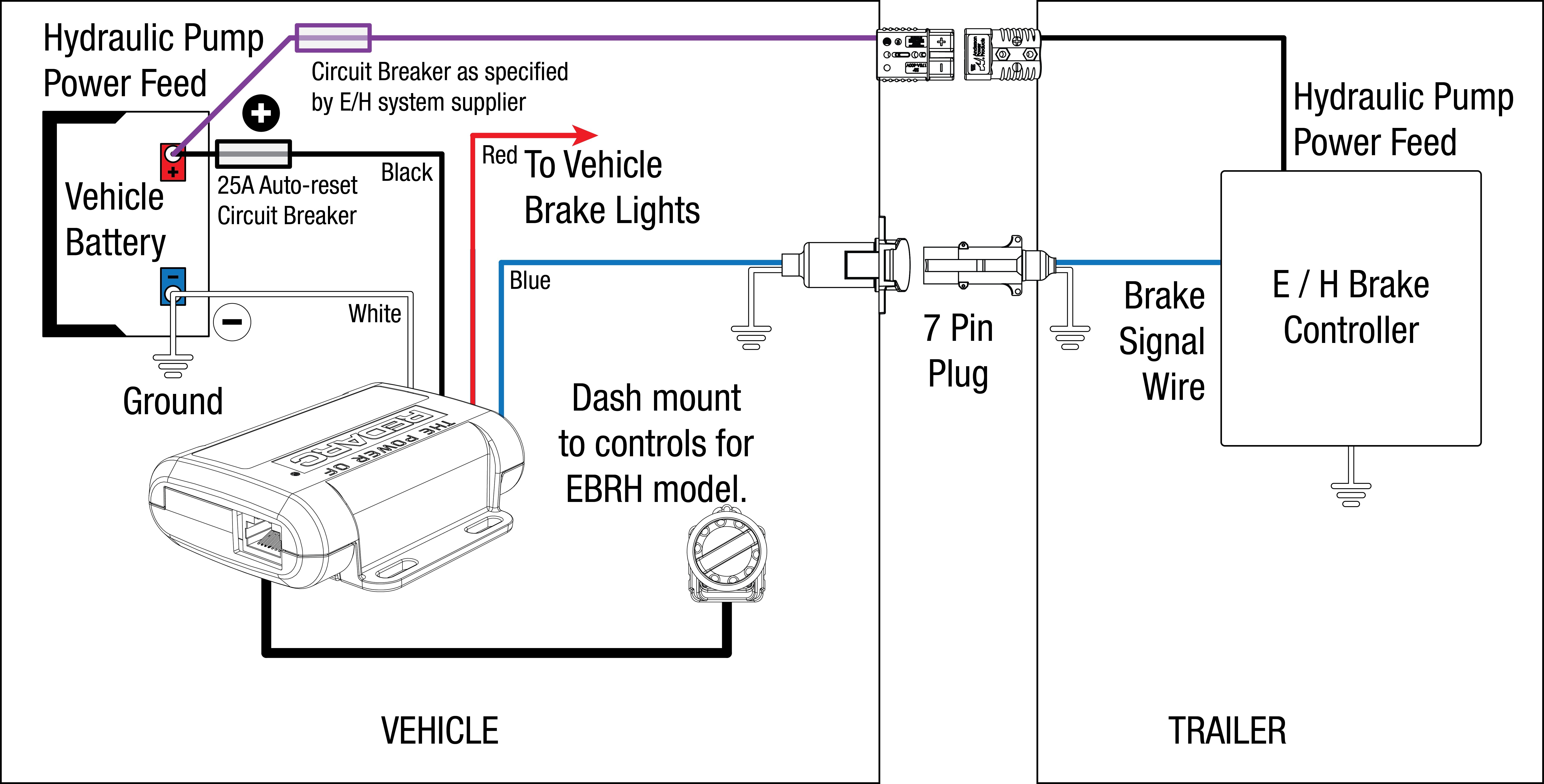
electrical - Does a brake controller need direct battery connection, or would a switched source ...
1. Splice one of the two wires coming out of the breakaway switch into the trailer brake wire running from the trailer connector to the brakes. 2. Open the battery box and connect the second wire coming out of the switch to the positive post (red) on the battery. This connection will send power to the breakaway switch.

11 Creative Hopkins Trailer Breakaway Wiring Diagram Photos - Tone Tastic
A trailer wiring harness is a length of wire at the back of a vehicle that allows its electrical system to connect to a trailer. Integrated with the vehicle's existing wiring, it provides a standard connector, such as a 4-way flat plug. A trailer wiring harness is one of the most vital towing parts but can often be overlooked.

wiring.gif.pagespeed.ce.w4frxP_GUv - Car Mate Trailers, Inc
Figure 4 - Wiring Diagram Refer to the wiring diagram shown in Figure 4 as you follow the electrical connection instructions below. Plan ahead by starting with long wires. All wires must be a least No. 12 AWG and insulated. The final length of the wires from the trailer, including the connector, should be longer than the safety chains.

Trailer Breakaway Switch Wiring Diagram
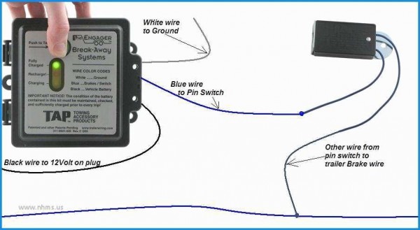
The Engager™ Break-Away System is designed to bring trailers safely to a stop wire coming from the trailer side connector (A - see diagram on next page). Test your Break-Away Kit before each outing as described in Step 5 of the wiring . How to Wire Break Away Switch on Hopkins Engager Break Away System.

3 Wire Trailer Breakaway Switch Wiring Diagram | Trailer Wiring Diagram
May 5, 2009 — Splice one blue wire of the Break-Away Switch to the electric brake wire coming from the trailer side connector (A - see diagram on next ...2 pages

Wiring Diagram For Trailer Breakaway Switch | Trailer Wiring Diagram
The breakaway switch is mounted to the A frame. The switch holds a pin on the end of a cable, which is then connected to the tow vehicle. If the vehicle separates from the caravan the pin is pulled from the switch and the breakaway system will be engaged, applying the electric brakes and brake lights.

Trailer Breakaway Battery Wiring Diagram - Trailer Wiring ...
post or other suitable location within reach of the breakaway switch, ensuring that the case dos not impede the switch's lan-yard. 5. Install the breakaway battery into the case, ensuring that the battery is properly charged. WIRING Note:Refer to the attached wiring diagram for addi-tional information. Breakaway Switch: 1.
Trailer Brake Breakaway Wiring Diagram - Complete Wiring Schemas
Step 5. Locate the trailer connector's blue wire that supplies power to the electric brakes. You may have to cut into the trailer wiring's sheathing to find the wire. Connect the breakaway switch's other lead to the blue wire with a Scotchlok connector. If necessary, extend the wire from the trailer breakaway switch with 14-gauge automotive ...

man swimming in spring
We have a online diagram that will help you understand how the break away system is wired into your trailer. It is actually a simple installation. The system splices into the existing trailer wiring. The break away box will have 3 wires coming out of it, a black, a white, and a blue wire. The Black wire would tap into the 12 Volt accessory lead ...

Trailer Wiring Diagram Brake-Away | Trailer Wiring Diagram
breakaway switch black cable brown white blue ground 7 way, 6way or 4 way plug c b pj trailers - utility trailer wiring diagram. 7 way plug vehicle running lights (brown) + auxilary right turn/ stop green backup lights electric brakes (blk/blue) trailer - ground (white) left turn 1 stop (yellow) 6 way plug vehicle electric brakes running lights ...

Trailer Wiring Diagram With Breakaway Switch | Trailer Wiring Diagram
Page 198: Trailer Wiring General Machine Schematics Mobile Generator 23.2 Trailer Wiring Standard and Hydraulic Brakes Electric Brakes Br W – Br W Br W w c _ g r 0 0 0 5 2 2 wc_gr000523... Page 199: Trailer Wiring Components
Wiring Diagram for the Curt 4 Pole to 7 Pole Adapter # C57674 And Wiring for Trailer Brakes ...
This Trailer Wiring Diagram With Breakaway Switch version is much more suitable for sophisticated trailers and RVs. It can transfer electricity better compared to the connector is suggested for higher-level electric in the car. Here is the diagram for 7-pin connector. White Pin for the floor.

Trailer Breakaway Kit Wiring Diagram | Trailer Wiring Diagram

white and yellow ice cream with cone

27 Trailer Breakaway Switch Wiring Diagram - Wiring Diagram List

voyager trailer brake controller wiring diagram - Wiring Diagram

Trailer Brake Wiring Diagram With Brakes - Database - Wiring Diagram Sample
Breakaway Switch Diagram for Installation on a Dump ...

Trailer Breakaway Wiring Schematic | Free Wiring Diagram

Trailer Breakaway Wiring Schematic - Wiring Diagram

34 Trailer Breakaway Kit Wiring Diagram - Wire Diagram Source Information

person holding black digital device

Breakaway Trailer Brake Wiring Diagram | Trailer Wiring Diagram
Instructions to Wire a Trailer for Electric Brakes | etrailer.com
trailer breakaway switch wiring diagram - Wiring Diagram

gray concrete statue of a man
![[DIAGRAM] Utility Trailer Ke Wiring Diagrams FULL Version HD Quality Wiring Diagrams ...](https://trailer-wiring-diagram.com/wp-content/uploads/2019/02/tekonsha-ke-controller-wiring-diagram-manual-e-books-wiring-diagram-for-trailer-breakaway-switch.jpg)
[DIAGRAM] Utility Trailer Ke Wiring Diagrams FULL Version HD Quality Wiring Diagrams ...

Trailer Breakaway Kit Wiring Diagram | Trailer Wiring Diagram

Trailer Wiring Diagram With Breakaway Switch | Trailer Wiring Diagram
The Engager Breakaway System Wiring Diagram


Comments
Post a Comment