41 york wiring diagram
YORK INTERNATIONAL 11 LD10915 DISPLAY INTERFACE BOARD FIG. 5 - DISPLAY INTERFACE BOARD NOTES: 1. This wiring diagram describes the standard elec tron ic con trol scheme for use with a YORK V.S.D. for details of standard modi fi cations, refer to Product Form 160.54-PW7. 2. Field wiring to be in accordance with the National Diagram, Wiring. Not applicable to specified model. H2RDS06B H2RDS06B H2RDS06B H2RDS06B. 1 . York Drive.York DNP Technical Manual. TYPICAL WIRING DIAGRAM NOTES All field wiring to be accomplished following city, local and/or national codes in effect at time of installation of this unit. Caution: Label all wires prior to disconnection when ser ...
YORK SOlutiOn AiR hAndling unitS Supersedes 102.20-N1 (1108) Form 102.20-N1 (1109) OutdOOR unit indOOR unit LD09624 LD09688 YORK SOlutiOn indOOR And OutdOOR MOdElS Renewal Parts Form 102.20-RP1 ith P/ n contact Balt. Parts Manufactured or specialty parts (800) 932-1701 contact Airside (800) 545-7814
York wiring diagram
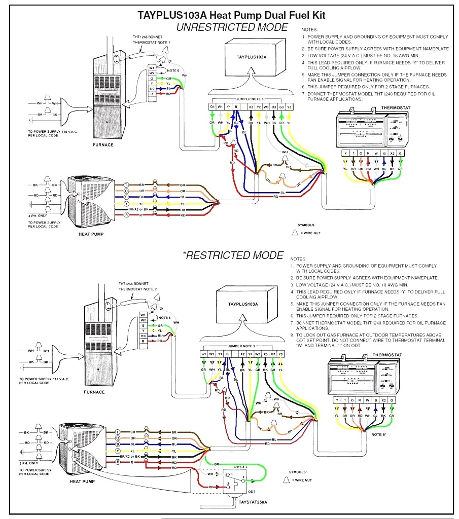
This wiring diagram describes the standard electronic control scheme for use with an YORK Electro-Mechan-ical Starter. For details of standard modifications. Refer to 160.75-PW4. 2. Field wiring to be in accordance with the National Electri - cal Code as well as all other applicable codes and speci-fications. See product form 160.75-PW1 for ... York Retail System Specific Wiring Diagrams York System Wiring Diagram WD 1. Optional. Optional. NOTES: If wires between the Air Handler and the Heat Pump is not possible W1 and W2 can be combined at the AH. York System Wiring Diagrams WD 3. Optional. Optional * . DISCLAIMER. This material is for professional use only and is intended to be used ... At YORK®, comfort is more than a feeling – it's a promise: to innovate, to assure and, most of all, to deliver. Find out how we leverage our unparalleled residential dealer network and world-class commercial support services to lead the industry. Residential Products. Residential Finance and Savings. Residential Warranties.
York wiring diagram. A wiring diagram is a streamlined standard pictorial depiction of an electrical circuit. York retail system specific wiring diagrams january 2012. Variety of york furnace wiring diagram. A wiring diagram is a type of schematic which uses abstract pictorial symbols to show all the affiliations of parts in a system. York system wiring diagrams wd 2. York Wiring Diagrams Air Conditioners wiring diagramsThermostat Wiring Diagrams Heat pumps are wired for HVAC control far differently than air conditioning systems so make sure you know the difference and correctly identify the type of HVAC system you have installed Thermostat Wiring Diagrams With the top diagram showing an air conditioning ... YORK® Predator® units are convertible single packages with a common footprint cabinet and common roof curb for all 6-1/2 through 12-1/2 ton models. All units have two compressors with independent refrigeration circuits to provide 2 stages of cooling. The units were designed for light commercial applications and YORK® Model ZE units are either single package cooling units equipped with optional factory installed electric heaters, or single package gas-fired central heating furnaces with cooling unit. Both are designed for outdoor installation on a rooftop or slab. The units are completely assembled on rigid, permanently attached base rails.
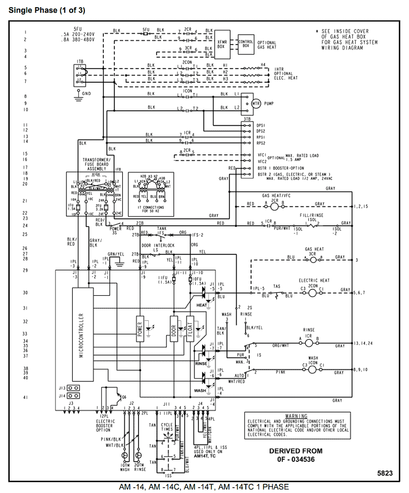
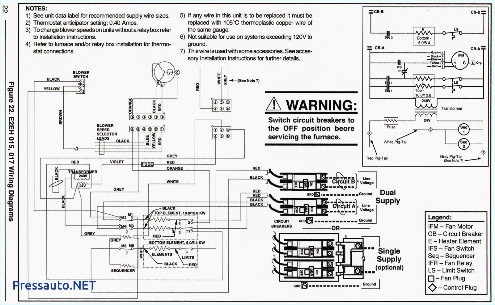
York 5 Ton Package Unit Wiring Diagram D6nz060. GENERAL. YORK Model D1NA and D2NA units are cooling/heating air con- SERIES. SINGLE PACKAGE AIR CONDITIONERS /2 THRU 5 TON. (10 SEER) .. ment wire must be of the type shown on the wiring diagram. Electrical line. The complete connection diagram and schematic wiring label is located on the inside surface of the unit service access panel. FIELD CONNECTIONS POWER WIRING. 1.16 pages York PCG4 Series Manual Online: Connection Wiring Diagram - 3.5 To 5 Ton Models. Johnson Controls Unitary Products 1183746-UIM-B-0215 CAUTION - OPEN ALL ... Re: York Wiring Diagrams. Reset the chiller this afternoon, and managed to run it up eventually. The contacts are OK and the HP OK, I have put it down to a suspected refrigerant leak. Al I've sent you a seperate message. Thanks. a problem shared is a problem halved. 06-04-2010, 05:23 PM #10. nicolaas.
York Heat Pump Wiring Help Doityourself Com Community Forums. York Xp Sunline R410a 13 Seer Wiring Diagram. York Predator Dm150 User Manual Page 36 Also For Dm090 Dm120. Typical Wiring Diagrams Zh Zj037 150 York Predator R 410a User Manual Page 106 135. Figure 1 7 Air Conditioner Wiring Diagram Sheet Of 3. 5020803-UIM-E-1115 4 Johnson Controls Unitary Products LOCATION Use the following guidelines to select a suitable location for these units: 1. Unit is designed for outdoor installation only. 2. User manual |. York D2CE Operating instructions. ® INSTALLATION INSTRUCTION SUNLINE 2000 ELECTRIC / ELECTRIC & GAS / ELECTRIC SINGLE PACKAGE AIR CONDITIONERS (Constant Air Volume) 530.18-N11Y (399) Supersedes: 530.18-N11Y (195) 035-16133 MODELS D2CE & D2CG300 (8.5 EER) 208/230/575 VOLT ONLY 208/230/460 VOLT ONLY DCG MODEL SHOWN SAFETY ... York furnace manuals should always be kept after installation for future references. If your York furnace manuals have been misplaced or are otherwise inaccessible, don't sweat! HVAC.com has you covered - access your York furnace manuals online, as well as manuals for HVAC equipment manufactured by other leading brands.
York Air Handler Wiring Diagram
Wiring Diagram - YK Chiller (Style G) OptiView Control Center with Remote Low or Medium Voltage EMS 160.75-PW5 Wiring Diagram - YK Chiller (Style G) OptiView Control Center with Unit Mounted Low or Medium ... The YORK Model YK Chiller is commonly applied to large air conditioning systems, but may be used on other applications. The chiller ...
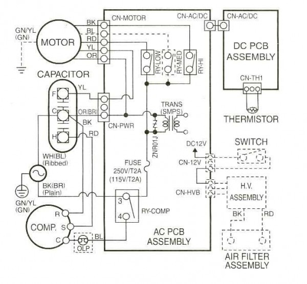
York Wiring Diagram H1dh030s06d
Old York Control wiring diagram If this is your first visit, be sure to check out the FAQ by clicking the link above. You may have to register before you can post: click the register link above to proceed.
York H1ra042s06d Wiring Diagram
The complete connection diagram and schematic wiring label is located on the inside surface of the unit service access panel.20 pages

York Thermostat Wiring Diagram
York Package Unit Wiring Diagram Gallery. york package unit wiring diagram - Exactly What's Wiring Diagram? A wiring diagram is a type of schematic which utilizes abstract photographic icons to show all the affiliations of parts in a system. Electrical wiring diagrams are made up of two points: icons that stand for the elements in the…

York Heat Pump Wiring Schematic - York Air Handler Wiring ...
This wiring diagram describes the standard elec tron ic con trol scheme for use with a YORK V.S.D. for details of standard modifications, refer to Product Form ...

Yst York Chiller Wiring Diagram - Wiring Diagram Schemas
York thermostat Wiring Diagram - wiring diagram is a simplified normal pictorial representation of an electrical circuit. It shows the components of the circuit as simplified shapes, and the knack and signal contacts amongst the devices. A wiring diagram usually gives assistance roughly the relative perspective and covenant of devices and ...
York Heat Pump Wiring Diagrams Readingrat Net In For ...
York D7CG 060 Air Conditioner User Manual. Open as PDF. of 20. GENERAL. YORK Model DCG units are single package air conditioners. with gas heat designed for outdoor installation on a roof top or. a slab. The units are completely assembled on rigid, permanently. attached base rails.

lighted high-rise buildings
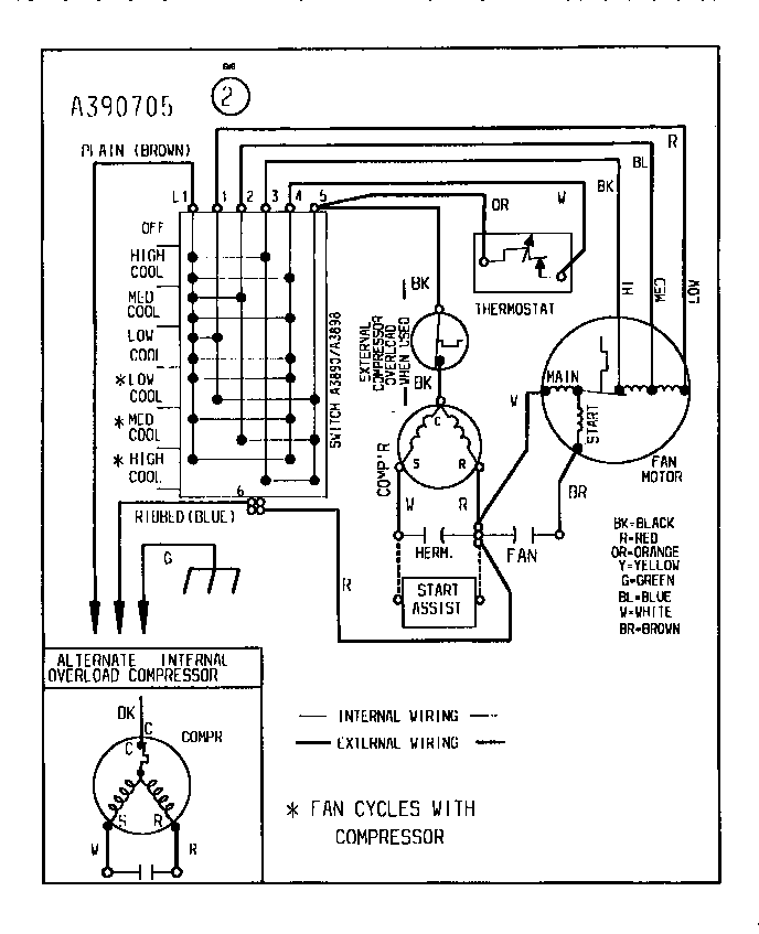
535678-UIM-B-0210 EFFICIENCY RATING CERTIFIED ISO 9001 Certified Quality Management System RESIDENTIAL GAS FURNACE WITH ECM MOTOR MODELS: TPLC*C, YPLC*C, CPLC*C, LPLC*C

York D4Cg120N20025Eca Wiring Schematic - EA_7004 York ...
Refer to the wiring diagrams below and choose the appropriate diagram. b. Connect the Black wire (Hot Line) to the Black wire of the photocontrol. c. Connect the Black wire of the light fixture to the Red wire of the photocontrol. d. For volt units: Connect the White wire from the light fixture and the White wire from the photocontrol to.

York Furnace Wiring Diagram - Wiring Diagram Schemas
FIGURE 13 - Elementary Wiring Diagram ..... 62 FIGURE 14 - Fan Wiring, Standard Low Sound Or Ultra Quiet, YLAA0070 - YLAA0516 ... YORK YLAA chillers are manufactured to the highest design and construction standards to ensure high per-formance, reliability and adaptability to all types of air ...

York Wiring Diagram H1dh030s06d
York Air Conditioner Diagram - Wiring Diagrams Hubs - York Air Handler Wiring Diagram Wiring Diagram contains many in depth illustrations that show the link of various things. It includes directions and diagrams for different varieties of wiring strategies and other items like lights, windows, and so on.

York Chiller Wiring Diagram / Yst York Chiller Wiring ...
Mar 14, 2018 · York Heat Pump Wiring Diagram Gallery. york heat pump wiring diagram - A Newbie s Overview to Circuit Diagrams An initial look at a circuit diagram may be complicated, however if you could check out a train map, you could read schematics. The purpose coincides: getting from point A to point B. Literally, a circuit is…

York Heat Pump Thermostat Wiring Diagram Het Pump - Wiring ...
HOW TO READ THE WIRING DIAGRAMS - Wire Colour Codes A-9 WIRE COLOUR CODES Wire colours are identified by the follow colour codes. Code Wire colour Code Wire colour B Black P Pink BR Brown R Red G Green SB Sky blue GR Gray SI Silver L Blue V Violet LG Light green W White O Orange Y Yellow If a cable has two colours, the first of the two colour code

city skyline
York System Wiring Diagrams WD 2. IAQ 9000. NOTES: If 10-wires between the Air Handler and the Heat Pump is not possible W1 and W2 can be combined at the AH. with a jumper eliminating W2 out and staged electric heat. X/L can be eliminated as the fault codes can be retrived from the board.
30 York Furnace Wiring Diagram - Wiring Diagram Database
DOWNLOAD. Wiring Diagram Images Detail: Name: york rooftop unit wiring diagram - Wiring Diagram For A Ac Unit Valid Outstanding York Rooftop Wiring Diagrams Ornament Simple Wiring. File Type: JPG. Source: rccarsusa.com. Size: 704.12 KB. Dimension: 1696 x 2200. DOWNLOAD. Wiring Diagram Sheets Detail:

York Rtu Wiring Diagrams Pdf - Wiring Diagram and ...
Dec 17, 2018 · York Retail System Specific Wiring Diagrams York System Wiring Diagram WD 1. Optional. Optional. NOTES: If wires between the Air Handler and the Heat Pump is not possible W1 and W2 can be combined at the AH. York System Wiring Diagrams WD 3. Optional. Optional * . York Heat Pump Model E1RAS06D Parts - Shop online or call Fast shipping.

Collection Of York Rooftop Unit Wiring Diagram Download
We have 191 Chevrolet Vehicles Diagrams, Schematics or Service Manuals to choose from, all free to download! 1923 chevrolet car wiring [846 KB] 1923 chevrolet general wiring [321 KB] 1923 chevrolet superior model [290 KB] 1923 chevrolet wiring [237 KB] 1925 chevrolet superior model series k [910 KB] 1927 chevrolet capitol and national [365 KB]

York Rtu Wiring Diagram - York Zf300 Specifications ...
York Retail System Specific Wiring Diagrams. York d1na018 d2na060 page 17 heat pump wiring help zr series diagrams pdf yze installation manual yk diagram take a look at this air conditioner sheet diamond 80 gas furnace new and service manuals for typical sun pro rheem thermostat aprilaire 560 tm9x how to replace condensor fan motor as millennium ycas0130 users chart maytag cre9600acl timer ...
Wiring Diagram York Gas Furnace I Have | Manual E-Books ...
All wiring must be in accordance with the National and Local Each heater has a wiring diagram affixed to the inside of the access door. Consult this diagram before making. QMark is a leading brand of residential and commercial heaters and ventilation systems. View and Download Qmark MUH Series installation & maintenance instructions manual online.

York Furnace Wiring / Hvac C Wire To Thermostat Confusion ...
12. Refer to the following wiring diagrams for addi-tional information: FORM DESCRIPTION 160.76-PW6 YORK control center 160.76-PW4 Field wiring modifications 160.00-O1 160.00-O4 YORK Variable Speed Drive 160.00-O10

York Model H2rd036s06b Wiring Diagram
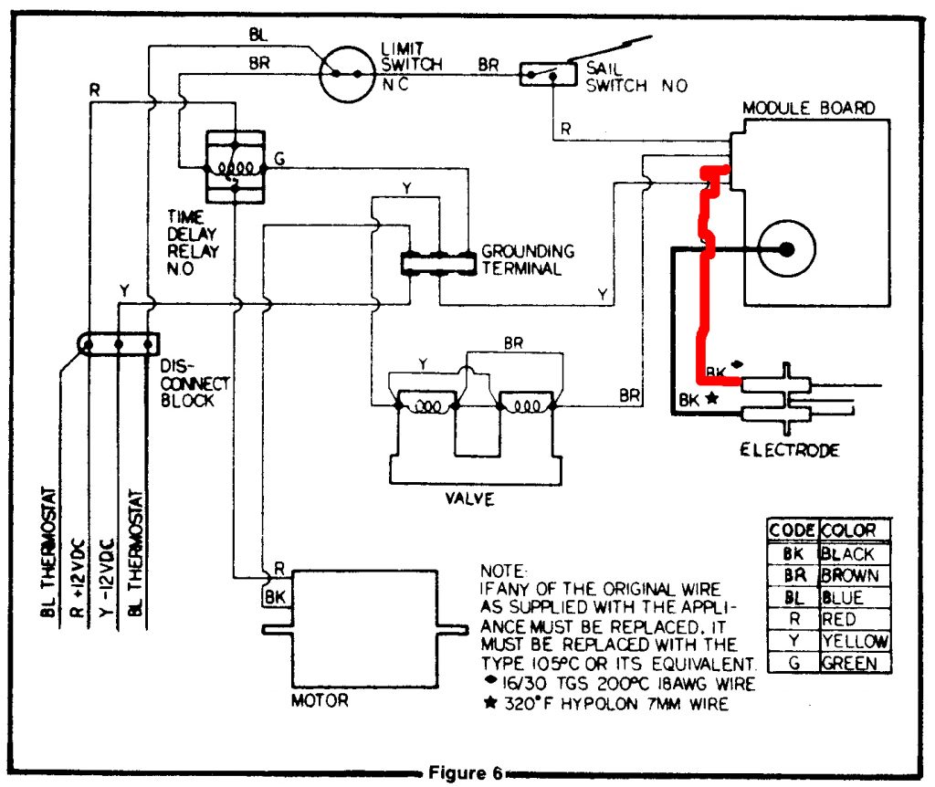
1083163-UIM-C-0715 2 Johnson Controls Unitary Products SECTION I: SAFETY This is a safety alert symbol. When you see this symbol on labels or in manuals, be alert to the potential for personal

York Yt Chiller Wiring Diagram Download
See attached pdf file explaining the purpose of each wire for our Standard DC Output cord found on QuiQ series chargers. If you have additional questions, search for the information in our suppor...

York Condenser Wiring Diagram Download
York Wiring Diagrams wiring diagram is a simplified within acceptable limits pictorial representation of an electrical circuit. White wire for heating system if so equipped. Wiring Diagram YK Chiller Style G OptiView Control Center with Unit Mounted Low or Medium Voltage SSS Unit Mounted Low Voltage VSD with Modbus or Remote Medium Voltage VSD ...

York Furnace Wiring Diagram Basic - Old York Furnace ...
York System Wiring Diagrams WD 2. IAQ 9000. NOTES: If 10-wires between the Air Handler and the Heat Pump is not possible W1 and W2 can be combined at the AH. with a jumper eliminating W2 out and staged electric heat. X/L can be eliminated as the fault codes can be retrived from the board.

Get York Condensing Unit Wiring Diagram Sample
At YORK®, comfort is more than a feeling – it's a promise: to innovate, to assure and, most of all, to deliver. Find out how we leverage our unparalleled residential dealer network and world-class commercial support services to lead the industry. Residential Products. Residential Finance and Savings. Residential Warranties.

buildings during night time
York Retail System Specific Wiring Diagrams York System Wiring Diagram WD 1. Optional. Optional. NOTES: If wires between the Air Handler and the Heat Pump is not possible W1 and W2 can be combined at the AH. York System Wiring Diagrams WD 3. Optional. Optional * . DISCLAIMER. This material is for professional use only and is intended to be used ...

York Furnace Wiring | Wire
This wiring diagram describes the standard electronic control scheme for use with an YORK Electro-Mechan-ical Starter. For details of standard modifications. Refer to 160.75-PW4. 2. Field wiring to be in accordance with the National Electri - cal Code as well as all other applicable codes and speci-fications. See product form 160.75-PW1 for ...

York Thermostat Wiring Diagram Perfect Images York Heat ...

Wiring Diagram For York Heat Pump - Database - Wiring ...

Wiring Diagram For York Heat Pump To Nest Thermostat ...

York Hvac Wiring Diagram : York Thermostat Wiring Diagram ...

York Model H2rd036s06b Wiring Diagram

York Thermostat Wiring

York Ga Furnace Control Board Wiring Diagram - Wiring ...

York Ac Compressor Wiring Diagram - EZATYNAMAKU
Goodman Heat Pump Air Handler Wiring Diagram : York Air ...

York Condenser Wiring Diagram Download

Residential Air Conditioner Wiring Diagram Sample

York Air Handler Wiring Diagram | Free Wiring Diagram

York Heat Pump Wiring Diagram H2Ra0600S06D - Collection ...

York Heat Pump Wiring Diagram | Free Wiring Diagram


Comments
Post a Comment