42 cooper dimmer switch wiring diagram
Nov 03, 2020 · Cooper 3 Way Dimmer Switch Wiring Diagram Source: www.doityourself.com. Before reading a schematic, get common and understand all the symbols. Read typically the schematic like a new roadmap. I print the schematic in addition to highlight the circuit I’m diagnosing in order to make sure I am staying on the particular path. Check out the diagram below that shows how to way a three way switch: When wiring a Lightwave RF master dimmer to a slave, the voltage isn't mains voltage it's.There are no markings on the back of the dimmer switch, and on the back of the new switch I've got 3 points -COM, L1 and L2.
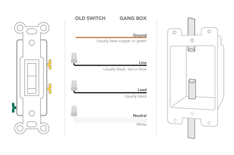
If you are replacing an existing 3-way switch: When replacing an existing 3-way switch take note of how the existing switch is wired BEFORE you remove the wiring, then refer to your notes to help you wire the new 3-way dimmer switch. Many manufacturers are now producing dimmer switches that can be used for either Single Pole or 3-Way Switches.

Cooper dimmer switch wiring diagram
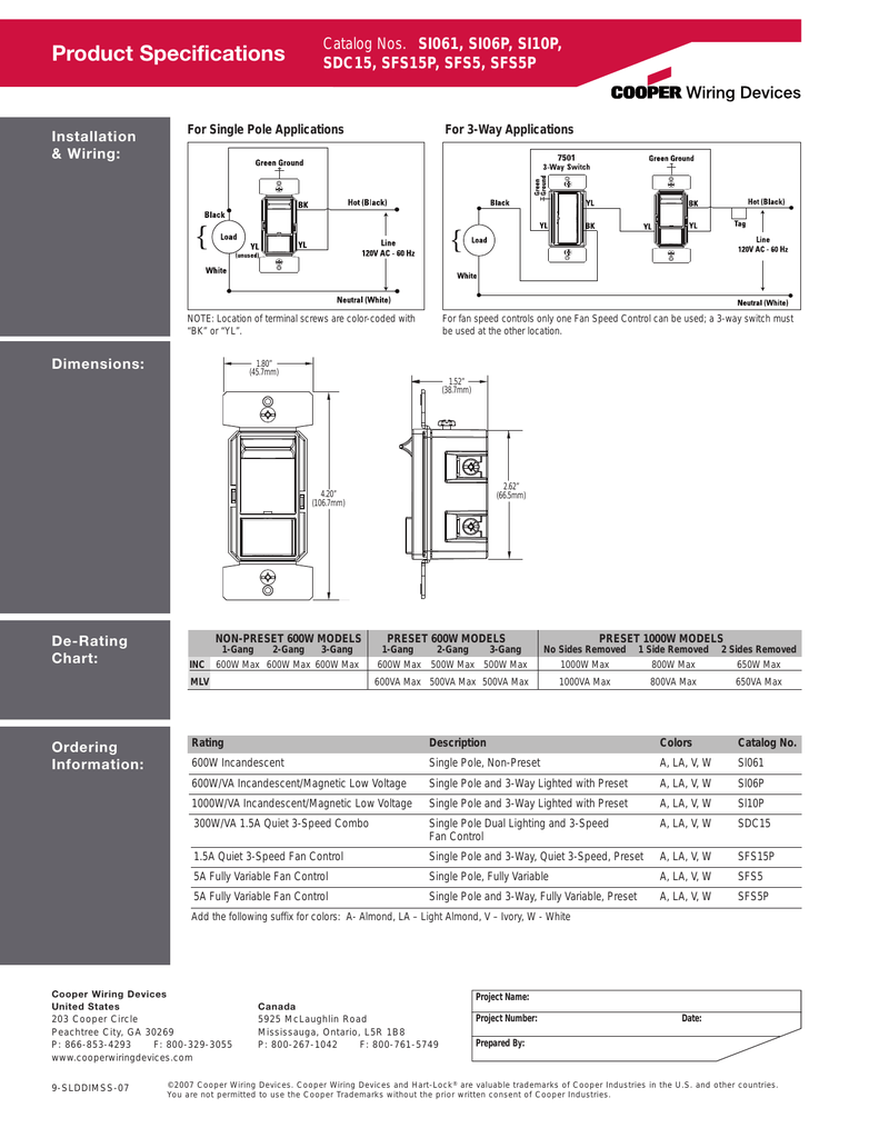
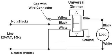
A wiring diagram is a simple visual representation from the physical connections and physical layout associated with an electrical system or circuit. Weg motor capacitor wiring diagrams schematics and baldor diagram in. Baldor reliance industrial motor wiring diagram new wirh baldor. Baldor motor capacitor wiring diagram a novice s overview of ... FIGURE 1: SINGLE POLE WIRING DIAGRAM TOP Green or Bare Slider Black Thumbwheel V iole t Gray LOAD VT GY BK YL YL Line 120 VAC - 60 Hz Neutral White Black Hot Travellers Tag FIGURE 2: 3-WAY WIRING DIAGRAM 3-WAY SWITCH DIMMER TOP Green or Bare Slider Black Thumbwheel Vi olet Gray VT GY LOAD * Visit our website for additional wiring details at ... Leviton Ip710-lfz Wiring Diagram. Leviton single pole dimmer switch wiring diagram. If you are using a dimm. Step 4 Connect wires per WIRING DIAGRAM as follows. Youll be able to often depend on Wiring Diagram being an crucial reference that can help you save money and time. Here is a picture gallery about leviton timer switch wiring diagram ...
Cooper dimmer switch wiring diagram. Cooper is a registered service mark of Nationstar Mortgage LLC. Basic Safe Electric Fuel Pump Wiring Diagram This is the basic wiring diagram for SAFE electric fuel pump wiring. Wiring devices & connectivity, Eaton is a power management company with 2018 sales of $21.6 billion. 0-10V Slide Dimmer Wallstation Overview The 0-10 Volt Slide Dimmer provides full-range classic linear-slide dimming for 0-10V compatible dimmable light sources. These units are ideal for light commercial applications and are compatible with decorator style devices and wallplates. The preset "ON/OFF" switch Cooper dimmer switch wiring diagram. Connect Accessory Dimmer 1 in the location of the other 3-way Switch as indicated in the diagram using the wire nuts provided. Verify all wiring connections 4. Residential Ers Guide Section B. The switch it is connected to is a dimmer switch with an onoff button as well as a dimmer slider. Idrabo Wall dimmer Switch, Dimmer Switch for Dimmable LED, Halogen and Incandescent Bulbs Single-Pole or 3-Way,120V AC, White. 4.3 out of 5 stars. 174. $11.99. $11. . 99. Get it as soon as Thu, Oct 28. FREE Shipping on orders over $25 shipped by Amazon.
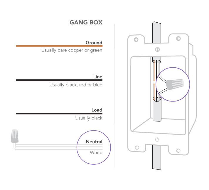
Cooper 3 way light switch wiring diagram. 4-way switch diagrams are purposed to illustrate the 4 way switch wiring which is used control lights with three or more switches. Lighting Wiring Additional Light To A 3-Way Switch Switch. Effectively read a wiring diagram one provides to find out how the components inside the system operate. Wiring Diagram Example Recommended DImmer Switches* Note, these diagrams are only examples. You should refer to the instructions included with your dimmer switch. * Most 0-10V dimmers include an integrated switch, button or rocker to completely turn off power to the fixture. Aubuchon Hardware : Dimmer Switch . Ivory three way rotary dimmer that sets the mood with lighting. Saves energy and extends lamp life. Attractive stylized knob provides dimming, on/off control and indication of light level setting.Aubuchon Hardware : Dimmer Switch . E6000 is formulated to meet high performance industrial requirements. The self-leveling formula forms a … Single Pole Wiring Diagram, INC 3-Way Wiring Diagram, INC HOT 120V AC NEUTRAL WHITE BLACK B K BLAC K GREEN Single Pole Wiring Diagram, Fully Variable Fan Single Pole Wiring Diagram, INC/3-Speed, 4-Speed & Fully Variable Fan Wiring Diagrams Rotary dimmers & fan controls Electrical Sector 203 Cooper Circle Peachtree City, GA 30269 United States ...
For single pole applications wire the sensor switch according to wiring diagram 1 using the wire nuts provided. Cooper Tr274 Wiring Diagram. Disconnect the 3-way switch that will be replaced by the dimmer. Single-Pole Wiring Diagram 3-Way Wiring Diagram Wiring Diagrams Certifications & Compliances KEY: cULus NOM Title 20 compliant Catalog No. DF10P • • • DCK1 • • • Compliances, specifications and availability are subject to change without notice. Electrical Sector 203 Cooper Circle Peachtree City, GA 30269 United States Eaton.com Cooper 3 Way Dimmer Switch Wiring Diagram Yellow Wire. I went bavk and looked at it. Check all of the wires to make sure that they are all in good condition. electrical - Trying to add a light at the end of a 3-way ... (Alex Barton) Three-way switches have different methods of connection, depending on the brand of the switch. These wires come ... Greengate ControlKeeper. A cost-effective, specification grade lighting control system composed of control panels (up to 48 relays per panel) with optional programming touchscreen and low voltage inputs for momentary, maintained switches, occupancy sensors and photocells. Explore System Products.
Cooper Lighting 0-10V Preset Slide Dimmer Installation ...
What are Wiring diagram 3 way motion detector schematron.org detector switch how to wire a cooper 3-way motion detector switch to be compatible with a. Cooper wiring diagram single pole light switch explained bination double leviton three way dimmer switch wiring diagram fresh cooper 3 for with wiring diagram cooper 3 way switch refrence.

Cooper Wiring Devices DRP CWD FULL NITE LITE PRGRMBL in the ...
0-10V dimming wiring diagram 0-10V dimmer switch Leviton IP710-LFZ or equal For other types of dimming control systems, consult controls manufacturer for wiring instructions switched hot (black) switched hot (red typical) low voltage dimming wires (purple & gray typical) + Electrical Panel hot (black typical) 120V or 277V, 60 Hz

Wiring Diagram Lighting Circuit Joint Box Method - Great for Wiring to LED Downlights (Spotlights)
May 22, 2020 · Cooper Dimmer Switch Wiring Diagram. To properly read a electrical wiring diagram, one offers to know how typically the components in the program operate. For instance , when a module is powered up and it also sends out a new signal of fifty percent the voltage in addition to the technician does not know this, he'd think he offers a challenge ...
Technical Datasheet
The 0-10V Decorator Dimmer provides full-range classic linear-slide . dimming for 0-10 Volt compatible dimmable light sources. These units are ideal for light commercial applications and are compatible with decorator style devices and wallplates. Units feature a preset "ON/OFF" switch that automatically returns controlled light(s) to
Classic Mini - Wiring Spots and Lamps - Problems, Questions ...
network. 2. To include this device in a Z-Wave network, select the command. on your Z W ave controller for inclu sion (Install, A dd Device, Add. Node, Include Devic e, etc.). Then p ress the device s witch one. time to include it in the network. 3. Based on the controller, the controller may ask to scan the QR.
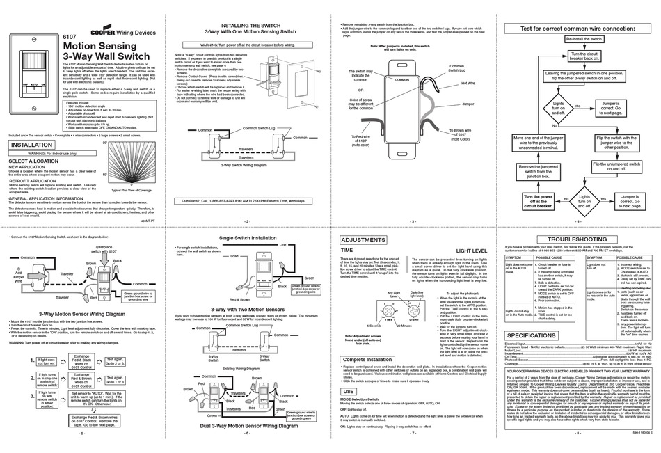
COOPER WIRING DEVICES 6107 INSTALLATION Pdf Download | ManualsLib
SWITCH DIMMER YL Black Thumbwheel TOP Green or Bare White Thumbwheel Slider 3-Way Wiring Diagram INC, HAL, LED/CFL, FLR, MLV, ELV Wiring Diagrams Notee:Location of terminal screws are color-coded with "BK" or "YL". Notee:3-way switch must be used at the other locations. Certifications & Compliances KEYe: cULus NOM Catalog No. DAL06P ...

Zooz Z-Wave Switch Wiring Help : r/homeautomation
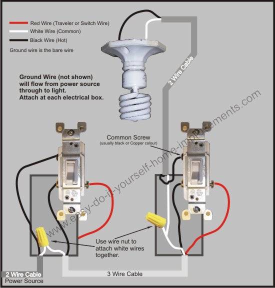
Nov 28, 2021 · Cooper wiring 3 way switch diagram. This 3-way light switch wiring diagram shows how to do the light switch wiring and the light when the power is coming to the light fixture. This wiring diagram shows both switches aligned together with the fixture at the end. Lutron 3 Way Dimmer Switch Wiring Lutron 3 Way Dimmer Wiring Installing A Light ...
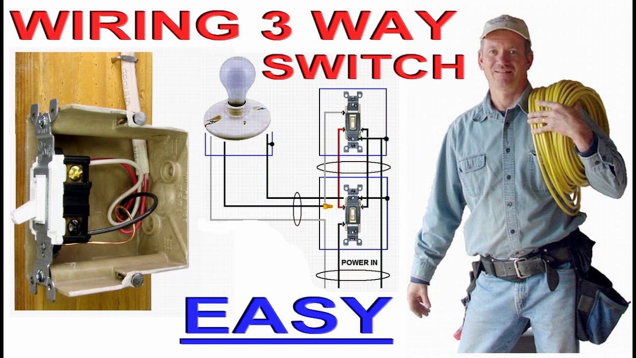
How to Wire a 3 Way Dimmer Switch
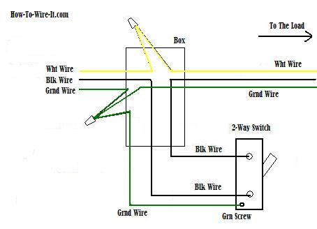
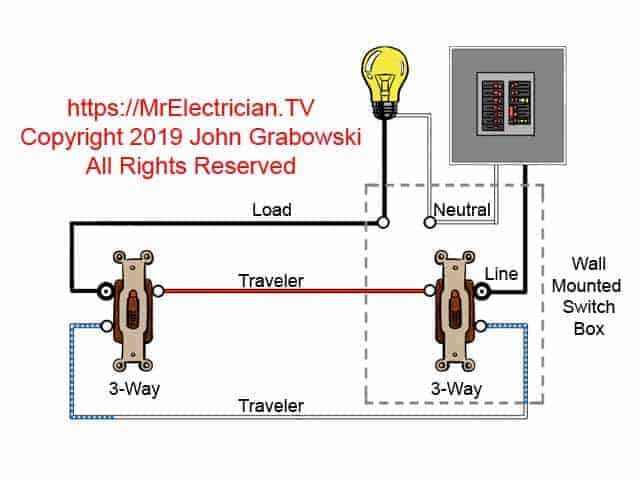
3-way Dimmer Wiring In the diagram below, a 2-wire NM cable supplies power from the panel to the dimmer box. The black (line) wire connects to the common terminal of the 3-way dimmer. A 3-wire NM connects the travelers of the dimmer to the travelers of the 3-way switch. Traveler wires are interchangeable on each switch.
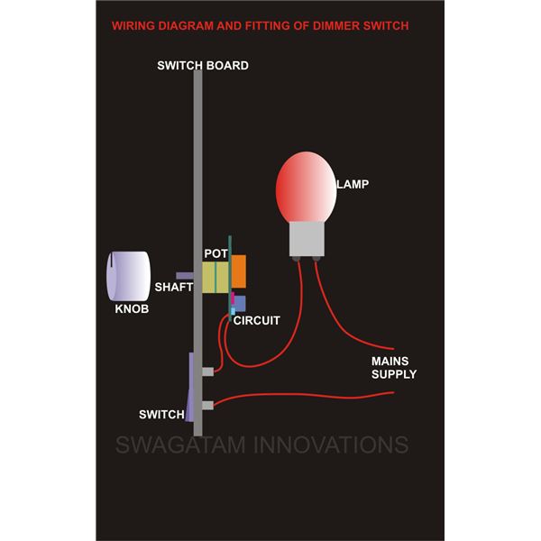
How to Install A Dimmer Switch
5/8 in (16 mm) for 16 and 18 AWG (1.0 or 0.75 mm2) wire 3. Using wire connectors supplied, make connections following the appropriate wiring diagrams for your combination of controls and ballasts. 4. Carefully push wires into wallbox, allowing room for dimmer backcover. Do not pinch wires. 5. WhiteMount dimmer to wallbox using screws provided ...
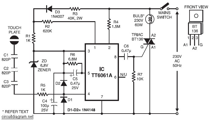
220V AC Lamp Touch Dimmer | Electronic Schematic Diagram
4 Way Dimmer Switch Wiring Troubleshooting. angelo on September 11, 2021. Wiring Diagram Fan Light Kit And 3 Way Switches Light Switch Wiring Ceiling Fan With Light Fan Light Switch. Wiring Diagram For 3 Way Switch With 4 Lights Bookingritzcarlton Info Light Switch Wiring 3 Way Switch Wiring Home Electrical Wiring.

Smart Switches - No Neutral Wire? - IOT & Smart Technology
… wiring diagram motion light further 3 way dimmer switch wiring dead end 3 way switch also cooper motion sensor wiring Manual Override Wiring Learn the fine art of motion detector sensor adjustment and stop wasting energy illuminating Adjust Motion Detectors.

Installation problem on Cooper Ind AAL06-C2-K-L Smart Dimmer ...
Leviton Ip710-lfz Wiring Diagram. Leviton single pole dimmer switch wiring diagram. If you are using a dimm. Step 4 Connect wires per WIRING DIAGRAM as follows. Youll be able to often depend on Wiring Diagram being an crucial reference that can help you save money and time. Here is a picture gallery about leviton timer switch wiring diagram ...
0-10V Decorator Dimmer Wallstation
FIGURE 1: SINGLE POLE WIRING DIAGRAM TOP Green or Bare Slider Black Thumbwheel V iole t Gray LOAD VT GY BK YL YL Line 120 VAC - 60 Hz Neutral White Black Hot Travellers Tag FIGURE 2: 3-WAY WIRING DIAGRAM 3-WAY SWITCH DIMMER TOP Green or Bare Slider Black Thumbwheel Vi olet Gray VT GY LOAD * Visit our website for additional wiring details at ...
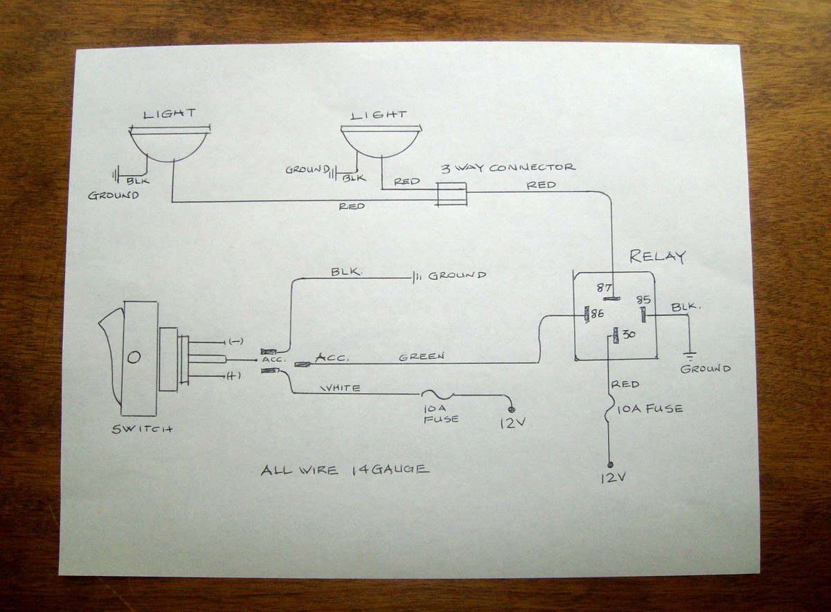
How To Wire Driving/Fog Lights – Moss Motoring
A wiring diagram is a simple visual representation from the physical connections and physical layout associated with an electrical system or circuit. Weg motor capacitor wiring diagrams schematics and baldor diagram in. Baldor reliance industrial motor wiring diagram new wirh baldor. Baldor motor capacitor wiring diagram a novice s overview of ...
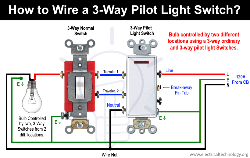
How to Wire a Pilot Light Switch? 2 and 3 Way Wiring
Results page 126, about 'infrared remote control for fan ...

SOLVED: Cooper S106P dimmer switch - Fixya
How to wire a smart switch

diagram schematic: Study Switches Wired Diagram

Single-pole switch | TREATLIFE
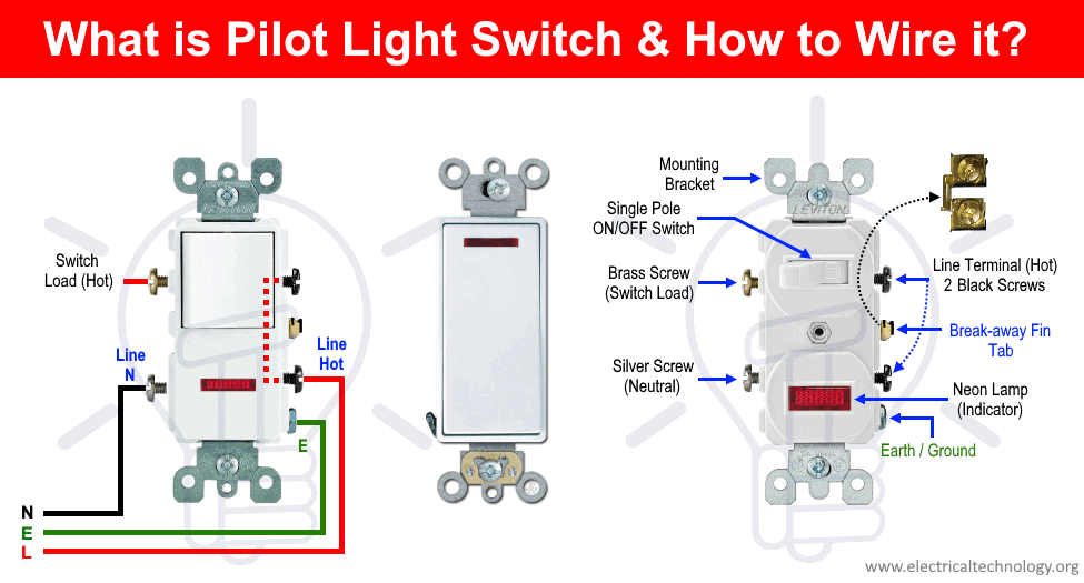
How to Wire a Pilot Light Switch? 2 and 3 Way Wiring

20 Most Recent Cooper Wiring Devices Aspire Smart Questions ...
3 Way Switch Wiring Diagram
Lutron Dimmer Switch Wiring Diagram on PopScreen

Cooper 277 pilot light switch | Light switch wiring ...
How to Install a Dimmer Light Switch: Wiring and Replacement ...
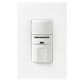
Cooper Wiring Devices OS106D1-W 600W PIR Occupancy Sensor Dimmer Switc
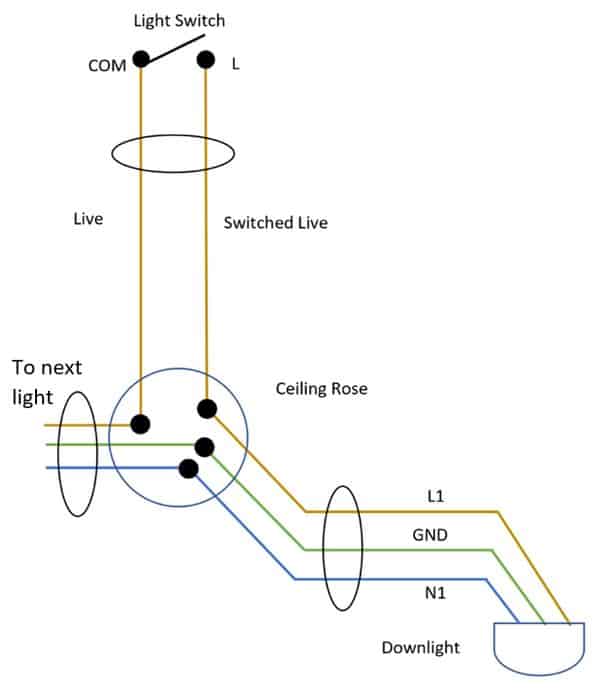
How To Wire Downlights To A Switch: Simple Diagram - LED ...
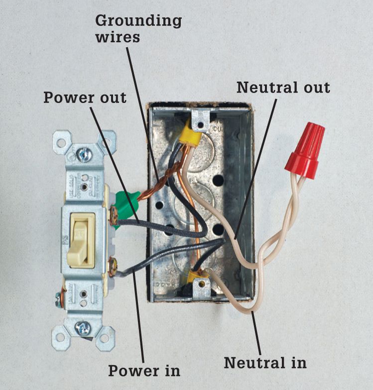
Installing Dimmer Switch - Single Pole – Customer Support
How to use a 14/2 wire to wire a light with 2 switches - Quora
/7-Attach-Wires-to-Dimmer-56a49e863df78cf772834c1f.JPG)
How to Install a Single-Pole Dimmer Light Switch

Single Pole Decorator Wall Switch 7501
How to use a 14/2 wire to wire a light with 2 switches - Quora

How to setup Dimmable LED High Bay or LED Parking Lot Lights ...
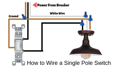
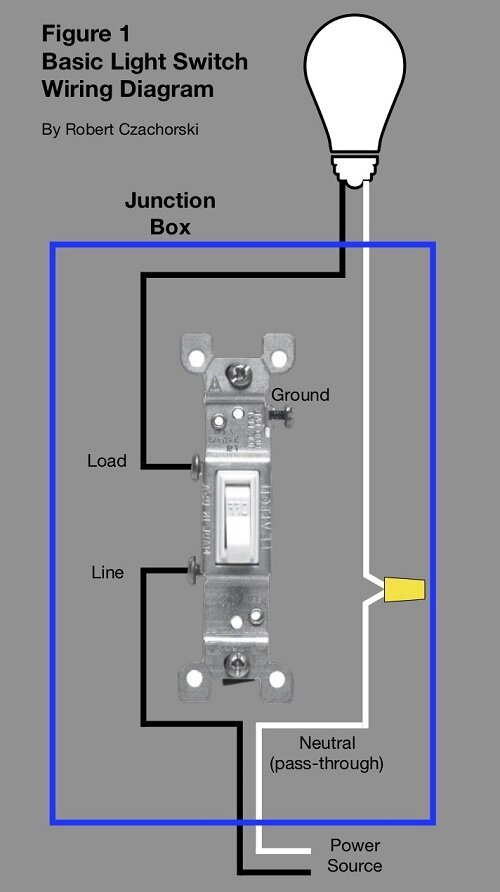
How to Wire a Light Switch - Very Easy - Lighting Tutor
Switches - The Complete Guide to Wiring - Black & Decker ...

How to wire occupancy sensor and motion detectors

Wire A Switch
Installing Dimmer Switch - Single Pole – Customer Support

How to wire Cooper 277 pilot light switch | Light switch ...
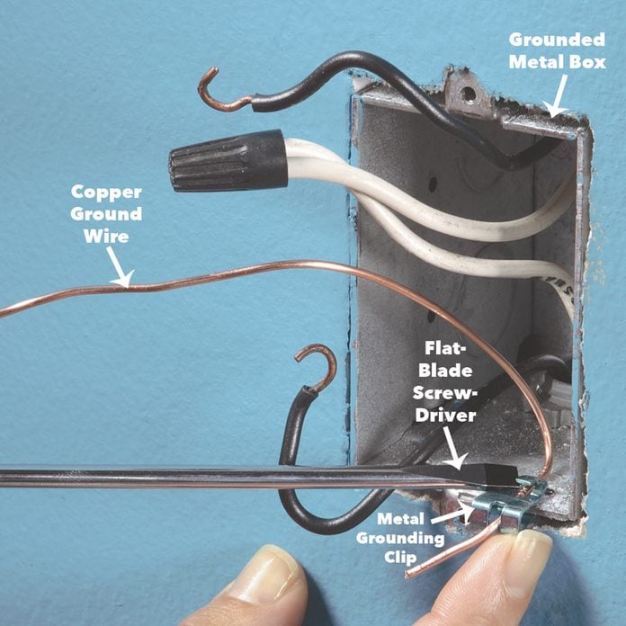
New Dimmer Switch Has Aluminum Ground - Can I Attach To ...
Three-Way Switch Wiring Diagrams


Comments
Post a Comment