42 entropy temperature diagram
A locked padlock) or https:// means you've safely connected to the .gov website. Share sensitive information only on official, secure websites. Explore thousands of free applications across science, mathematics, engineering, technology, business, art, finance, social sciences, and more.
e A temperature-entropy diagram, or T-s diagram, is a thermodynamic diagram used in thermodynamics to visualize changes to temperature and specific entropy during a thermodynamic process or cycle as the graph of a curve. It is a useful and common tool, particularly because it helps to visualize the heat transfer during a process.

Entropy temperature diagram
Temperature-entropy diagram of the ORC. The adiabatic expansion path 3-4 is replaced by the combination of the isentropic path 3-3s and the isobaric 3s-4. The mathematical model of the cycle was solved by using the EES [12] code which includes the thermodynamic properties of R152a. The computational results, including Θeq, the 1960] ENTROPY DIAGRAM 435 . Fi~ure . 4. Phase diagram. carbon dioxide: Entropy vs. Temperature vs. Pressure. CONCLUSION . It . is quite often difficult for a student of thermodynamics to estab lish a mental picture of what transpires during a thermodynamic process particularly during a phase change, since the data are usu A Temperature-entropy diagram ( T-s diagram) is the type of diagram most frequently used to analyze energy transfer system cycles. It is used in thermodynamics to visualize changes to temperature and specific entropy during a thermodynamic process or cycle.
Entropy temperature diagram. Temperature - Entropy Diagram MCQ Question 7: For an ideal gas, a constant pressure line and a constant volume line intersect at a point, in the Temperature (T) versus specific entropy (S) diagram. C p is the specific heat at constant pressure and C v is the specific heat at constant volume. The ratio of the slopes of the constant pressure and ... Media in category "Temperature-entropy diagrams". The following 97 files are in this category, out of 97 total. Adiabate Maschinen.jpg 958 × 458; 51 KB. Allgemeiner Kreisprozess.jpg 638 × 488; 85 KB. Basic-cycles.JPG 515 × 417; 22 KB. Brayton cycle.svg 745 × 293; 34 KB. Department of Energy Fundamentals Handbook THERMODYNAMICS, HEAT TRANSFER, AND FLUID FLOW Module 1 Thermodynamics (Enthalpy-Entropy) diagrams are included in Appendix B. Most engineers understand the role units play in definition and verification of the engineering concepts, principles, equations and analytical techniques. ... In an isothermal (constant temperature) process, the entropy production,
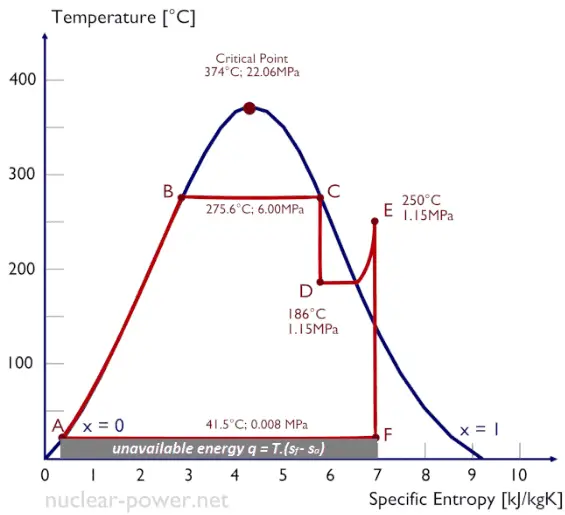
Temperature Entropy (T-s) Diagram A T-s diagram is the type of diagram most frequently used to analyze energy transfer system cycles. This is because the work done by or on the system and the heat added to or removed from the system can be visualized on the T-s diagram. The temperature-entropy diagram (Ts diagram) in which the thermodynamic state is specified by a point on a graph with specific entropy (s) as the horizontal axis and absolute temperature (T) as the vertical axis, is the best diagram to describe behaviour of a Carnot cycle. Answer (1 of 2): Area under a curve in a TS diagram represents heat transfer involved in the process. Q= shaded area under the process 1-2 Once you know the heat transfer involved in the system , apply first law of thermodynamics to find out the work transfer involved in the process. Q-... Acknowledgment.-The original entropy-temperature diagram for air, Fig. 1, was designed by the writer several years ago. Recently, Mr. John A. Dent, Instructor in Mechanical Engineering, simplified the construction of this chart and improved it by the addition of a series
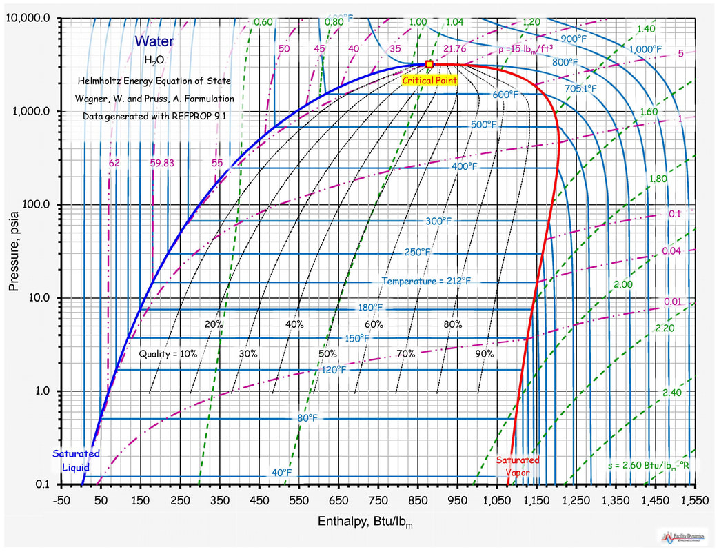
Aug 6, 2015. In some sense, yes. It's relatively straightforward. The entropy of a particular phase can be assumed to stay about the same within that phase (because the amount of rigidity is about the same). Typically, phase diagrams are pressure vs. temperature. If you keep the pressure constant, you can represent entropy, although indirectly. Temperature-Entropy Diagram. Recent Saturation Properties (max 20) - - Pressure Temperature Specific Enthalpy Specific Entropy Specific Volume; Saturated Liquid Evaporation Saturated Gas Saturated Liquid Evaporation Saturated Gas Saturated Liquid Evaporation Saturated Gas; psig °C: btu/lbm: kJ/kg/K: m³/kg-1.5: 96.9: 174.6: 973.6: 1,148.2: The most common type of pressure-enthalpy diagram is shown in Figures 1A through 1H. They show all five properties for a specific refrigerant in present-day use. Pressure is listed along the right and left borders in psia. Horizontal lines are constant pressure lines. Enthalpy is listed along the bottom and top of the diagram. The temperature entropy graph diagram of a reversible engine cycle is given in the figure Its efficiency is A dfrac14 B dfrac12 C dfrac23 D dfrac13
temperature vs. entropy diagram for febC. | Download ...
3. thermodynamics temperature-entropy (t-s) diagrama ts diagram is the type of diagram most frequently used to analyze energy transfer system cycles. this is because the work done by or on the system and the heat added to or removed from the system can be visualized on the t-s diagram. by the definition of entropy, the heat transferred to or …

| Temperature-entropy (T-s) diagram and composite curves ...
Temperature-entropy diagrams Fig.2 Temperature-entropy diagram of nitrogen. The red curve at the left is the melting curve. The red dome represents the two-phase region with the low-entropy side the saturated liquid and the high-entropy side the saturated gas. The black curves give the TS relation along isobars. The pressures are indicated in bar.

TEMPERATURE ENTROPY DIAGRAM FOR WATER SHOWING THE ...
The temperature diagram of a entropy reversible engine cycle is given in the figure, its efficiency is Hard View solution The temperature inside and outside a refrigerator are 273Kand 300K respectively. Assuming that the refrigerator cycle is reversible, for every joule of work done, the heat delivered to the surrounding will be nearly. Hard

Temperature-entropy diagram for different S-CO 2 Brayton ...
positive change in the entropy for the reaction. Construction of an Ellingham Diagram An Ellingham diagram is a plot of ∆G versus temperature. Since ∆H and ∆S are essentially constant with temperature unless a phase change occurs, the free energy versus temperature plot

Thermodynamic diagram temperature-entropy for twoshaft gas ...
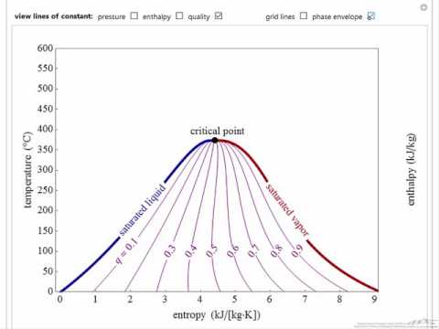
This Demonstration shows an enthalpy-entropy (-) diagram for water.Use the checkboxes to display lines of constant pressure (purple), temperature (green) or vapor quality (blue). Check "phase envelope" to show saturated liquid (magenta), saturated vapor (orange line) and the critical point (black dot).

white pasta on white paper
Enthalpy-Entropy Diagram Note : The current refrigerant R134a has a Global Warming Potential (GWP) of 1300 with respect to CO 2 . There is currently serious consideration of replacing it with R744 (Carbon Dioxide) in refrigeration and heat pump applications, as well as automotive air conditionong systems..

Temperature -Entropy diagram for different S-CO2 Brayton ...
The temperature-entropy diagram (Ts diagram) in which the thermodynamic state is specified by a point on a graph with specific entropy (s) as the horizontal axis and absolute temperature (T) as the vertical axis, is the best diagram to describe behaviour of a Carnot cycle.

Temperature-entropy diagram of IHGT cycle | Download ...
Temperature Entropy DiagramWatch more videos at https://www.tutorialspoint.com/videotutorials/index.htmLecture By: Er. Himanshu Vasishta, Tutorials Point Ind...

Simplified schematic representation of the entropy ...
T-S DIAGRAM=====Student's, if you face any problem then comment I'll try to solve as soon as p...

Thermodynamics thermal engineering entropy temperature ...
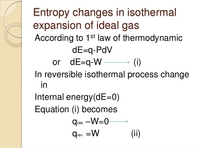
o The temperature is defined as that which is equal when heat ceases to flow between these samples. o Last time, we saw that entropy changes are related to heat transfer in reversible processes. The first law for a reversible process is: Lecture 4 - Temperature, heat, and entropy 4 of 12 9/15/05

gray rope on brown wooden table
A Temperature-entropy diagram ( T-s diagram) is the type of diagram most frequently used to analyze energy transfer system cycles. It is used in thermodynamics to visualize changes to temperature and specific entropy during a thermodynamic process or cycle.
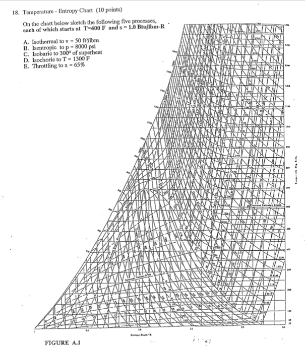
Temperature - Entropy Chart On The Chart Below Ske ...
1960] ENTROPY DIAGRAM 435 . Fi~ure . 4. Phase diagram. carbon dioxide: Entropy vs. Temperature vs. Pressure. CONCLUSION . It . is quite often difficult for a student of thermodynamics to estab lish a mental picture of what transpires during a thermodynamic process particularly during a phase change, since the data are usu

phase diagram (A) and Enthalpy-Pressure-Temperature ...
Temperature-entropy diagram of the ORC. The adiabatic expansion path 3-4 is replaced by the combination of the isentropic path 3-3s and the isobaric 3s-4. The mathematical model of the cycle was solved by using the EES [12] code which includes the thermodynamic properties of R152a. The computational results, including Θeq, the
white and gray thermostat at 19 5

Temperature Entropy Diagram for the Proposed System Layout ...
Entropy n process

Temperature -Specific Entropy -Diagram of the CH 4 /O 2 ...

white and yellow thermometer on white surface

Temperature-entropy diagram for chlorine | Download ...

TEMPERATURE ENTROPY DIAGRAM SHOWING THE DEPENDENCY OF THE ...

Temperature-entropy diagram of the R125 in the heat ...

Ethanol Phase Diagram — UNTPIKAPPS

Temperature-entropy diagram of CO 2 condensation process ...
Thermodynamics Glossary - Temperature-Entropy Diagram

TEMPERATURE ENTROPY DIAGRAM FOR WATER - Mechanical ...
What is Temperature-entropy Diagram - T-s Diagrams ...

white and black rope on brown wooden table
temperature entropy diagram | Download Scientific Diagram

Temperature-entropy diagram for Types (e) and (f); working ...

Temperature-entropy diagram of the binary cycle which uses ...
Temperature-Entropy Diagram (Interactive Simulation) - YouTube
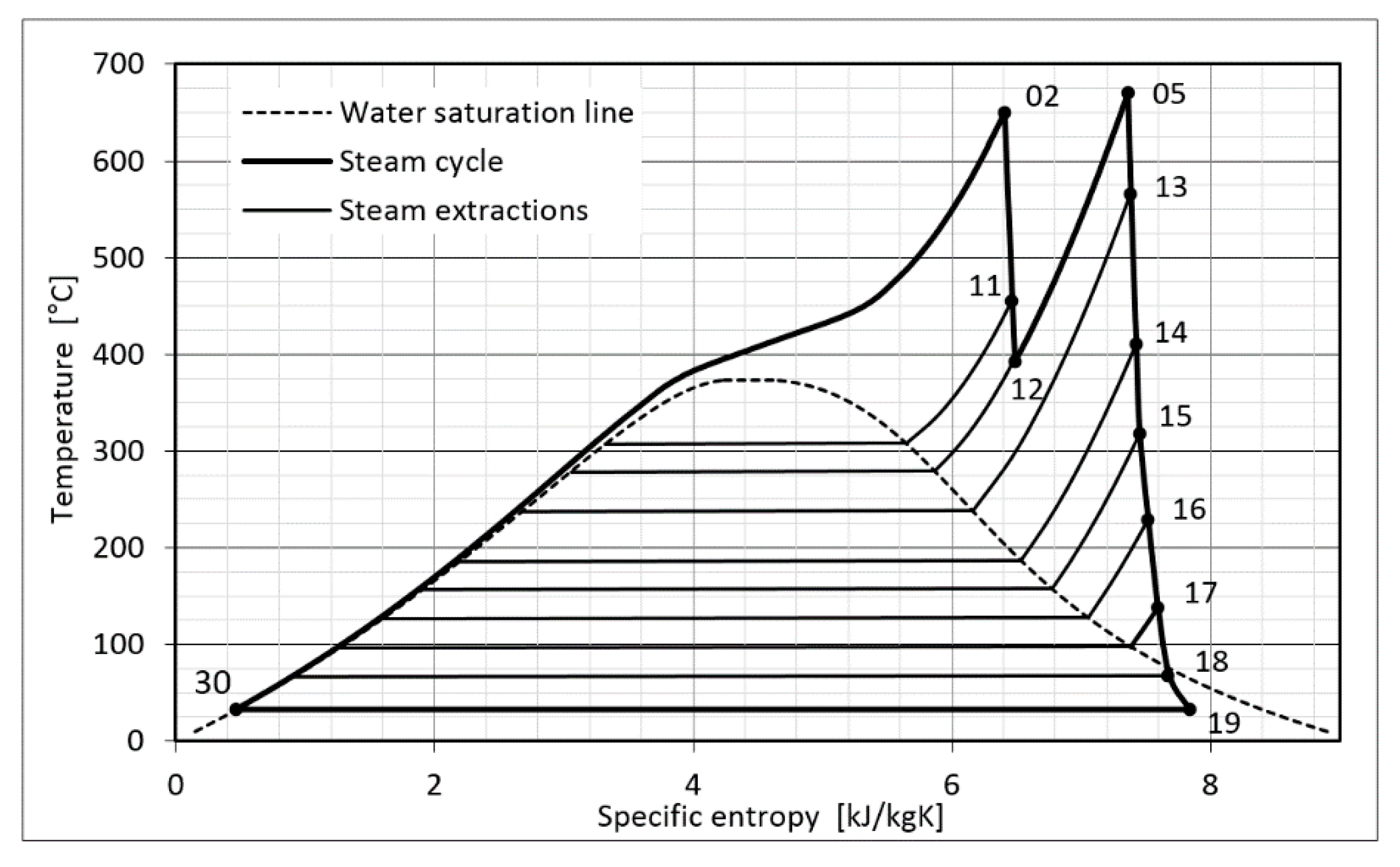
Temperature-entropy diagram for steam turbine plant ...

Temperature-entropy diagram for an ideal loss-free process ...

person in teal long sleeve shirt lying on bed

Temperature Entropy diagram for R410a | Download ...
Temperature-entropy diagram for natural gas for various ...
Entropy | Free Full-Text | Exergy Losses in the Szewalski ...

Temperature-entropy diagram for H 2 O. S = solid (ice), L ...

Temperature-Entropy diagram of a double flash power plant ...

Temperature-entropy diagram of a USC cycle with reheat ...
Thermodynamic Diagrams Spreadsheet

Entropy-temperature diagram for miniature ADR cycle ...


Comments
Post a Comment