42 fire pump diagram
Fire pump is a part of a fire sprinkler system's water supply and powered by electric, diesel or steam. The pump intake is either connected to the public und... Description: Fire And Jockey Pump Controller Sensing Lines | Mike Trumbature with regard to Fire Pump Wiring Diagram, image size 797 X 612 px, and to view image details please click the image.. Here is a picture gallery about fire pump wiring diagram complete with the description of the image, please find the image you need.
Pinterest Lite. Save space on your device. Download. Visit. Save. Fire Pump Wiring Diagram Big Dog Motorcycle, Motorcycle Wiring, Land Rover Defender, Ford.

Fire pump diagram
Figure 3: A general fire pump room schematic layout diagram is shown. Courtesy: WSP USA. Sizing a fire pump. A fire pump is designed to handle the most demanding fire sprinkler system. In a typical building like a high-rise office, there is the sprinkler demand on each floor, along with the standpipe. Other types of buildings may have a foam ... FIRE PUMP CONTROLLER WIRING DIAGRAM · Connector JA (6 Poles) Mains Voltage Inputs · Connector JB: (5 Poles) NPN Short Circuit Proof Static Auxiliary Outputs. Here’s a 3-phase example. A 25-hp, 208V 3-phase fire pump motor is 175 ft from the service. The fire pump motor controller is 150 ft from the service. What size conductor must you install to the fire pump motor controller? Terminals are rated 75ºC. The answer: 3 AWG THHN. See Figure 695-2 un695-02 695-07 01.cdr
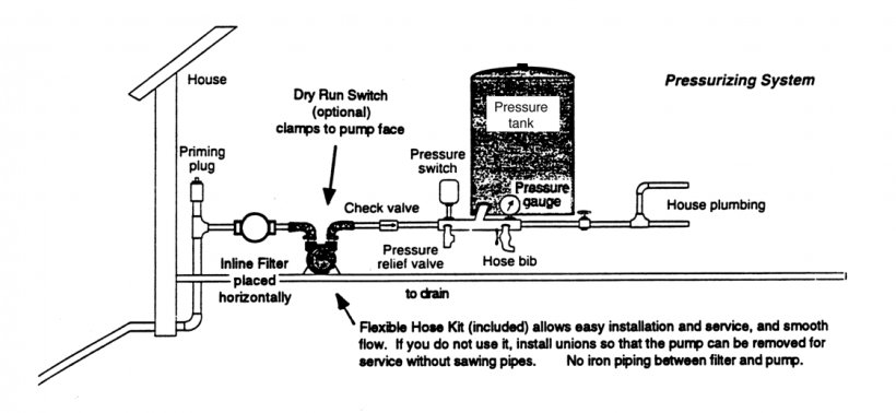
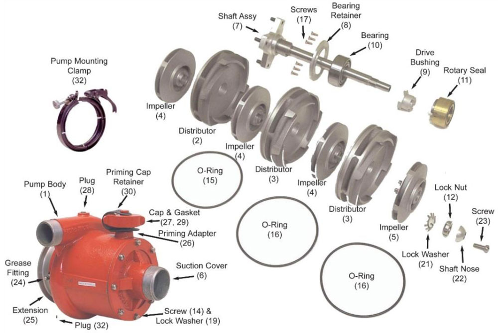
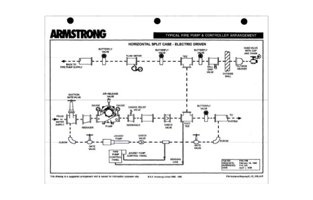
Fire pump diagram. A fire pump is a device that provides the required water flow and pressure for a fire protection system. The fire pump unit itself consists of a pump, a drive, a driver coupling connecting the two, and a base plate. Fire pumps are normally purchased as a complete package that includes the following: Pump accessories (electric drive): Including ... Waterous Fire Pump Diagram. 16.10.2018. 16.10.2018. 6 Comments. on Waterous Fire Pump Diagram. Warranty information contains the Conditional Warranty for Waterous Pumps. •. Instructions ous fire pump, transmission or power take−off. “Printed” service parts lists show exploded diagrams of a particular assembly along with part. 16 Jul 2021 — Zoomlian Pump analyzes the installation method of the vertical pipeline fire pump and provides the installation diagram for reference only. The Fire Pump Flow Test Nfpa 25 Annual Tests. Ul fm fire pump controller for electric controllers eaton sel check list jockey tornatech pumps and firepaks installation manual engine reservoir under firewater system an overview float switch wiring instruction bulletin fta1100j markiii legacy product sve motor driven the flow test nfpa 25 annual ft0f firetrol a guide to on ship integrated ...
6 Aug 2013 — A fire pumps is made up of three major parts: the speed increaser/pump transmission, the impeller shaft assembly, and the pump body. All play ... • If the fire pump are electric driven fire pumps, power supply need to be sustained or at least one fire pump need to be diesel engine fire pump. • Jokey pump is used to solve the issue of small pressure drops in the fire installation before the main fire pumps are activated; its flow rate must be min. 1/100 of the flow rate of the main ... Fire Engine Pump and Plumbing Diagram This basic diagram was designed to help you understand the functionalty of a fire engine's pump and plumbing. Every fire engine's plumbing is build differently. Keep in mind that your fire engine's pump and plumbing will have a different configuration and may not be equiped with all the valves listed. Fire Apparatus Pump Operations, Mechanics, and Components Plain Water Operations Centrifugal Pumps Fire apparatus pumps use centrifugal force to deliver water to the fireground. Centrifugal force is an outward force associated with rotation. The rotation in a fire apparatus pump is powered
(Refer to terminal diagram for terminal sizes.) The electrical wiring between the fire pump controller and the pump motor shall be in rigid, intermediate, or ...17 pages Here’s a 3-phase example. A 25-hp, 208V 3-phase fire pump motor is 175 ft from the service. The fire pump motor controller is 150 ft from the service. What size conductor must you install to the fire pump motor controller? Terminals are rated 75ºC. The answer: 3 AWG THHN. See Figure 695-2 un695-02 695-07 01.cdr FIRE PUMP CONTROLLER WIRING DIAGRAM · Connector JA (6 Poles) Mains Voltage Inputs · Connector JB: (5 Poles) NPN Short Circuit Proof Static Auxiliary Outputs. Figure 3: A general fire pump room schematic layout diagram is shown. Courtesy: WSP USA. Sizing a fire pump. A fire pump is designed to handle the most demanding fire sprinkler system. In a typical building like a high-rise office, there is the sprinkler demand on each floor, along with the standpipe. Other types of buildings may have a foam ...

PPT - Fire Pump Theory PowerPoint Presentation - ID:1159597

Tampa Baseball Outreach - SCORE International
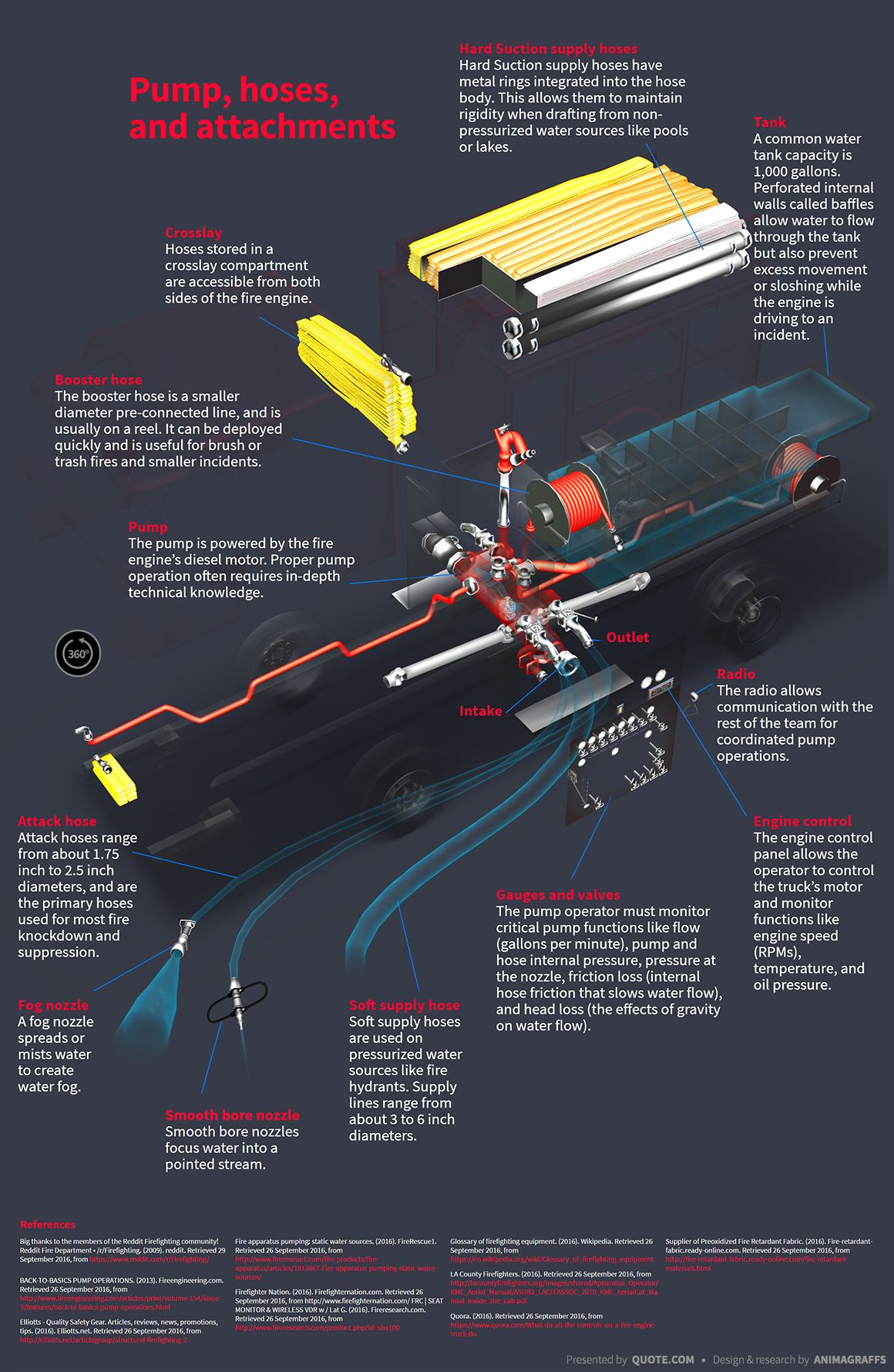
How Fire Engines Work | quote.com

Waterous Fire Pump Diagram

Monochrome, Colonnaded Architecture, Royal Naval College, Greenwich, London, England.

Patent US7987916 - Integrated controls for a fire ...

Waterous Fire Pump Diagram
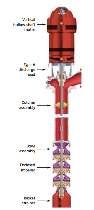
Vertical Turbine Pumps | AC Fire Pump

Fire Pump Systems : simplebooklet.com

Waterous Fire Pump Diagram

Jet D'eau, Tallest Water Fountain In The World, Lake Geneva, Geneva, Swiss Confederation.

Burning dandelion

Fiery silhouette

Fire on the Horizon
أرض صاØب خامسا fire pump wiring diagram - psidiagnosticins.com
![[DIAGRAM] Wiring Diagram Panel Pompa Hydrant FULL Version ...](https://allpumps.com.au/wp-content/uploads/2018/04/diesel-fire-hydrant-drawing-side.png)
[DIAGRAM] Wiring Diagram Panel Pompa Hydrant FULL Version ...

Fire 259

“Oh, I can make that fire big.†- My father

ANVIL FIRE - Pump Sizing App

Fire Pump Wiring Diagram - Wiring Diagram And Schematic ...

A schematic explaining the heat engine invented by Savery ...

Engineer: Fire Pump Design Calculate (à¸à¸²à¸£à¸„ำนวณà¹à¸¥à¸°à¸à¸²à¸£à¸à¸à¸à¹à¸šà¸š ...

Monochrome, Dounreay Nuclear Establishments, Caithness, Highlands, Scotland.

Elektische Ausrüstung—- Electrical installation

Engine Wiring Diagram For A 3412 Fire Pump Engine

Фото Ивана МиÑко и Олега Ðовицкого на Международной коÑмичеÑкой Ñтанции. Photo by Ivan Misko and Oleg Novitskiy at the International Space Station.

Fire Pump Controller Wiring Diagram | Free Wiring Diagram

Pump Room - Startech Fire Systems

The Pumps Blog: Patterson Pumps

29 Fire Pump Installation Diagram - Wiring Database 2020
Mercedes Textiles - WICK® FSP4200 4-Stage Pump Parts ...

NIF Laser Bay one of two.

Waterous Fire Pump Diagram
Jayco Pop Up Camper Lift System Diagram

ROC NO.1 Group Headquarters, 57 London Road, Maidstone
![[DIAGRAM] Wiring Diagram Jockey Pump FULL Version HD ...](http://svpump.com/wp-content/uploads/2012/10/firepump-INSTALLATION.jpg)
[DIAGRAM] Wiring Diagram Jockey Pump FULL Version HD ...
Nfpa20 standard for the installation of stationary pumps ...

Burning firewood

3 tips for Fire Pump maintenance | Pumps Africa

Fire Pump Wiring Diagram - Wiring Diagram And Schematic ...

Fire Pump Controller Wiring Diagram | Free Wiring Diagram

Figure 1 from Reliability Analysis for Power to Fire Pump ...


Comments
Post a Comment