42 how to wire a shunt trip breaker wiring diagram
Nov 04, 2018 · 5 way trailer wiring diagram; 5 wire 4 pin trailer wiring diagram; 5 wire flat trailer wiring diagram; 5 wire strobe light wiring diagram; 5 wire trailer light diagram; 5 wire trailer wiring diagram; 5 wire trailer wiring diagram nz; 5 wire trailer wiring diagram troubleshooting; 5.3 truck alternator wiring diagram; 5.3 vortec engine diagram Aug 13, 2020 — Shunt trip coil is energized only for a short time, over time to burn; so in the control loop in the normally closed contacts connected in ...
Mar 13, 2019 — Shunt trip breaker wiring diagram, This post is about the single wiring diagram of MCCB shunt trip breaker. In the diagram an MCCB (molded ...

How to wire a shunt trip breaker wiring diagram
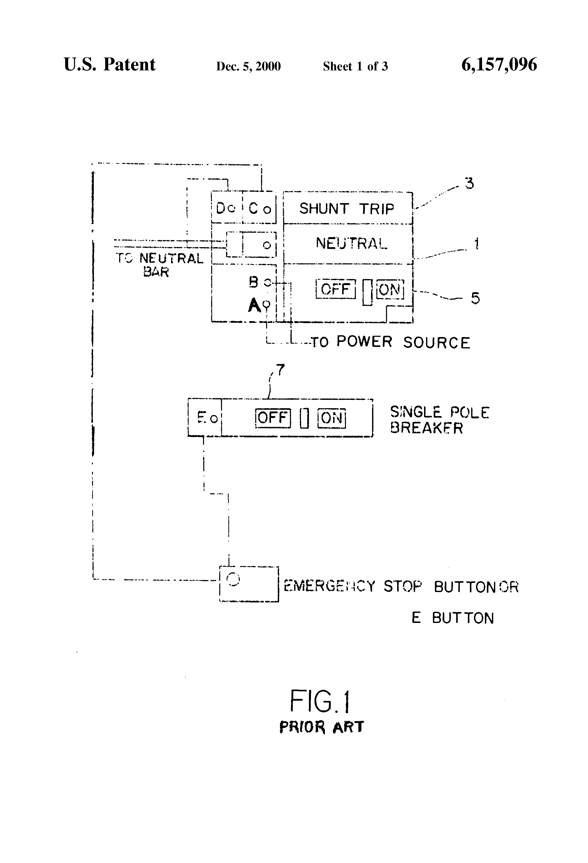
Resolution: Connect the appropriate voltage (ie. 120V to 240V for the -1021 suffix) to the two terminals on the shunt trip. Land the switch leg ... Aug 1, 2021 — 1. Connect the neutral wire of the power supply to anyone terminal of the shunt trip coil. · 2. Connect any one terminal of the EPO button to any ... Apr 25, 2017 — Wire one of the fuses out to a terminal. Wire the other fuse to one side of the shunt trip and one side of the breaker auxiliary contact, which ...
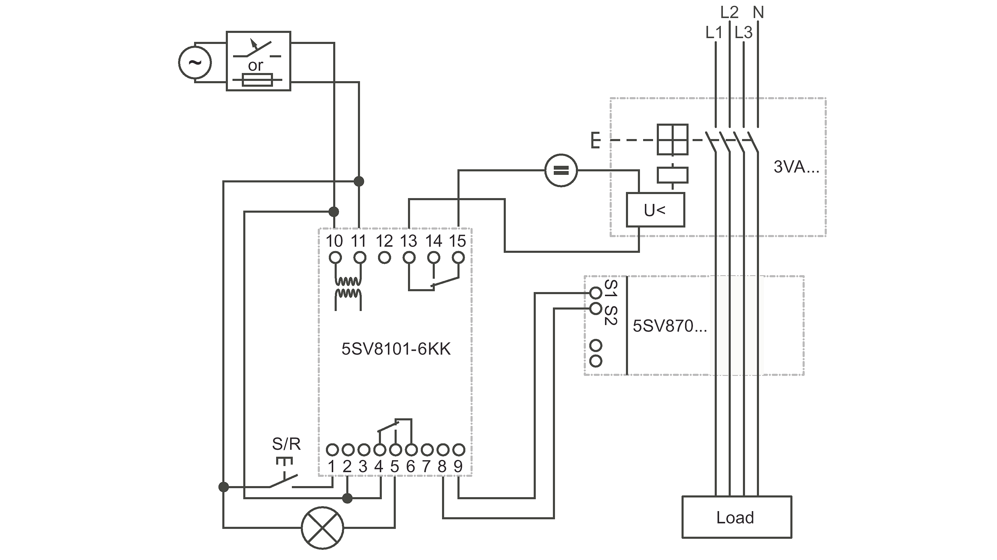
How to wire a shunt trip breaker wiring diagram. Nov 26, 2021 · Wiring Diagram Pics Detail. 1 A shunt trip breaker is a breaker with a solenoid to trip when power is applied to the solenoid. 6 Install circuit breaker. This is a very simple wiring diagram. Shunt breaker wiring diagram Wiring Diagram for Shunt Trip Breaker Copy Best Shunt Trip Breaker Wiring Diagram 71 for Chromalox Heater. Jul 22, 2018 · 3 wire solenoid valve wiring diagram; 3 wire strobe light wiring diagram; 3 wire thermistor wiring diagram; 3 wire thermocouple wiring diagram; 3 wire throttle position sensor wiring diagram; 3 wire trailer light diagram; 3 wire trailer light wiring diagram; 30 amp rv transfer switch wiring diagram; 30 amp single pole circuit breaker wiring diagram Mar 24, 2015 · Elevator Shunt Trip is a function that involves the fire alarm system via heat detectors, shunting the breaker that controls the elevator equipment (typically set to activate 5 degrees before the actual automatic sprinkler head pops.). This in turn powers down the elevator equipment before any automatic sprinkler water is released. 3VA61 150A Electronic Trip Circuit Breakers 5-35 – 5-38 3VA52 250A Thermal-magnetic Trip Circuit Breakers 5-39 – 5-42 3VA62 250A Electronic Trip Circuit Breakers 5-43 – 5-46 3VA53 400A Thermal-magnetic Trip Circuit Breakers 5-47 – 5-48 3VA63 400A Electronic Trip Circuit Breakers 5-49 – 5-52
Dec 22, 2017 · K Frame Shunt Trip. Circuit breaker shunt trip on a edb br120st eaton type br brkr 20a 1 pole square d qou2601021 province electric the t80 wiring diagram 31 motor mechanism siemens miniature amps thermal magnetic 3 200 amp 240 vac madcomics how to install breakers b12000s01 ch120st 1p i am an ansul fire suppression china release sht for abb s5n second life k frame mcb accessories q and m two ... Installation Instructions for Low Energy Shunt Trip for. EHD, FDB, FD, HFD, FDC, FW, HFW, FWC Circuit Breakers,. Molded Case Switches, and Motor Circuit ...8 pages This book contains examples of control circuits, motor starting switches, and wiring diagrams for ac manual starters, drum switches, starters, contactors, … Jul 12, 2019 · Size: 65.72 KB. Dimension: 1594 x 696. DOWNLOAD. Wiring Diagram Pics Detail: Name: shunt breaker wiring diagram – Wiring Diagram for Shunt Trip Breaker Copy Best Shunt Trip Breaker Wiring Diagram 71 for Chromalox Heater. File Type: JPG. Source: irelandnews.co. Size: 453.05 KB. Dimension: 2320 x 3408.
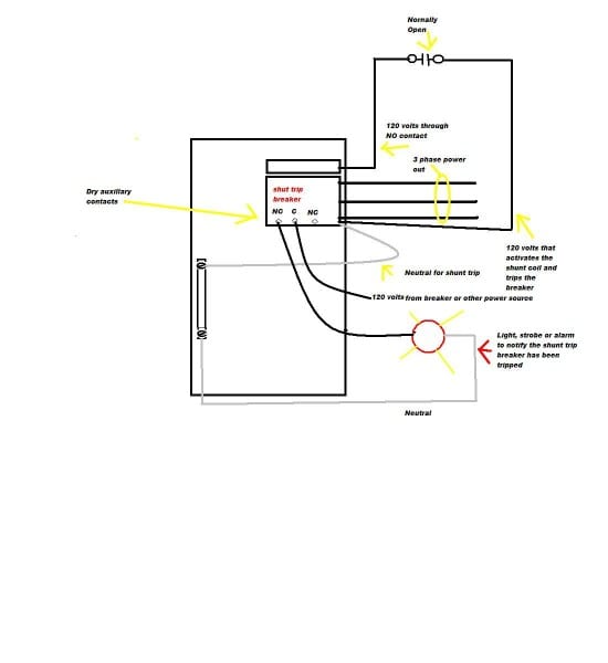
Mar 14, 2007 — Product Line:Circuit BreakersQOEnvironment:Electrical Distribution EquipmentResolution:Connect the appropriate voltage (ie. 120V to 240V for ... ELR Wiring diagram . A typical wiring diagram of an earth leakage relay is shown below. Operational power is applied to the terminal A 1 and A 2 of the ELR and the CBCT is connected to the terminals T 1 and T 2. The normally closed terminals of the fault signalling contacts are connected to the Undervoltage release coil of the circuit breaker. Dec 17, 2021 · The busbar itself as well as the shunt for the battery monitor and fuse mounted inside to the busbar protecting the positive wire from overcurrent can be found in this section. The busbar is essentially an extension of the battery terminals and allows you to deliver power where it needs to go and houses the fuses necessary to protect the wires ... Oct 28, 2016 · To wire a shunt tripping breaker follow the below steps. First of all wire your Circuit breaker. Then connect the neutral wire to shunt trip coil. Then connect the Phase (hot wire) to the EPO button normally open contact. Then get connection form EPO other side of normally open contact and connect to the shunt trip coil.
Siemens Shunt Trip Breaker Wiring Diagram
Jul 27, 2021 · Meanwhile, the shunt trip breaker wiring comprises two wires. One connected to the ground, and another to a control system. The control system can be connected to a sensor or to a manual switch. When activated, the shunt trip accessory will cause the main breaker to trip.

Siemens Shunt Trip Breaker Wiring Diagram Sample | Wiring ...
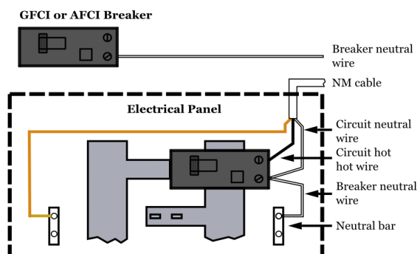
Apr 09, 2021 · House Wiring Diagram Wire Shunt Trip Breaker Diagramwire. How To Install Trip Breakers. The Common Wire On Normally Open And Closed Contacts Of A Shunt Trip Breaker Should Be My Neutral. Square D Qob250 1021 2 Pole 50 Amp W Shunt Trip Com. Square D Kal36200 W Shunt Trip Circuit Breaker. Square D Miniature Circuit Breaker Amps 30 A Type Shunt ...

Find Out Here Fire Alarm Elevator Recall Wiring Diagram Sample
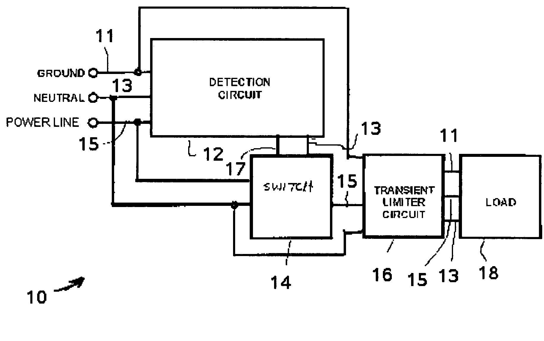
MicroLogic trip systems use a set of current transformers (called CTs or sensors) to sense current, a trip unit to evaluate the current, and a tripping solenoid to trip the circuit breaker. Adjustable rotary switches on the trip unit allow the user to set the proper overcurrent or equipment ground-fault current protection required in the ...

Sea
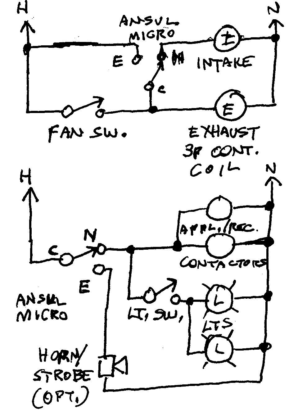
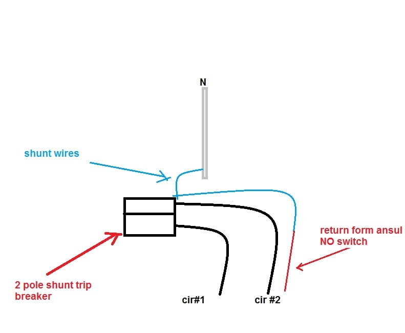
Apr 06, 2019 · How to wire for a fire suppression system. OK let's proceed. 1) A shunt trip breaker is a breaker with a solenoid to trip when power is applied to the solenoid. A micro switch, usually provided by the Ansel Installers, has a NO / NC contacts. Your circuit (15A) for tripping the shunt breaker can originate in the same panel. 2).
Square D Shunt Trip Breaker Wiring Diagram
Oct 21, 2009 — A shunt-trip on a breaker is just a breaker that contains a remote-control way of tripping it. Sending 120v to the coil trips it, and then it ...Shunt Trip Breaker Wiring | Mike Holt's ForumOct 7, 2015Shunt-trip breaker - help with connectionsMar 12, 2007Kitchen hood - shunt trip breakers required. | Mike Holt's ForumApr 17, 2012wiring shunt trip breakers | Mike Holt's ForumAug 25, 2005More results from forums.mikeholt.com
Cutler Hammer Shunt Trip Breaker Wiring Diagram
Apr 25, 2017 — Wire one of the fuses out to a terminal. Wire the other fuse to one side of the shunt trip and one side of the breaker auxiliary contact, which ...

Ge Shunt Trip Breaker Wiring Diagram
Aug 1, 2021 — 1. Connect the neutral wire of the power supply to anyone terminal of the shunt trip coil. · 2. Connect any one terminal of the EPO button to any ...

Secret Diagram: Get Circuit diagram symbols circuit breakers
Resolution: Connect the appropriate voltage (ie. 120V to 240V for the -1021 suffix) to the two terminals on the shunt trip. Land the switch leg ...

Shunt Trip Wiring Diagram - Wiring Diagram And Schematic ...

Ge Shunt Trip Breaker Wiring Diagram | Free Wiring Diagram

Shunt Trip Wiring Diagram For Elevator - Wiring Diagram

Shunt Breaker Wiring Diagram - Wiring Diagram And ...

120V Shunt Trip Breaker Wiring Diagram Database
Shunt Trip Breaker Wiring Diagram | Wiring Diagram

Shunt Trip Circuit Breaker Wiring Diagram - Wiring Diagram ...

Shunt Trip Breaker Wiring Diagram - Wiring Diagram

Shunt Trip Breaker Wiring Diagram - Diagram Stream

Shunt Trip Breaker Wiring Diagram - Diagram Stream

Cutler Hammer Shunt Trip Breaker Wiring Diagram | Free ...

Shunt Trip Breaker Wiring Diagram - Wiring Diagram ...

Shunt Trip Breaker Wiring Diagram - Free Wiring Diagram

Ge Shunt Trip Breaker Wiring Diagram Collection

Shunt Trip Wiring Diagram - Wiring Diagram And Schematic ...

Shunt Trip Wiring Diagram Eaton - Wiring Diagram

Shunt Trip Wiring Diagram For A Siemens Ed4 Breaker
Shunt Trip Circuit Breaker Wiring Diagram

Shunt Trip Circuit Breaker Wiring Diagram - Wiring Diagram ...

Ge Shunt Trip Breaker Wiring Diagram | Free Wiring Diagram

Wiring Diagram: 32 How To Wire A Shunt Trip Breaker Wiring ...

Fire Alarm Elevator Recall Wiring Diagram Gallery

Ge Shunt Trip Breaker Wiring Diagram | Free Wiring Diagram

Shunt Trip Breaker Wiring Diagram | Free Wiring Diagram

Sticking feet out car window
Shunt Breaker Wiring Diagram Gallery - Wiring Diagram Sample
120v Shunt Trip Breaker Wiring Diagram With Control ...
How To Wire A Shunt Trip Breaker

Shunt Trip Breaker Wiring Diagram - Diagram Stream

Single Pole Shunt Trip Breaker Wiring Diagram Collection

Siemens Shunt Trip Breaker Wiring Diagram Gallery

Square D Shunt Trip Breaker Wiring Diagram - Complete ...
Auxilary Breaker c/w Shunt trip - TM-5-3895-374-24-1_130

Square D Shunt Trip Circuit Breaker Wiring Diagram ...


Comments
Post a Comment