42 iron carbon ttt diagram
In this chapter, the two types of TIT diagrams used are described and the methods of determining them are outlined. These diagrams are affected by the carbon and alloy content and by the prior austenite grain size, and the way in which these factors affect them is examined. ANS.:- From TTT diagrams below 1- Austenite transform to 100% bainite . 2- Austenite transform to 50% bainite and 50% perlite . Example (2) Using the isothermal transformation diagram for an iron-carbon alloy of eutectoid composition, specify the nature of the final microstructure of a
Answer to Using the T-T-T diagram for an iron-carbon alloy of eutectoid composition shown in figure below, specify the nature of t...

Iron carbon ttt diagram
1) Equilibrium phase diagrams, Particle strengthening by precipitation and precipitation reactions 2) Kinetics of nucleation and growth 3) The iron-carbon system, phase transformations 4) Transformation rate effects and TTT diagrams, Microstructure and property changes in iron-carbon system Contents Oct 11, 2017 · IRON CARBON EQUILIBRIUM DIAGRAM, TTT DIAGRAM AND HEAT TREATMENT 1. IRON CARBIDE DIAGRAM TTT DIAGRAM & HEAT TREATMENT By: Ankit Saxena 2. IRON-C phase diagram 3. From previous fig of FE-C diagram 4. • Hypo-eutectoid steels: Steels having less than 0.8% carbon are called hypo-eutectoid steels (hypo means "less than"). , with carbon concentrations up to a few percent you need to worry. Graphite might form, depending on conditions. For ... , the usual thing nowadays, you need to worry, too. Some alloying elements, in particular silicon (Si) but also nickel (Ni), promote graphite formation. ... TTT Diagrams: 1.
Iron carbon ttt diagram. The iron-carbon diagram Learning objectives: - You name and describe the different phases of pure iron during the cooling process. Factors affecting TTT diagram Composition of steel- (a) carbon wt%, (b) alloying element wt% Grain size of austenite Heterogeneity of austenite Carbon wt%- As the carbon percentage increases A3 decreases, similar IS the case for A i.e. austenite stabilises. So the incubation period for the Simply because there will be pathways ... to keep the TTT diagrams a bit "open", hoping that the user knows how to deal with it. We will see a bit better how this works in the next examples. Shown are actual and somewhat more involved diagrams for 0.44 % carbon steel... The Iron-Iron Carbide (Fe-Fe3C) Phase Diagram In their simplest form, steels are alloys of Iron (Fe) and Carbon (C). The Fe-C phase diagram is a fairly complex one, but we will only consider the steel part of the diagram, up to around 7% Carbon.
Iron –Iron-carbon diagrams provides the best medium to understand this aspect. The diagram provides the foundation knowledge on both plain carbon and alloy steels in a great variety. It must be noted that the normal equilibrium diagram actually is a metastable equilibrium diagram between iron and iron carbide (cementite). TTT diagram of isothermal transformations of a hypoeutectoid carbon steel; showing the main components obtained when cooling the steel and its relation with the Fe-C phase diagram of carbon steels. Therefore TTT diagram consists of different isopercentage lines of which 1%, 50% and 99% transformation lines are shown in the diagram. At high temperature while underlooling is low form coarse pearlite. At the nose temperature fine pearlite and upper bainite form simultaneously though the mechanisms of their formation are entirely different. April 13, 2020 - Official Website: Information about programs offered, departments, activities, research, consultancy, admissions, events, and contacts.
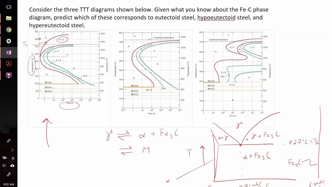
The CCT diagram (solid lines) for a 1080 steel compared with the TTT diagram (dashed lines). 67. ©2003 Brooks/Cole, a division of Thomson Learning, Inc. Thomson Learning ™ is a trademark used herein under license. (a)TTT and (b) (b) CCT curves for a 4340 steel. 68. Factors Affecting TTT Diagram • 1. Grain size • 2. Carbon content • 3. Example problem and solution showing how to match TTT diagram to eutectoid, hypoeutectoid, and hypereutectoid steel compositions. ttt diagram is a plot of temperature versus the logarithm of time for a steel alloy of the complete isothermal transformation diagram for an iron-carbon alloy.c metastable equilibrium diagram and ttt diagrams for plain carbon hypoeutectoid, eutectoid and hypereutectoid steels m s (a) fe-fe 3 c metastable phase diagram (b) ttt diagram for … Somewhere on your IRON -carbon diagram is the word "equilibrium" ; It describes equilibrium conditions. TTT curves are sort of the antithesis of equilibrium ; The right hand boundary is static conditions. But the route or path taken to get to the right boundary makes a substantial difference in what you have when you get there .
Carbon and Carbide Building, Chicago, Illinois, Perspective Sketch (1927–28) // Burnham Brothers (American, 1924-1929) Daniel Hudson Burnham, Jr. (American, 1886-1961) Hubert Burnham (American, 1882-1968)
2. TTT - Diagrams 13 Different carbon solubility of solid solutions also results from lattice structures. The three a-bove mentioned phases dissolve carbon interstitially, i.e. carbon is embedded between the iron atoms. Therefore, this types of solid solutions are also named interstitial solid solution.
TTT diagram
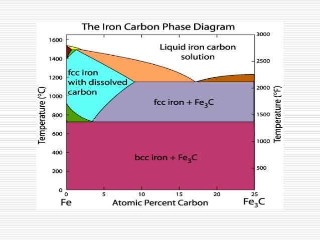
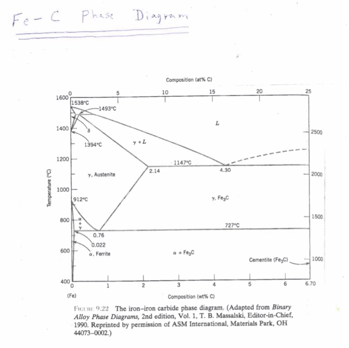
What is the iron carbon equilibrium diagram? The part of iron-carbon alloy system diagram between pure iron and an interstitial compound, iron carbide (Fe3C), containing 6.67 percent carbon by weight is called iron-iron carbide equilibrium diagram. In fact, the compound iron carbide decomposes into iron and carbon (graphite).
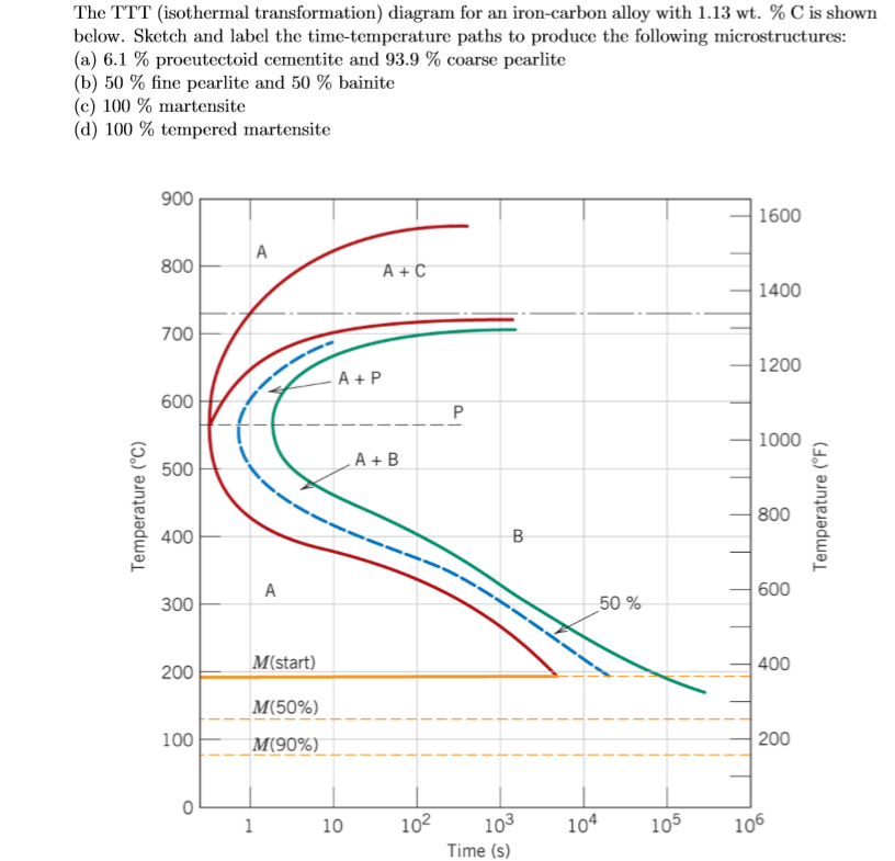
Solved: The TTT (isothermal Transformation) Diagram For An ...
Iron Carbon Ttt Diagram TTT diagram is a plot of temperature versus the logarithm of time for a steel alloy of The complete isothermal transformation diagram for an iron-carbon alloy. Imagine, for example, some pure iron that was kept at a temperature of oC ( .. Here is the "official" isothermal TTT diagram for eutectoid carbon steel.
Solved: B) TTT Diagram 2) Using The Isothermal Transformat ...
Phase diagram for the binary system iron-carbon (Fe-C). General construction The phase composition depending on the temperature and the carbon content can be read off this dual diagram in which the stable system iron-graphite (dotted lines) and the meta-stable system iron-carbide (solid lines) ...
Ttt Diagram Explanation Pdf - Diagram
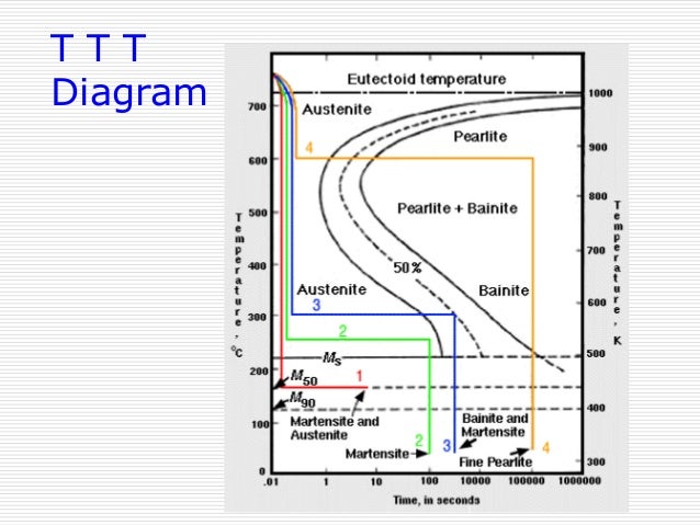
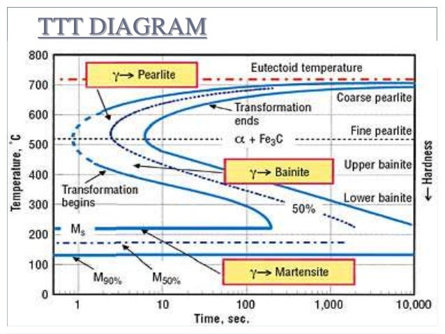
TTT diagram indicates when a specific transformation starts and ends and it also shows what percentage of transformation of austenite at a particular temperature is achieved. Look at figure 1b and 1c. Figure 2. Upper half of TTT Diagram(Austenite-Pearlite Transformation Area) Figure 2 represents the upper half of the TTT diagram.
Below is the Time-Temperature-Transformation (TTT) | Chegg.com
Transcribed image text: b. Use the TTT diagram for a 0.45 wt% C iron-carbon alloy below, to design a a heat treatment that could be used to isothermally convert a microstructure that consists of proeutectoid ferrite and fine pearlite into one that is composed of proeutectoid ferrite and bainite?

Fe-Carbon Diagram, TTT Diagram & Heat Treatment Processes ...
Time-temperature-transformation (TTT) diagram

unknown
Download scientific diagram | Iron-Carbon Phase diagram [12] from publication: Sliding Wear Behavior of Self-Mated Carbide-free Bainitic Steels | In this ...

Sparky's Sword Science: Alloys, Microstructures and Phase ...
Cementite or iron carbide, is very hard, brittle intermetallic compound of iron & carbon, as Fe 3 C, contains 6.67 % C. It is the hardest structure that appears on the diagram, exact melting point unknown. Its crystal structure is orthorhombic. It is has low tensile strength (approx. 5,000 psi), but high compressive strength.
Examples of Iron-Iron Carbide Transformations
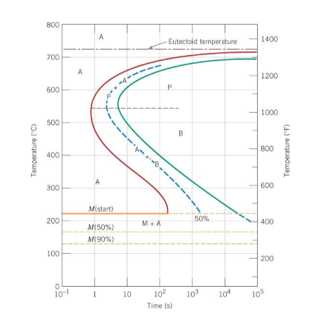
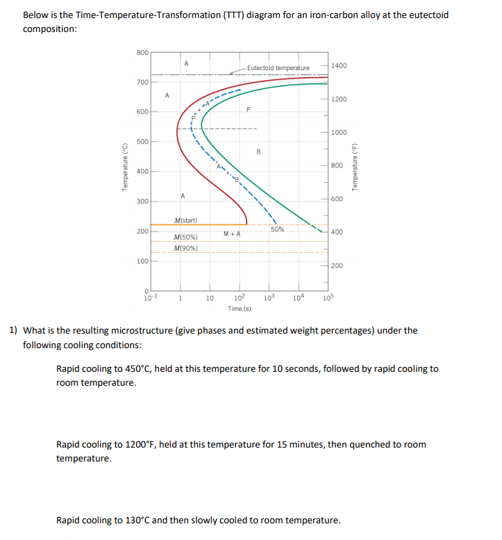
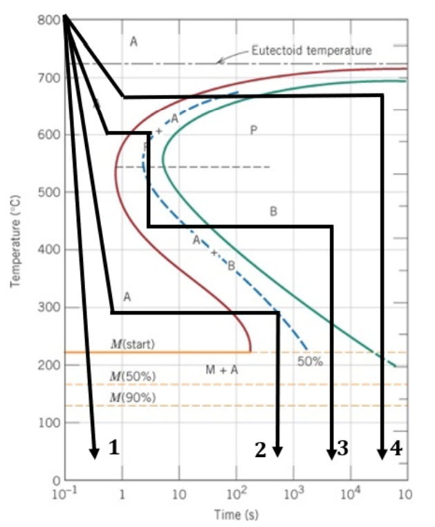
The complete TTT diagram for an iron-carbon alloy of eutectoid composition. A: austenite B: bainite M: martensite P: pearlite Er. Saurabh Malpotra . TTT Diagram Transformations at temperatures between approximately 705°C and 550°C result in the characteristic lamellar microstructure of pearlite.
IRON CARBON EQUILIBRIUM DIAGRAM, TTT DIAGRAM AND HEAT ...
A TTT (Time-Temperature-Transformation) diagram is extensively used in the assessment of decomposition of austenite in heat-treatable steels. As the iron-carbon diagram reveals the phases and their microstructures under equilibrium conditions and does not show time as a variable so the effect of different cooling rates on the structure of steel ...

Cleveland Punch and Die Company Blog Page: Tooling ...
Ttt or itt diagrams iron carbon fe c phase diagram. This preview shows page 17 - 28 out of 66 pages. • Eutectoid composition, C o = 0.76 wt% C • Begin at T > 727° C • Rapidly cool to 625° C and hold isothermally. Effect of Cooling History in Fe-C System 400 500 600 700 Austenite (stable) T E (727 C) Austenite (unstable ) Pearlite T (°C ...

Iron Phase Diagram
Enjoy the videos and music you love, upload original content, and share it all with friends, family, and the world on YouTube.
IRON CARBON EQUILIBRIUM DIAGRAM, TTT DIAGRAM AND HEAT ...
June 1, 2012 - Dr. Dmitri Kopeliovich Iron-carbon phase diagram describes the iron-carbon system of alloys containing up to 6.67% of carbon, discloses the phases compositions and their transformations occurring with the alloys during their cooling or heating.

Articulated Dragon (c. 1880) // Myochin School Japanese, active late 19th century
asked Dec 29, 2017 in material science by chandu (215k points) Which one of the following statements is correct? (a) Iron-carbon and TTT diagrams are both equilibrium diagrams. (b) Iron-carbon and TTT diagrams are both non-equilibrium diagrams. (c) Iron-carbon diagram is an equilibrium diagram but TTT diagram is a non-equilibrium diagram.
Iron Carbon Phase Diagram
10.18 Using the isothermal transformation diagram for an iron-carbon alloy of eutectoid composition (Figure 10.22), specify the nature of the final microstructure (in terms of microconstituents present and approximate percentages of each) of a small specimen that has been subjected to the following time-temperature treatments. In

Armor for Field and Tournament (c. 1540/60 with later etching) // Jörg T. Sorg, the Younger, after German, Augsburg, active 1502-1542
The effect of time-temperature on the microstructure changes of steel can be shown by the TTT diagram. These diagrams are extensively used in the assessment of the decomposition of austenite in heat-treatable steels. We have seen that the iron-carbon phase diagram does not show time as a variable and hence the effects of different cooling rates ...

people sitting at the table
APPLICATIONS OF Fe-C. PHASE DIAGRAM ... Excess carbon is in the form of iron carbide ... When molten cast iron solidifies some of the carbon.
IRON CARBON EQUILIBRIUM DIAGRAM, TTT DIAGRAM AND HEAT ...
The iron-carbon diagram and TTT curves are determined under? A. Equilibrium and non equilibrium conditions respectively B. Non-equilibrium and equilibrium conditions respectively C. Equilibrium conditions both D. Non-equilibrium conditions both Answer: Option A
TTT Diagram
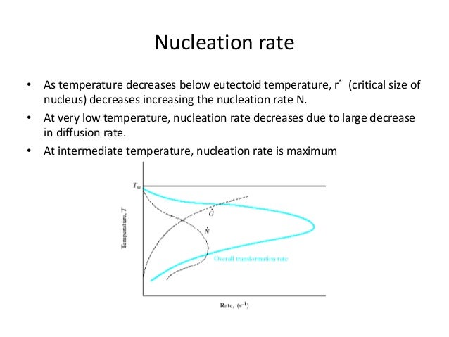
October 15, 2018 - The TTT diagram is really a simplified diagram of the kinetics of pearlite and bainite formation, and the diffusion-less transformation of martensite. It is a diagram of overlapping curves (Figure 6). The shape and position of the curves depend on the alloy composition, grain size, and carbon ...
Iron Carbon Ttt Diagram
Why TTT diagram is c shaped? We have mentioned before, TTT diagram is time and temperature transformation diagram.Pearlitic transformation is a diffusion-based transformation which involves solid-state conversion into alpha iron and iron carbide colonies. Without the required temperature and time, diffusion is not possible, and structure will, then, have martensite or bainite transformations.
IRON CARBON EQUILIBRIUM DIAGRAM, TTT DIAGRAM AND HEAT ...
3C) from austenite(γ-Fe) in the iron-carbon alloy system. A sample of the eutectoid composition is cooled from a single-phase region (γ) to a temperature (T) below the eutectoid temperature (T E). The following diagram shows a part of the iron-carbon phase diagram. Concentrations C 1, C 2, C 3, C

Fe-Carbon Diagram, TTT Diagram & Heat Treatment Processes ...
The most important single fact about the iron-carbon system is that the solubility of C ... 1.4 TTT diagram for 4140 steel We can gain some quantitative insight as to what happens in 4140 steel under a general thermal cooling history from a temperature in the austenite (A) regime by examining ...
Solved: A TTT Diagram For The Iron-carbon System At The Eu ...
The iron-carbon diagram is drawn under equilibrium conditions but the T-T-T diagram is drawn under non-equilibrium conditions. Iron - Carbon phase diagram, the temperature is plotted against composition. It will indicate the phase present and the phase changes that will take place during heating and cooling.
1018 Steel Phase Diagram - The Job Letter
Download scientific diagram | TTT diagram for 0.65 % carbon steel [3] from publication: Applications of Crank-Nicolson method with ADI in laser transformation hardening | A two-dimensional numerical solution for pulsed laser transformation hardening is developed using the finite difference ...
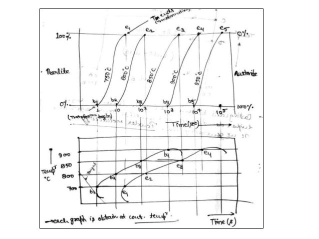
TTT diagrams for different carbon concentrations example ...
Phase diagrams are graphical representations of the phases present in an alloy at different conditions of temperature, pressure, or chemical composition. The diagram describes the suitable conditions for two or more phases to exist in equilibrium. For example, the water phase diagram describes a point (triple point) where water can coexist in three different phases at the same time. This happens at just above the freezing temperature (0.01°C) and 0.006 atm.

IRON CARBON EQUILIBRIUM DIAGRAM, TTT DIAGRAM AND HEAT ...
This video will provide you complete details about Time Temperature Transformation Curve & development of Non equilibrium Phases,Difference between Iron Carb...

A Man in a Bowler Hat (1976, printed 2005) // Dawoud Bey American, born 1953
Iron-Carbon(Fe-C) phase diagram. The iron-carbon phases and phase diagram is slightly complex, compared with other diagrams. The horizontal axis of the Fe-C ...

Ttt Diagram For Eutectoid Steel
Iron-Iron Carbide Phase Diagram - Callister. Austenite is a polymorph of iron, in a face centred cubic (FCC) structure. Carbon is relatively soluble in this phase (up to 2% C at 1100°C). It is therefore found in mild carbon steel above the eutectoid temperature of 727°C. As it cools, the austenite transforms into the much less carbon soluble ...

green pine trees on snow covered ground during daytime
Download scientific diagram | Calculated TTT diagrams for 0.2C (a) 0.3C (b) and 0.4C (c) steels. (Grain size 30 μ m, austenitization temperature 1 150°C). Applied holding temperatures also shown. from publication: Effects of Carbon Content and Cooling Path on the Microstructure and Properties ...
IRON CARBON EQUILIBRIUM DIAGRAM, TTT DIAGRAM AND HEAT ...
, with carbon concentrations up to a few percent you need to worry. Graphite might form, depending on conditions. For ... , the usual thing nowadays, you need to worry, too. Some alloying elements, in particular silicon (Si) but also nickel (Ni), promote graphite formation. ... TTT Diagrams: 1.

iron carbon phase diagram | Ceramic and Metal micrographs ...
Oct 11, 2017 · IRON CARBON EQUILIBRIUM DIAGRAM, TTT DIAGRAM AND HEAT TREATMENT 1. IRON CARBIDE DIAGRAM TTT DIAGRAM & HEAT TREATMENT By: Ankit Saxena 2. IRON-C phase diagram 3. From previous fig of FE-C diagram 4. • Hypo-eutectoid steels: Steels having less than 0.8% carbon are called hypo-eutectoid steels (hypo means "less than").

Sparky's Sword Science: Alloys, Microstructures and Phase ...
1) Equilibrium phase diagrams, Particle strengthening by precipitation and precipitation reactions 2) Kinetics of nucleation and growth 3) The iron-carbon system, phase transformations 4) Transformation rate effects and TTT diagrams, Microstructure and property changes in iron-carbon system Contents

1000+ images about Science & Engineering on Pinterest ...
white animal skull on white surface

Iron Carbon Ttt Diagram

Garniture for Field and Foot Tourney at the Barriers (c. 1575) // Italian, Milan
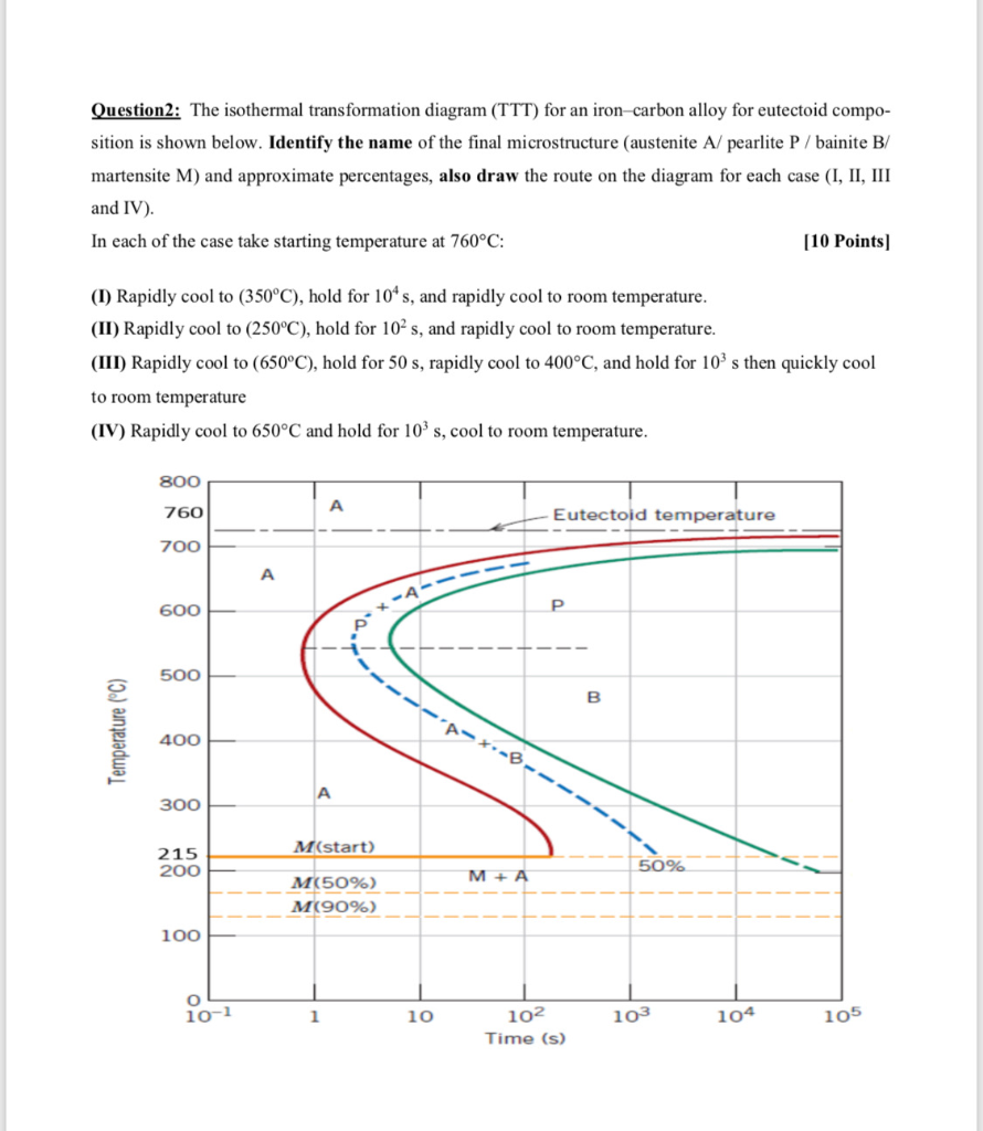
Solved: Question2: The Isothermal Transformation Diagram ...
IRON CARBON EQUILIBRIUM DIAGRAM, TTT DIAGRAM AND HEAT ...

Iron Carbon Ttt Diagram

gas station

black metal frame glass cross decor


Comments
Post a Comment