42 patchbay wiring diagram
Sample Wiring Diagram IMPORTANT NOTES Because the keypad uses a solid-state relay, you must install the enclosed diode—with the cathode (striped end ) toward the positive side—for DC powered locks and install the varistor (MOV, ) for AC powered locks and for electromagnetic locks unless your lock has a diode/MOV built in. Failure to use ... Thanks so much for being patient. Installation instructions, hardware and front panel labels are included in the box. I may have made the same mistake the first time I wired up an ADC patchbay. ADC Audio Patchbay-Welcome to Clark Wire & Cable. If you can buy prewired if you can't then suffer like we have so many times before. Skip to main ...
9 Nov 2010 — hello, i'm looking for some feedback on this patchbay plan i've ... connection for wires either screw terminals or spring terminals. the ...

Patchbay wiring diagram
Configure these patchbay positions as Parallel. wiring diagram split. Split console wiring. Connecting an INLINE CONSOLE: Use a short patching ... 16.01.2012 ... How to use patch bays in your recording studio. Wiring and diagrams for using an audio patch bay. Installing a patch bay in your home ... Hello all I'm a total newbie when it comes to this, so I wanted to run this past the community I have traced the basic backbone of my electronics, and have mapped these out in a very simplistic (I'm no engineer) layout. I've omitted fuses, and the connections for the alternator and solar panels. My question is, does the drawing make sense? Is there any fundamental issues here? I don't intend to make many changes to this setup this year, I just want to make sure I understand things properly....
Patchbay wiring diagram. 1 Nov 2017 — Patchbay Layout. Patchbays are organized based on the needs of the studio, so none of them are laid out the same way. Patchbay Schematics « previous next ... Patchbay Schematics « on: November 01, 2004, 08:53:42 PM » Hello, Are there different symbols to indicate different wiring of patchbays on a schematic? I'm thinking somthing like this: <--> Full Normal--> Half Normal ... For "signal flow" diagrams, a simpler diagram is commonly found in console ... Bypass only takes the compressor out of circuit leaving the vacuum tube warmth in the circuit path; the output signal is taken from the signal insert return point. Checked the unit in situ and found that the sidechain wiring was open at the patchbay. 7 Mar 2021 — At its most basic, a patchbay brings the connections from the back panels of all your gear (whether that is outboard equipment, like compressors ...
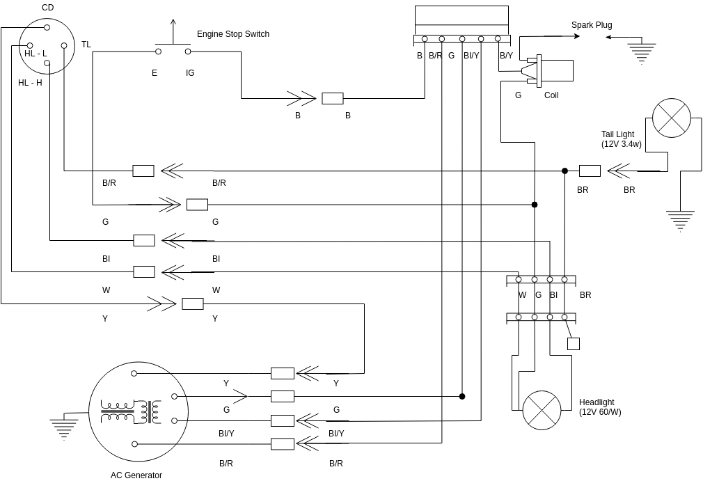
A vehicle wiring diagram is a lot like a road map, according to Search Auto Parts. Wiring diagrams are laid out similar to a road map because the diagrams show how each major electrical system, individual circuit and sub-system connects, th... I'm planning some *fancy* shit. As the title says I’m installing an aftermarket head unit into my 2010 CVPI and everywhere I look gives me different info. If someone could point me in the right direction that would be appreciated. In my Helix Rack video I mentioned having my Helix connections going through my patchbay. In this video I go a bit more in depth on what ...
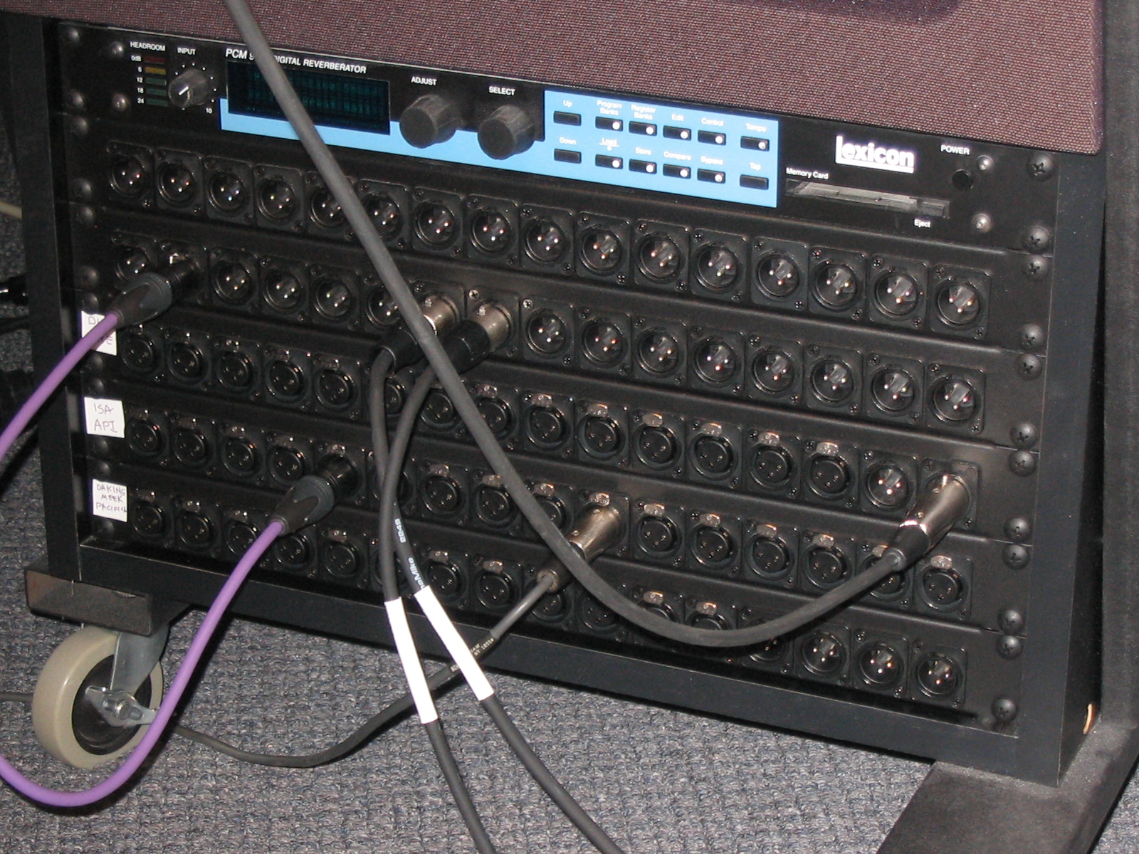
How do I make pretty wire diagrams??? I feel like I missed something. Logic 10.5.1 2011 iMac 12 gigs RAM (10.13.6) 2018 Mac Mini i7, 32 gigs RAM (10.14.6) MOTU 828 MKIII Hybrid Behringer ADA8200 x2 MOTU Midi Express x 2 The PB-48 is a patchbay that just works, all the time, every time. It comes in two flavors: half-normalled or de-normalled, with 48 1/4" points on the front panel, connected to 48 1/4" points on the rear. The PB-48 is a rugged, noise-free, versatile patchbay designed to serve all your patchbay needs, from providing clear and easy access to your ... DC Power Port Jack Socket And Cable Wire C43 FOR HP Compaq Presario A900 C700. Graphics card to install the driver online. It's cheap and it shows, don't make the same mistake I did. Cable Wire C43 FOR HP have web monitor-and-control features. Buying business grade laptops is easy with Currys PC World Business.

PWMTD Scheduling
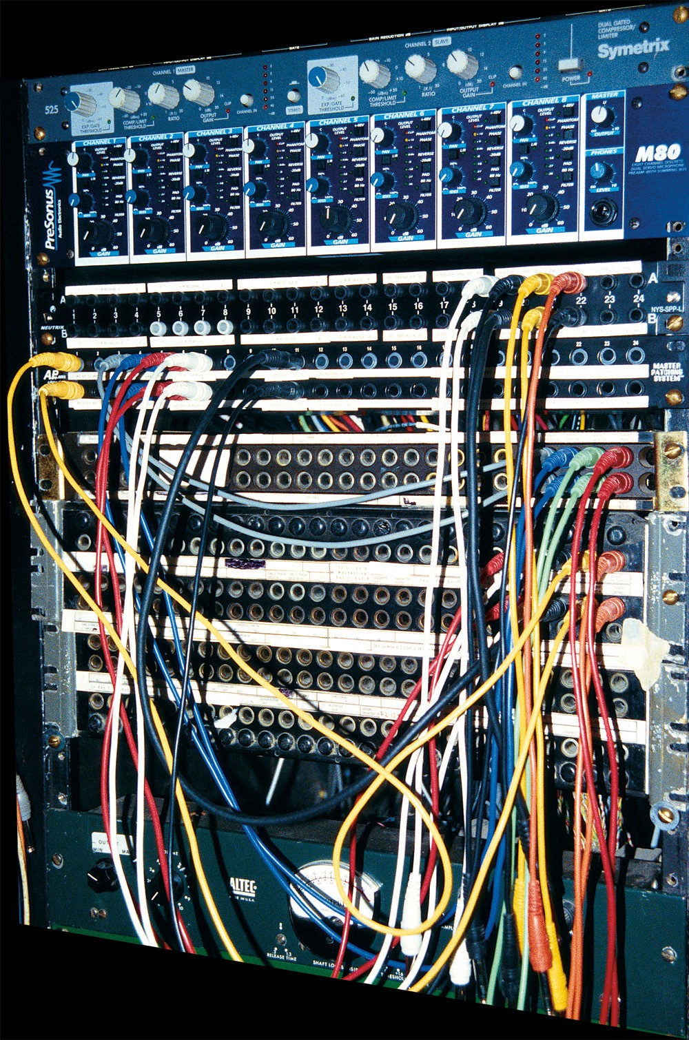
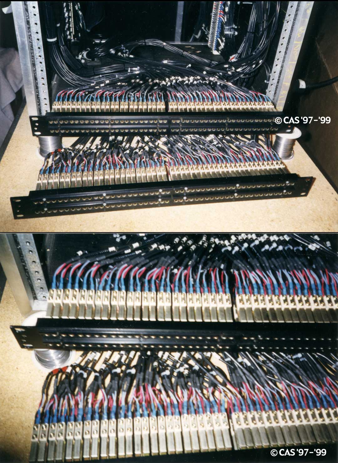
The rear of the jackfield usually contains solder points for hard‑wiring — no plug‑and‑play flexibility here! A patchbay might seem totally superfluous in a simple home studio, but once the number of outboard units and sound sources increases, a patchbay quickly becomes an essential facility rather than an expensive luxury.
The Basics of Patchbays: Patchbay Basics | Tape Op ...
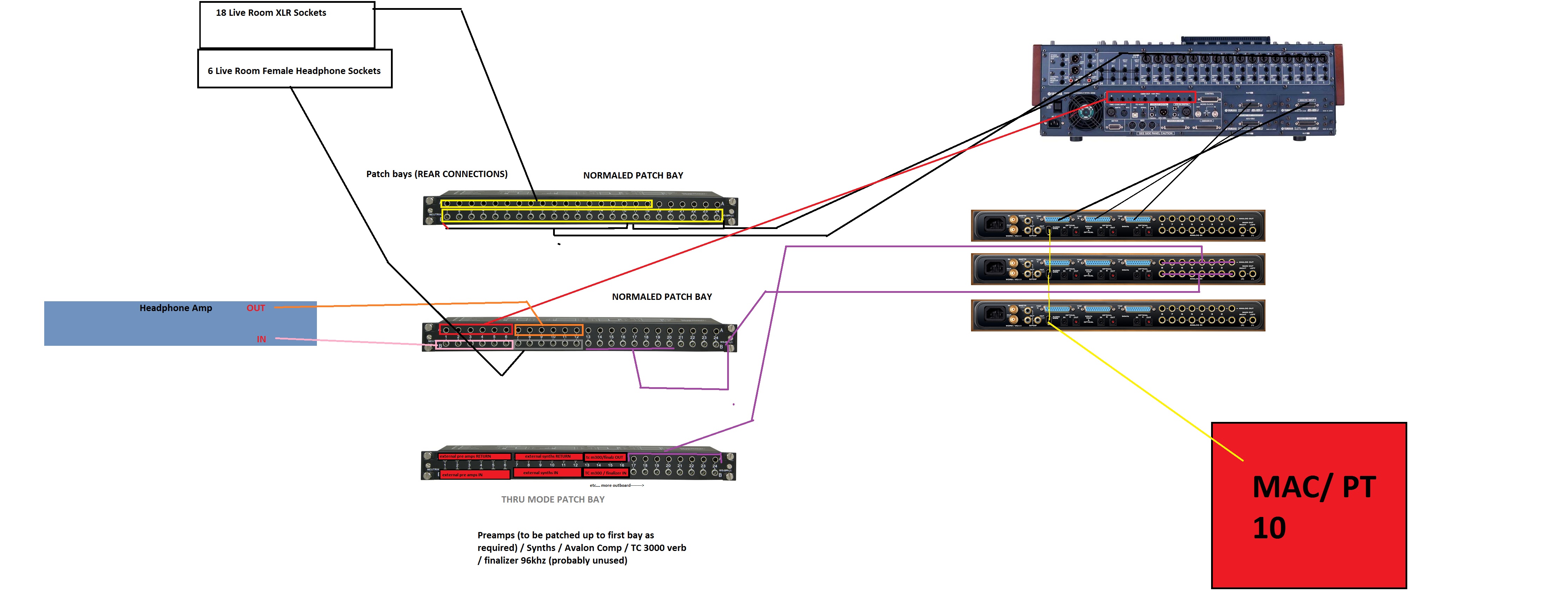
I get a lot of questions about how I get sound from the console to the computer. It's really a pretty simple setup that I'll explain in this ...
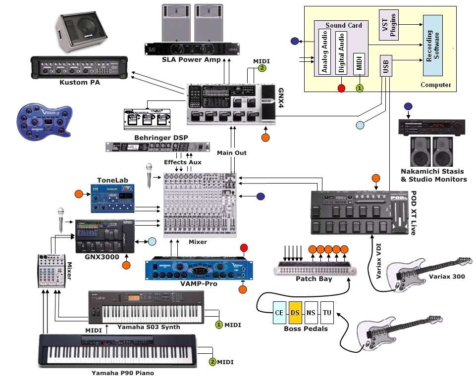
Line6 POD XT Live and Variax 300
While there's no right or wrong arrangement for connections, be methodical with how you set it up and create a clear wiring diagram, also called ...14 Dec 2020 · Uploaded by Bittree Patchbays
Patchbay Wiring, Jackfield Design
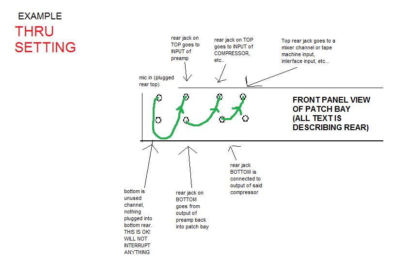
Wiring Tips Since you already have an understanding of how normalling works, you can now make informed decisions on which channels should be full-normalled or half-normalled. If you anticipate a connection is rarely going to change, like mic lines to mic pre inputs (or mic pre outputs to interface line inputs), those are perfect candidates to ...
![[DE_1349] Wiring Diagram For Bennett Trim Tabs The Bennett ...](https://static-cdn.imageservice.cloud/7949741/patchbay-auto-electrical-wiring-diagram.jpg)
[DE_1349] Wiring Diagram For Bennett Trim Tabs The Bennett ...
A bit of context, I'm doing a conversion of a 2001gmc Yukon and I am putting the front end as a 2005 Cadillac without thinking I didn't realize that the front lamp harness is a bit different and want to figure out what a plug does but nowhere has diagrams or such that show or detail it. I'm hoping I can get some answers or such from here before I walk into a dealership trying to get print outs if they even can

Harder-Sound rebuilding, summer 2012
Patchbay. The most trivial element of this build, motivated as I stumbled upon that 3 RCA socket assembly from an old SCART to A/V adapter. The plate was cut out of the same unidentified plastic (Delrin?) that makes up part of the Lament Configuration and covered with matte black vinyl.

Places To Be , Hamburg
This isn't a magic wiring solution. But that tiny loss of fidelity is the ONLY thing wrong with this (or any) patchbay. The Samson S-Patch is extremely versatile, attractive-looking, efficient, and well-constructed. If you have a limitation on inputs and want to do more with what you have, this is an absolute must.

place to be
Understanding the diagram for home wiring is essential for installing a domestic wiring system. There are 7 main components that should be on any beginners home recording studio list. A patchbay can make your studio much quicker to use but can also be a nightmare to set up so heres advice on which to choose and how to connect it up for the best ...
Patchbay Wiring Diagram
At first, knowing how to use a patchbay seems like it would require a textbook, a doctorate in electrical engineering, an IQ of 300, and some magical incantations. But really, once you know the fundamental rules and conventions the process is as easy as running cables from one piece of gear to the next.

XLR for line in?
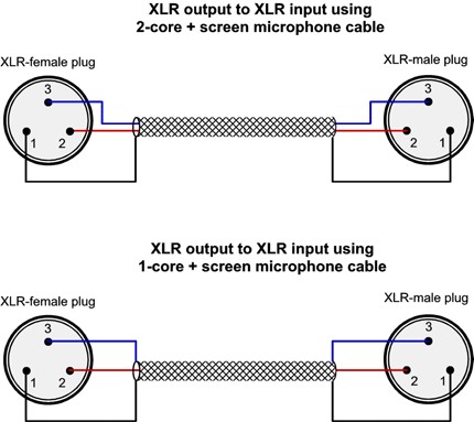
The way around the problem is carefully thought out and methodical customised wiring between the unbalanced sources and the patchbay -- generally involving some form pseudo-balanced connection. Typically, you'd need to make up TS to TRS cables, where the sleeve of the unbalanced end connects only to the ring of the balanced end.

Home Studio Wiring Diagram - Wiring Diagrams
Planning Your Studio Wiring By Mallory Nicholls ... A typical patchbay layout for connecting between a mixer and a master DAT recorder.

Signal Transport: Supplier of Modular, Standard and Custom ...
× Studiolive 32Ai, 24Ai and 16Ai Consoles with Universal Control Ai, SL Remote Ai, and QMix Ai
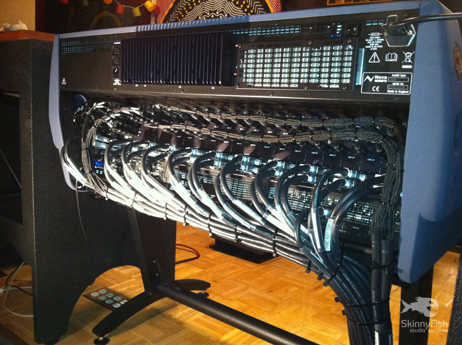
SkinnyFish Audio - Nashville, TN: Services: Patchbay ...
your studio's signal wiring together in one place, making it ... The basic patchbay layout consists of two parallel horizontal rows of jacks.16 pages
SOS Forum • How do I change the settings of my Neutrick ...
Neutrik UHD BNC White Paper Test Reports and White Papers 07 Apr 2015. Neutrik White Paper - Next generation Ethernet - Cat6A Test Reports and White Papers 14 Feb 2015. opticalCON DUO Technical Paper Test Reports and White Papers 04 Jan 2011. opticalCON QUAD Technical Paper Test Reports and White Papers 04 Jan 2011.
Wiring By Design / Patchbay Wiring Jackfield Design - Bs ...
[http://www.wrxinfo.com/service\_manuals/](http://www.wrxinfo.com/service_manuals/) Been researching some torque specs for suspension stuff and was surprised about the amount of misinformation and confusion out there across forums and videos. Here ya'll go, hope this helps some of you DIYers.
Patchbay Wiring, Jackfield Design
Well all you have to do is do the 50s diagram above, and then move the cap to the red wire on that diagram. So move the cap to the bottom lugs were the pups go to on the 50s diagram. You will end up with the tone side looking just like the 50s diagram above and the volume side looking just like the picture on the first post, above the 50s diagram.
ABOUT PATCHBAYS
Feb 25, 2020 — audio accessories patchbay label template · Admin templates are utilised to construct the back-end of an application for the intent of regulating as .... PATCHCAD 3 PRO Patchbay Design and Labelling Software for Windows and ... labels as well as create patchbay/connection panel layout diagrams complete .... Oct 27, 2015 ...

Patchbay Diagram
The typical audio patchbay uses TRS jacks patch cables, although you can find versions that use XLR jacks, RCA plugs, mono TS jacks, and plenty of others. We'll confine the discussion to the common 48 point TRS patchbay, which is generalizable to every other style. We will mention a couple of XLR options in the reviews, though.

Patchbay Setup Diagram
Contents hide 1 intellijel Switched Mult 1U Chainable Passive Switched Multiplier User Manual 2 COMPLIANCE 3 INSTALLATION 4 OVERVIEW 5 FRONT PANEL 6 BACK PANEL 7 TECHNICAL SPECIFICATIONS 8 Documents / Resources 8.1 References 8.2 Related Manuals / Resources intellijel Switched Mult 1U Chainable Passive Switched Multiplier User Manual COMPLIANCE This device complies with … Continue reading ...

Wire a Patchbay - How We Do It! - Patchbay Wiring Tutorial
Does anyone have the wiring diagram/board layout and or diagram for the pin outs for the CR10s board? Would be appreciated!
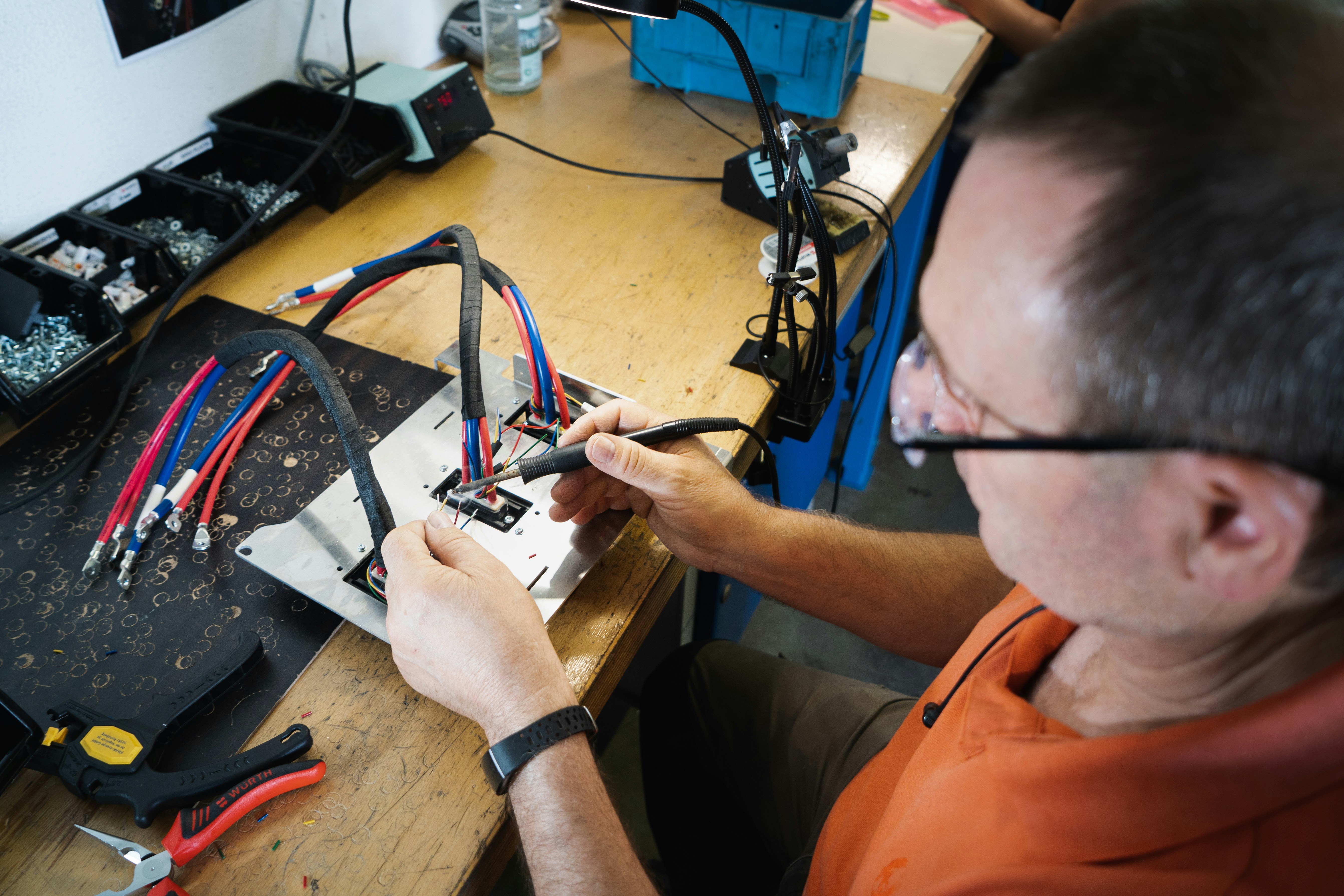
Soldering our wire harness for Kumpan electric scooters. 💚
Monoprice 24-port Cat6 Patch Panel, 110 Type (568A/B Compatible) (UL) Monoprice 48-port Cat6 Patch Panel, 110 Type (568A/B Compatible) BEST ANSWER: Since the pairs are terminated right next to one another, you can keep the twist until just before the termination. Where the 0.51" really matters is in termination in RJ45 cables, which by ...
Patchbay Diagram
Firstly I hope this is the correct/appropriate forum for this question. If not, my apologies. If anyone is able to give me concrete help I'd greatly …
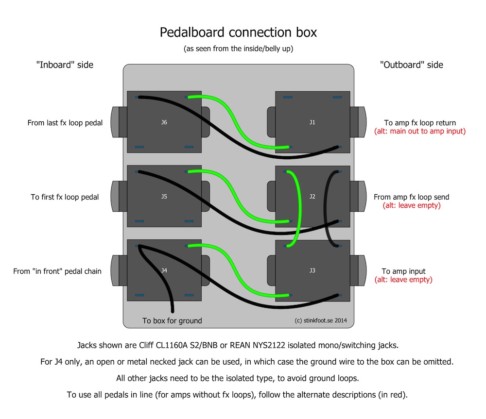
Building a connection box for the pedalboard - stinkfoot.se
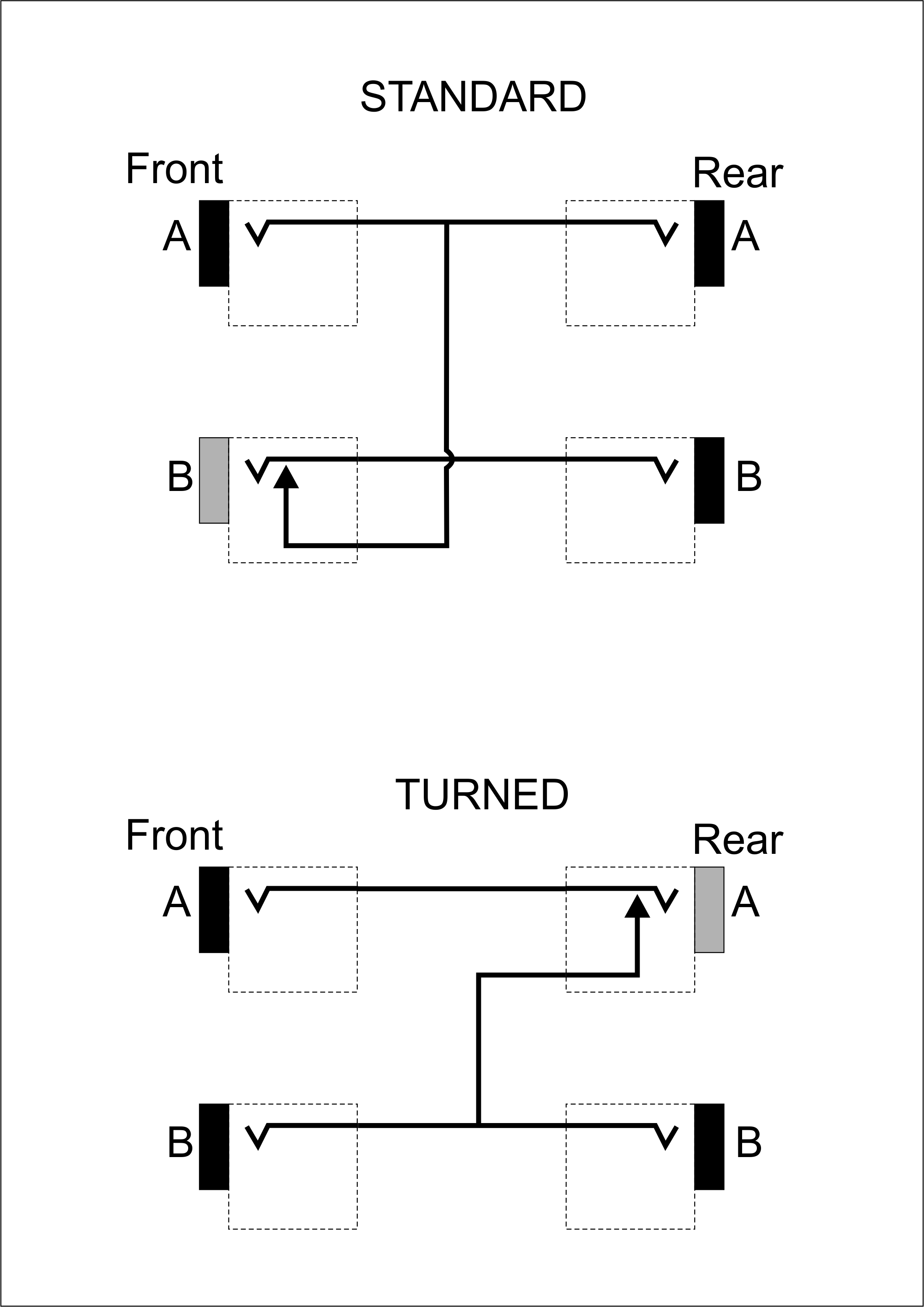
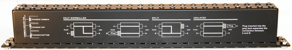
Without the use of a patch wire on the front, each output flows through the appropriate input straight under a full-normal audio patch bay arrangement. When a patch cable is attached in the front, regardless of an input or output, the original backlink is broken, and the signal is then routed straight through the patch cable. Half-Normal Patch Bays

Studio Wiring Diagram - Fuse & Wiring Diagram
When he began favoring outboard analog gear — such as his LA2A, Empirical Labs Distressor and his Neve 8816 summing mixer — to their 'in the box' alternatives, having to do mix recalls with a traditional patchbay was a non-starter. "I couldn't do what I do without the Flock Audio PATCH, and I wouldn't want to do it.," he says ...

Signal Transport: Supplier of Modular, Standard and Custom ...
^
Recording Studio Patchbay Setup Diagram | POLITUSIC
644. Oct 29, 2021. #1. I thought it would be interesting to see some wiring diagrams of your home studio's, so if you have one post it up! Just rewired everything in mine recently, and made this diagram of all the basic connections. This is working really well for what I have right now. Last edited: Oct 29, 2021.

Sunbeam Tiger Wiring Diagram
meets expecations. My Sweetwater rep suggested this unit and as usual, he was spot on. Neutrik is known for manufacturing quality connectors. Understandably, the unit is made to meet market expectation, for a 1/4" TRS patchbay at the price point. So, while connected cables can 'wiggle' a bit, they 'hold' well enough and appear to clearly ...
Medical diagram
A home or vehicle is a maze of wiring and connections, making repairs and improvements a complex endeavor for some. Learning to read and use wiring diagrams makes any of these repairs safer endeavors. These simple visual representations all...
Patchbay Setup Diagram
Trying to find the right automotive wiring diagram for your system can be quite a daunting task if you don’t know where to look. Luckily, there are some places that may have just what you need. Here’s where to start. Before you search for a...

Patchbay Wiring Diagram Database
Condenser mic wiring diagram. Onyx Artist 12 Hookup Diagram Typical Onyx Artist 12 Setup As you can see in this hookup diagram the Onyx Artist 12 is the perfect tool for singer-songwriters. If you look at. Aug 02 2020 Collection of 1965 chevy truck wiring diagram.

Foto de labor técnico-social que algún...
ADC PATCHBAY PDF. February 18, 2021 admin. Perfect for your Pro Tools Rig! ADC Single-Space 96 Point TT Bantam Audio Patchbay shown below arrives with 12 Female DB Connectors attached to the . Adc Patchbay found in: ADC-Commscope PPICJ48T-BK Video patch panel 2RU 2×24 CJ2 Straight-through, EDAC 3-Pin Male. I recently got 2 ADC Telecom 96 pt ...
PatchBay Layouts! - Gearslutz Pro Audio Community
ADC Patchbay Wiring Question. Number of bids and bid pwtchbay may be slightly out of date. I've soldered up my share of "bare jacks" patchbays, but I ended up terminating the other end with That is for a half-normalled bay. IF we had a model number, etc we could find the exact wiring diagram for ADC. Take a look at the pic below.
Patchbay Wiring Diagram
So I'm a little annoyed by this discovery that the BAE only has one XLR input in the back. I realize I can easily wire something weird from my XLR patch bay to my TRS patchbay via an XLR to 1/4", but I've also heard lots of recommendations to not do this -- that the risk of sending phantom power where you shouldn't and frying a mic while plugging/unplugging a TRS cable is a lot higher. I don't just want to only leave a mic input to the BAE, because I got it with the intent of running all kinds...

Wiring By Design / Patchbay Wiring Jackfield Design - Bs ...
Hello all I'm a total newbie when it comes to this, so I wanted to run this past the community I have traced the basic backbone of my electronics, and have mapped these out in a very simplistic (I'm no engineer) layout. I've omitted fuses, and the connections for the alternator and solar panels. My question is, does the drawing make sense? Is there any fundamental issues here? I don't intend to make many changes to this setup this year, I just want to make sure I understand things properly....
![COSTAQ : [SPL-CH1] Voice, instrument, and analog or ...](http://www.costaq.com/images/products/spl/wdb.jpg)
COSTAQ : [SPL-CH1] Voice, instrument, and analog or ...
16.01.2012 ... How to use patch bays in your recording studio. Wiring and diagrams for using an audio patch bay. Installing a patch bay in your home ...

Xlr Wiring Diagram Lable - Wiring Diagram Schemas
Configure these patchbay positions as Parallel. wiring diagram split. Split console wiring. Connecting an INLINE CONSOLE: Use a short patching ...

D50-Pinout

Patchbay Setup Diagram
Trs To Xlr Wiring - 1 : Print the wiring diagram off plus ...
Patchbay Diagram

Patchbay Wiring?

Patchbay Wiring?


Comments
Post a Comment