43 40 amp relay wiring diagram
Spdt Relay Wiring Diagram – Wiring Diagrams Click – 12 Volt Relay Wiring Diagram. Wiring Diagram comes with a number of easy to follow Wiring Diagram Guidelines. It really is meant to assist all the common person in creating a correct system. These directions will be easy to understand and implement. 12v 40 Amp Relay Wiring Diagram. Hannah Ramirez September 6, 2021. 21 Gallery Of 12v 40 Amp Relay Wiring Diagram. 5 Pin Dc Relay Wiring Diagram. 5 Pin Relay Wiring Diagram 87a. 5 Pin Relay Wiring Diagram Fan. 5 Pin Relay Wiring Diagram. 12v 5 Pin Relay Wiring Diagram. 24v 5 Pin Relay Wiring Diagram.
Here are a number of highest rated 40 Amp Relay Wiring Diagram pictures upon internet. We identified it from obedient source. Its submitted by meting out in the best field. We agree to this kind of 40 Amp Relay Wiring Diagram graphic could possibly be the most trending subject gone we allowance it in google improvement or facebook.
40 amp relay wiring diagram
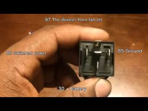
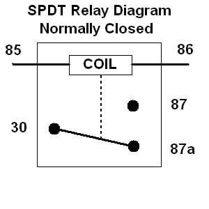
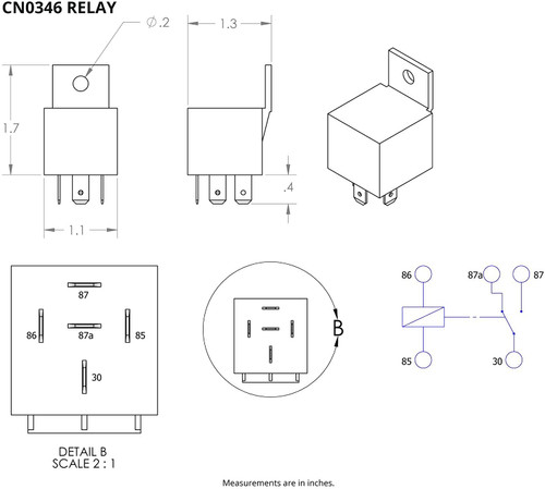
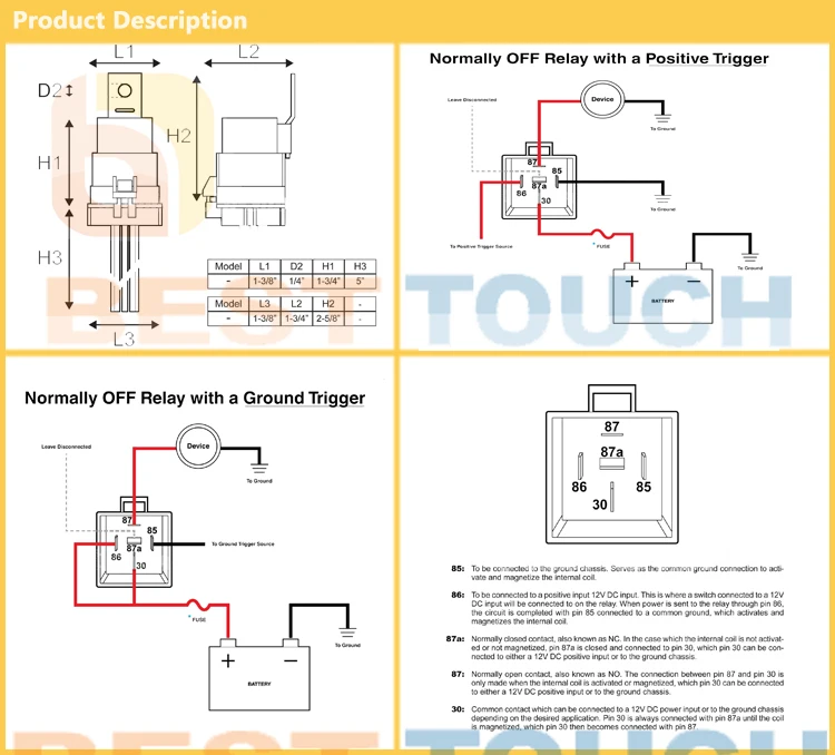
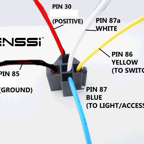
How they The following simplified circuit diagram is often used to easily understand how a relay operates: The numbers 85, 86, 30, 87 & 87a (or other numbers for different relay. The orange wire on the relay should see a 12 volt signal when the ignition switch is Each relay will control a single fan, and a 30 amp fuse is recommended for each As ... Feb 22, 2009 · Well, here are a few more wiring diagrams for Jeep Wrangler – this time for the Jeep YJ series years 1987 to 1994. The PDF includes ‘body’ electrical diagrams and Jeep YJ electrical diagrams for specific areas like: air conditioning units, typical jeep charging unit wiring diagrams, typical emission maintenance reminder wiring diagrams, front end lighting wiring … Dec 10, 2017 · The Main Electrical Panel Subpanels. Electrical service panels is the 200 amp worth extra expense wiring a breaker box bo square d homeline 40 e 80 connecting rv s power panel to main wire 320 class meter 2 sub with 200a es grounding rod conductor dimensions for 30 combo load center feed i have outside my house diagrams specifications kdm electric …
40 amp relay wiring diagram. 12V waterproof 5-prong relay (max 15.6V). 40 AMP / 30 AMP High switching capability Excellent waterproof and dustproof ability, high quality in any weather conditions 12v relays can operate with anywhere between 9v and 15.6v, so if you are looking for … 40 Amp 4 Pin Relay Wiring Diagram On 40 Images. Free Download with regard to 12V 30 Amp Relay Wiring Diagram by admin From the thousand pictures on the web about 12v 30 amp relay wiring diagram, we selects the top choices together with ideal resolution only for you all, and now this pictures is usually considered one of photographs series in our greatest photographs gallery with regards to 12V ... Jan 02, 2015 · High Wattage Headlights Wiring Diagram: This diagram is fo using high-wattage bulbs with stock headlights. Upgrading to 80-100 watt bulbs definitely requires the use of relays. The relay system bypasses the stock headlight wiring, which isn't heavy duty enough to handle the increased wattage of the new bulbs. Overload Relay Wiring Diagram. Whenever the flow of current toward the motor is more than what the heaters are charged for, the overload explores later than some seconds. The classes of overload relay can be classified into three types based on the duration of relay explore.
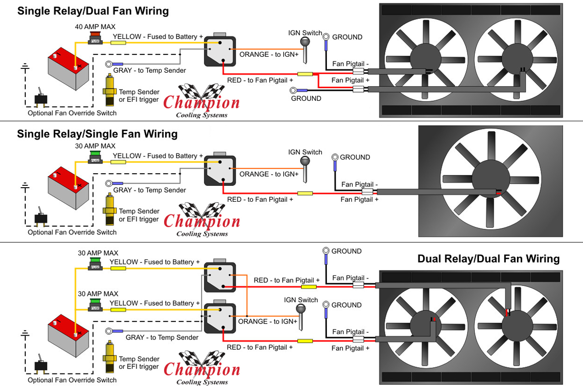
40/60 Amp Relay 3/8” NPT Brass Probe Diagram #2 Control Module (Wiring Continues on reverse side) Using the Blue #10 Butt Connector provided, attach the Red wire to the Negative (-) lead on the electric fan. If you are running two small electric fans, the total continuous amperage cannot exceed 25 amps. The Red wire can be connected in 12 volt 40 amp relay wiring diagram. The iso mini relay we have looked at above has 4 pins or terminals on the body and is referred to as a make break relay because there is one high current circuit and a contact that is either open or closed depending upon whether the relay is at rest or energised. Disconnect terminal of the battery 2. 01 11 ... This 4 pin relay comes with no labeling or wiring diagram. 40 amp 4 pin relay wiring diagram on 40 images. I never write reviews but i figured this would be a good one since i researched hi and low to figure out how to wire. These layouts are shown on the two 5 pin relays below pin 87a not present on 4 pin relays. Nov 30, 2019 · This is a image galleries about club car precedent fuse locationyou can also find other images like wiring diagram parts diagram replacement parts electrical diagram repair manuals engine diagram engine scheme wiring harness fuse box vacuum diagram timing belt timing chain brakes diagram transmission diagram and engine problems.
Blue Wire (+) Black Wire (-) To chassis ground (-) Diagram #1 KIT CONTENTS QTY. DESCRIPTION 2 Relay Wire Harness 2 40/60 Amp Relay TOOLS NEEDED Wire Stripper Crimping Tool IMPORTANT Each Relay will control up to two different fans with a COMBINED MAXIMUM DRAW OF 25 CONTINUOUS AMPS. Relay #2 Electric Fan #1 Electric Fan #2 87 87A 30 86 85 Orange ... Jan 14, 2022 · Home › 30 Amp 125/250 Volt Plug Wiring Diagram - Utilitech 50-Amp-Volt Black 4-Wire Grounding Plug at Lowes.com - To fully enjoy this autonomy it is necessary to have on board a comprehensive, fully operational and w. The overheating . Make supply connections to driver supply wires and ground wire lead using supplied wire connectors/nuts. The relay is a 30/40 amp yet they use 16 gauge wire. I have a 30 amp pump that I run, it got the wires so hot it melted the plug. Now I just crimp on the fast tabs and plug directly to the relay. They need to use 12 gauge wire. Other than that they work fine. Nov 05, 2021 · The diagram above outlines in the most simplistic terms, my camper van electrical design. Using the formula explained here, I calculated I’d need about 80 amp hours (ah) per day including contingency. Assuming the batteries are …
How to wire a 30/40 Amp relay
12 Volt 40 Amp Relay Wiring Diagram Fog Light. Print the wiring diagram off plus use highlighters to trace the signal. When you make use of your finger or perhaps the actual circuit with your eyes, it is easy to mistrace the circuit. 1 trick that We 2 to printing a similar wiring plan off twice.
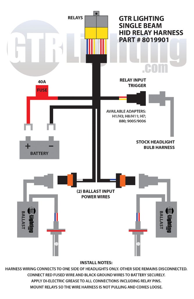
HID Relay Harnesses Explained - Better Automotive Lighting
Aug 28, 2016 · load. And if a relay fails, you will still have one fan running. RECOMMENDED WIRE SIZES: 8-10 GA: FAN POWER AND GROUND. 16-18 GA: ALL OTHERS. PAGE 4 OPTIONAL RELAY OVERRIDES TEMP SENSOR AND TURNS ON FANS WHEN A/C IS TURNED ON BATTERY 86 30 87 85 86 30 87 85 Optional override switch turns on fan, by …

Amazon.com: MICTUNING LED Light Bar Work Light Wiring Harness ...
Dec 10, 2017 · The Main Electrical Panel Subpanels. Electrical service panels is the 200 amp worth extra expense wiring a breaker box bo square d homeline 40 e 80 connecting rv s power panel to main wire 320 class meter 2 sub with 200a es grounding rod conductor dimensions for 30 combo load center feed i have outside my house diagrams specifications kdm electric …

How to wire open frame relay
Feb 22, 2009 · Well, here are a few more wiring diagrams for Jeep Wrangler – this time for the Jeep YJ series years 1987 to 1994. The PDF includes ‘body’ electrical diagrams and Jeep YJ electrical diagrams for specific areas like: air conditioning units, typical jeep charging unit wiring diagrams, typical emission maintenance reminder wiring diagrams, front end lighting wiring …
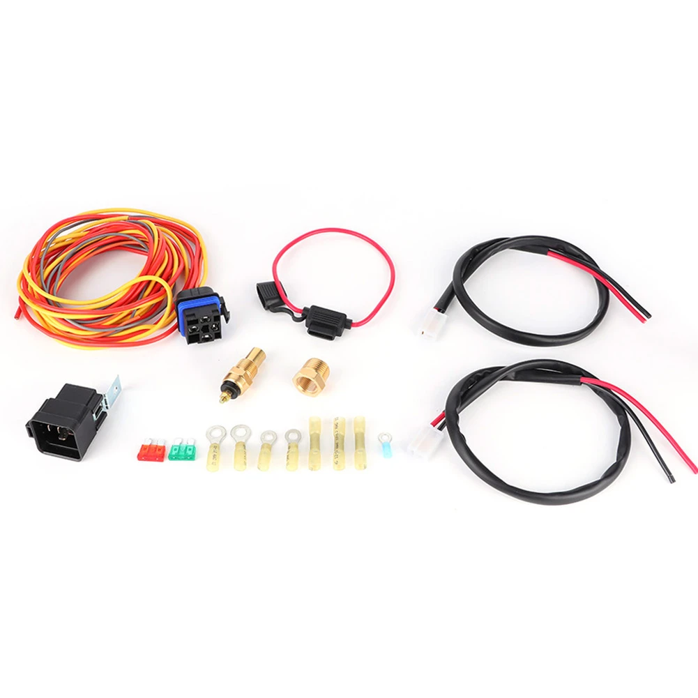
Electric Cooling Fan Wiring Harness Kit Dual Single 165/185 W ...
How they The following simplified circuit diagram is often used to easily understand how a relay operates: The numbers 85, 86, 30, 87 & 87a (or other numbers for different relay. The orange wire on the relay should see a 12 volt signal when the ignition switch is Each relay will control a single fan, and a 30 amp fuse is recommended for each As ...

How to Wire Dual Electric Cooling Fans

OLS Automotive Relay Switch Harness 12 AWG Hot Wires ...
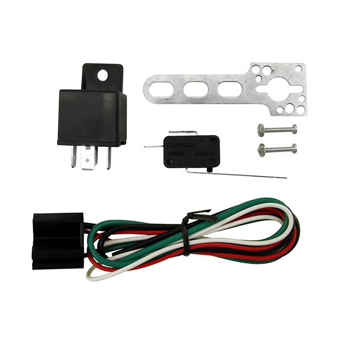
Wide Open Throttle Switch W/ 40 Amp 4 Pin Relay And Harness
Understanding Relays & Wiring Diagrams | Swe-Check

China 4 Pin 40 Amp Relay Manufacturers and Suppliers ...
![10 Pack Bosch Style 5-Pin 12V Relay Switch [SPDT] [30/40 Amp] 12 Volt Automotive Relays for Auto Fan Cars](https://www.ubuy.co.id/productimg/?image=aHR0cHM6Ly9tLm1lZGlhLWFtYXpvbi5jb20vaW1hZ2VzL0kvNzFHZkUrcVpYd0wuX0FDX1NMMTUwMF8uanBn.jpg)
10 Pack Bosch Style 5-Pin 12V Relay Switch [SPDT] [30/40 Amp] 12 Volt Automotive Relays for Auto Fan Cars

How to wire open frame relay

ONLINE LED STORE 6 Pack Bosch Style 5-Pin 12V Relay Kit ...

ZOMBIE Rocker Switch Kit by Arsenal Offroad TM 40 Amp Relay 30Amp Fuse Laser Blue LED SPST ON/ OFF Rocker Switch Wiring Harness Kits great for UTV SUV ...
PLEASE Help- Wiring 2 relays in parallel | All About Circuits

Buy 5 Pack - EPAuto 30/40 AMP Relay Harness Spdt 12V, 5-PIN ...

8 Pin Relay Base Wiring Diagram - DPDT Relay Diagram

How to wire open frame relay

Amazon Com Genssi 30 40 Amp Auto Led Light Bar Relay Wiring ...
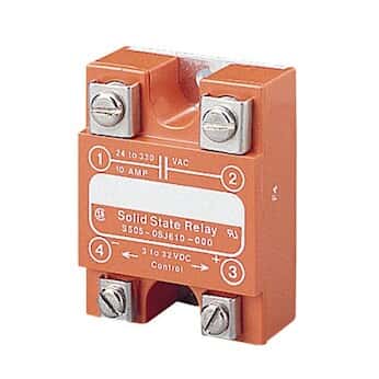
Solid State Relay, 40 Amps, with 90 to 280 V Control Input ...

Amazon.com: 5 Pack - EPAuto 30/40 AMP Relay Harness Spdt ...

madcomics: How To Install Relay For Fog Lights
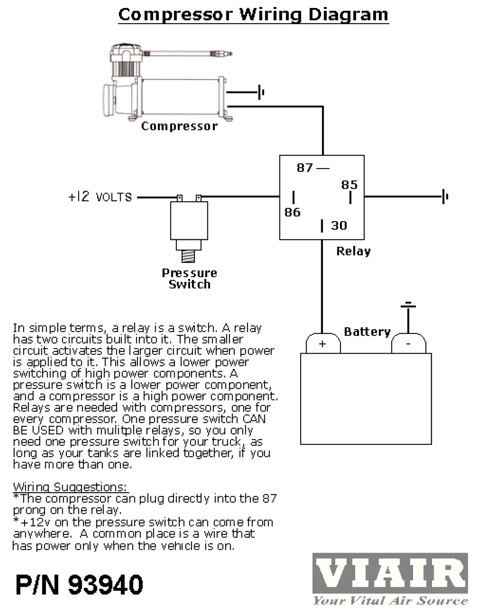
VIAIR 93940 40 Amp Relay Use and Care Manual | Manualzz

2 Pack 12V 30/40 Amp 5-Pin SPDT Automotive Relay Harness ...

40/30 Amp Waterproof Relay Switch Harness Set - 12V DC 5-Pin ...
Electrical - Relays & Switches - Page 1 - TEMCo Industrial
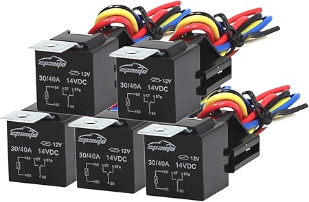
5 Pack - EPAuto 30/40 AMP Relay Harness Spdt 12V, 5-PIN SPDT Bosch Style
Relay 12 Volt 40 amp
Connecting Additional Devices to the Remote Turn On Wire ...

40 Amp CCPWM Instructions
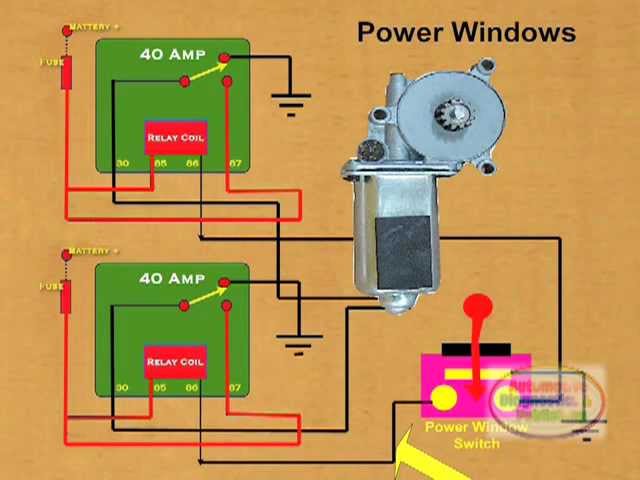
How to Wire a Power Window Relay - YouTube
5 Pin Automotive 5 Pack 30/40 Amp 12v Waterproof Spdt Relay ...
Understanding Relays & Wiring Diagrams | Swe-Check

How to wire open frame relay

Free Pdf Download » Search Results » Latching Relay Pdf

Electric Cooling Fan Wiring Harness Thermostat 40 amp Relay Kit 185/165 Degree

Using a Solid State Relay - Learn how to wire a solid state relay
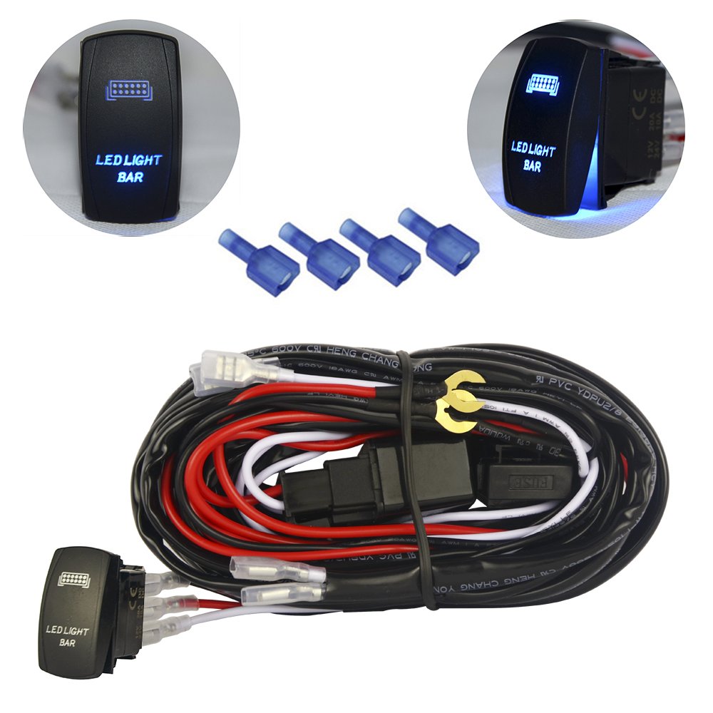
mictuning LED Light Bar Wiring Harness 40 Amp Relay ON-OFF ...

185/165 Thermostat 40 Amp Dual Electric Cooling Fan Wiring ...
Where Are My Instructions For My Fan Relay?
30/40 AMP Auto LED Light Bar Relay Wiring Harness SPDT 12V 40A (Pack of 5)
Thoughts on accessory fuse panel diagram | Tacoma World

Amazon.com: 4-PIN 40/30 AMP 12 V DC Waterproof Relay with ...


Comments
Post a Comment