43 micro switch wiring diagram
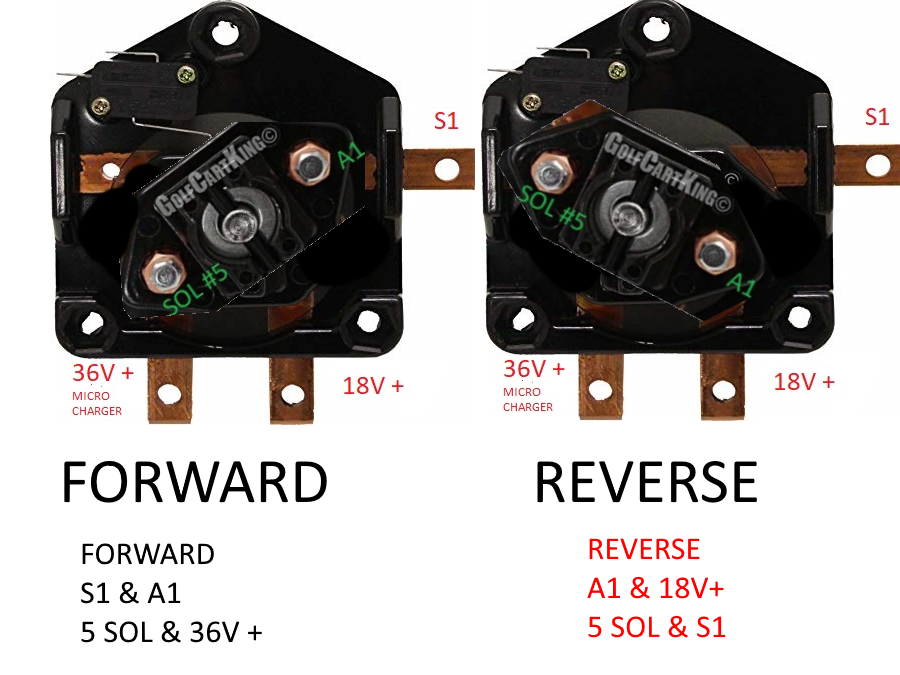
Wiring Diagram Next Generation Guardmaster Safety Relay (GSR) Bulletin 440R Quick Reference Page ... MSR41 Micro 400 GuardShield, E-stop 100S-C 3 4 e 0 74 DIS, MSR42 Micro 400 GuardShield, SensaGuard, E-stop 100S-C 3 4 e 0 ... switch on the first-opened guard and the switch on the last-closed guard. Faults are only detected at these times because EZGO Micro Switch Wiring Diagram. As per the EZGO micro switch wiring diagram, there are four wires coming out of the main micro switch. The wires are divided using two individual spades. On one side, there is a white wire which connects to the ignition shutoff module and a black wire that connects to the key switch and also goes to the ground.
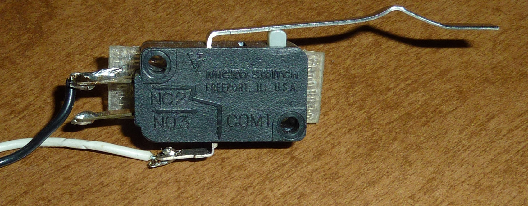
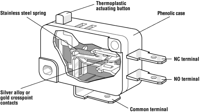
2,549. Feb 22, 2013. #3. The three terminals on a micro-switch should be marked as C, NC and NO. If they are not marked, it is easy to figure out using a meter. If you don't know how to do that, I wouldn't want to fly in the airplane you are working on. I know it sounds harsh, but it sure sounds like a major safety issue to modify cowl flaps on ...

Micro switch wiring diagram
Sep 21, 2016 · Fan motor dimmer switch diagram Message. (Note that this an Basic guide of single phase AC (alternating current) fan speed regulating) I hope now you understood the ceiling fan speed control wiring diagram or ceiling fan motor speed controlling switch diagram. Now if you have any question regarding this post then you can use comments section. Nov 04, 2018 · 1 way light switch wiring diagram; 1/4 speaker cable wiring diagram; 10 switch box wiring diagram; 100 amp manual transfer switch wiring diagram; 100 amp service panel wiring diagram; 1000 watts power amplifier schematic diagram; 11 pin relay wiring diagram; 110v plug wiring diagram uk; 12 pin trailer socket wiring diagram; 12v 2 prong toggle ... Club Car DS 1984-1985 Gas Model Wiring Diagram Typical Diagram For Club Car DS Gas 1984-85 Older Version There was a small change in …
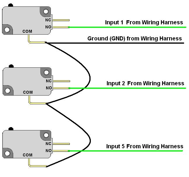
Micro switch wiring diagram. See DIAGRAM Connect a Blue wire from the key switch to terminal 2 on the Golf/Street switch, and the Brown wire to terminal 1. Installation Instructions for the ISSUE 4 MICRO SWITCH™ Heavy Duty Limit Switch Series PK wiring and conduit connection is made to the base receptacle. This feature also reduces MICRO SWITCH™ HDLS Mounting Diagram. 4 pin micro switch wiring diagram. Two 2 prox switches option Figure 2. 4 Pin Relay 4 pin relays use 2 pins 85 86 to control the coil and 2 pins 30 87 which switch power on a single circuit. Finally the modulation wire will go on the remaining pin. Below is the schematic diagram of the wiring for connecting a DPDT toggle switch. The most common components are capacitor, resistor, and battery. Additionally, there are other elements like ground, switch, motor, and inductor. All of it rides on circuit that is being constructed. According to previous, the traces at a Ezgo Wiring Diagram represents wires. Sometimes, the wires will cross. familiarize themselves with installation and wiring instructions in addition to requirements of all applicable codes, laws, ... Enabling Switch (GripSwitch) with ... 8-pin micro (M12) 1. 2.1 889D-F8AC-5. DC Micro (M12) Cordset ...
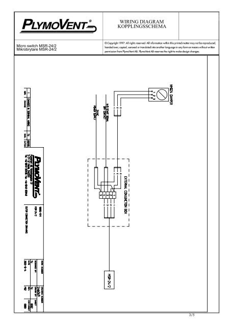
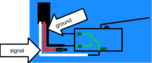
Jul 11, 2019 · 100 amp manual transfer switch wiring diagram; 100 amp service panel wiring diagram; 1000 watts power amplifier schematic diagram; 11 pin relay wiring diagram; 110v plug wiring diagram uk; 12 pin trailer socket wiring diagram; 12v 2 prong toggle switch wiring diagram; 12v 3 way toggle switch wiring diagram; 12v led strip light wiring diagram Ansul System Wiring Diagram – ansul fire suppression system wiring diagram, ansul system micro switch wiring diagram, ansul system wiring diagram, Every electrical structure consists of various different components. Each part should be set and linked to other parts in specific manner. If not, the structure will not work as it should be. These are: • Micro switch. • Battery. • An electrical device such as bulb. • Wire (5amp red and black) • Soldering iron. • Plier to cut wires. • Clamps to hold wires while they are being soldered. It is necessary you have these items at your disposal in order to make the entire process very smooth and hitch-free. The snap action switches have three output contact strips denoting common (C), open (NO) and closed (NC). When the switch is actuated, depending on how you wire, the contacts will open or close while the plunger is being pressed. Here’s a quick wiring diagram for your reference. JMP Snap Action Switches are a simple solution where ...
Positive switch wiring diagram for Nissan Models: R51 Pathfinder 2005-2012, DU40 Navara 2008-2014, GU4-7 Patrol 2000-2012, Y61 Patrol 2013-On, Y62 Patrol 2013-On, T31 X-Trail 2007-2013 Negative switch wiring diagram for Nissane models: Apr 05, 2021 · The most common design uses a micro switch (also known as lever switch), but the same design works with reed switches, other SPDT switches and is also very similar when using an opto-interrupter (ex TCST2103). The lever switch is a single pole double throw switch. The switch has a single output pin called the common and labeled as C. Ansul micro switch. B8f Xantrex Charge Controller Wiring Diagram Wiring Resources. Run a low voltage wire from the 12v micro switch in the ansul system to the 12v shunt trips. If an ANSUL fire system is present the fire system micro – switch will need to be wired to terminals as indicated on the installation diagram. Wiring Diagram Trailer Plugs and Sockets. Narva 7 and 12 pin trailer connectors comply with all relevant ADRs. Flat connectors comply with Australian Standards AS4177.5-2004. Large and small round connectors comply with AS2513-1982 while Heavy duty connectors meet the AS4735-2003 standard as required for vehicles and trailers over 3.5 tonnes.
Glen's Home Automation: Installing the Insteon Micro On ...
This video is aimed at anybody who is not very experienced with electronics and wants to know how to wire up a micro switch into their electrical system.
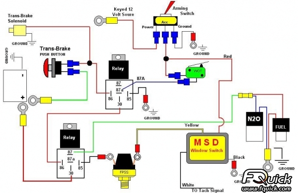
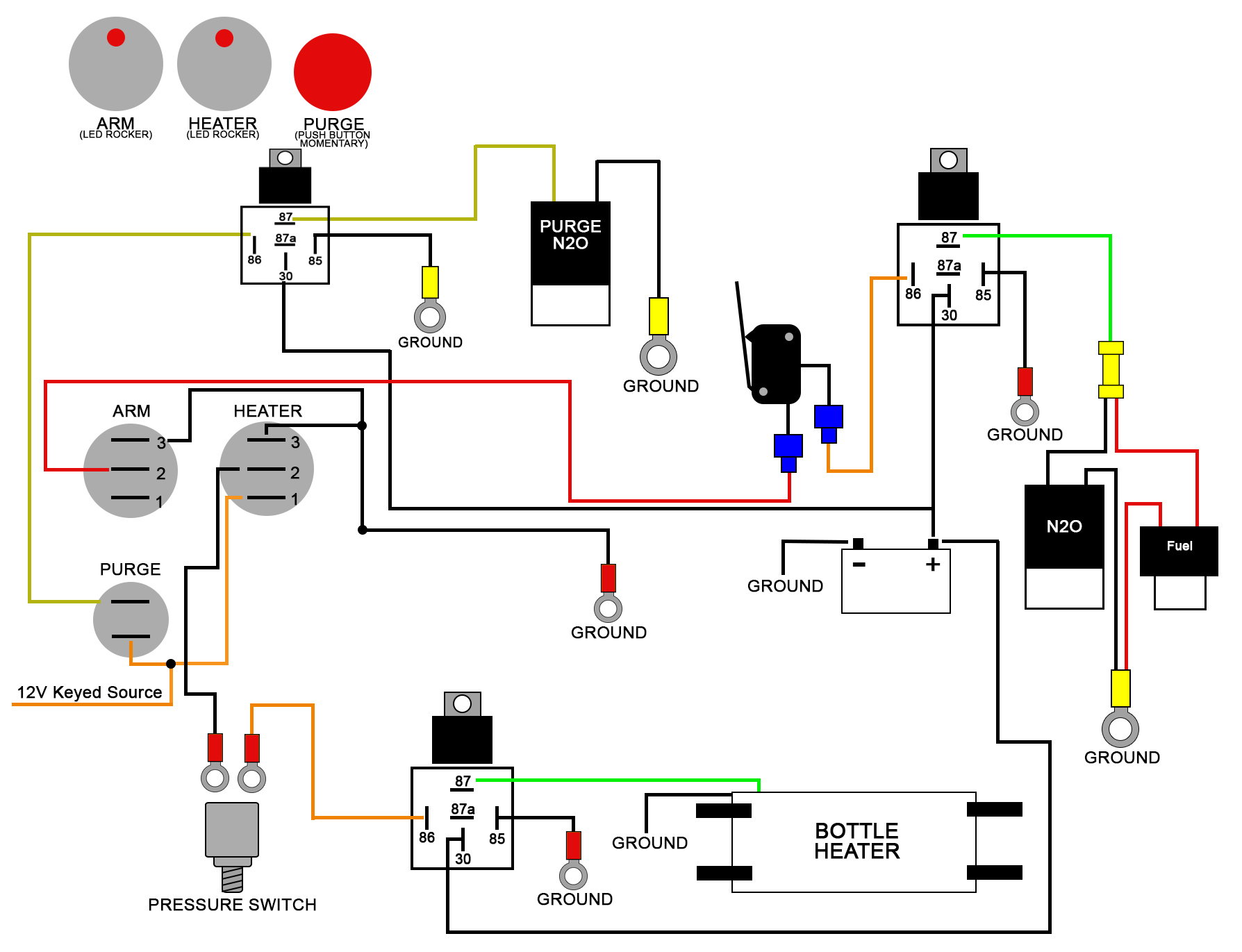
Nitrous Related Wiring - Page 13 - LS1TECH - Camaro and ...
What is a micro switch diagram? This is a diagram which displays the various components of a micro switch in order to help you know how it is wired. If you are using a micro switch for the first time, it is important to know how the components have been structured. This gives you a clue on how it can be wired to ensure proper functioning.

Micro Switch Wiring Diagram Fe290 Pedal Start
Club Car DS 1984-1985 Gas Model Wiring Diagram Typical Diagram For Club Car DS Gas 1984-85 Older Version There was a small change in …

3 Way Switch Wiring Diagram Micro - Wiring Diagram Networks
Nov 04, 2018 · 1 way light switch wiring diagram; 1/4 speaker cable wiring diagram; 10 switch box wiring diagram; 100 amp manual transfer switch wiring diagram; 100 amp service panel wiring diagram; 1000 watts power amplifier schematic diagram; 11 pin relay wiring diagram; 110v plug wiring diagram uk; 12 pin trailer socket wiring diagram; 12v 2 prong toggle ...
How to hook up a limit switch? - Electrical - Chief Delphi
Sep 21, 2016 · Fan motor dimmer switch diagram Message. (Note that this an Basic guide of single phase AC (alternating current) fan speed regulating) I hope now you understood the ceiling fan speed control wiring diagram or ceiling fan motor speed controlling switch diagram. Now if you have any question regarding this post then you can use comments section.
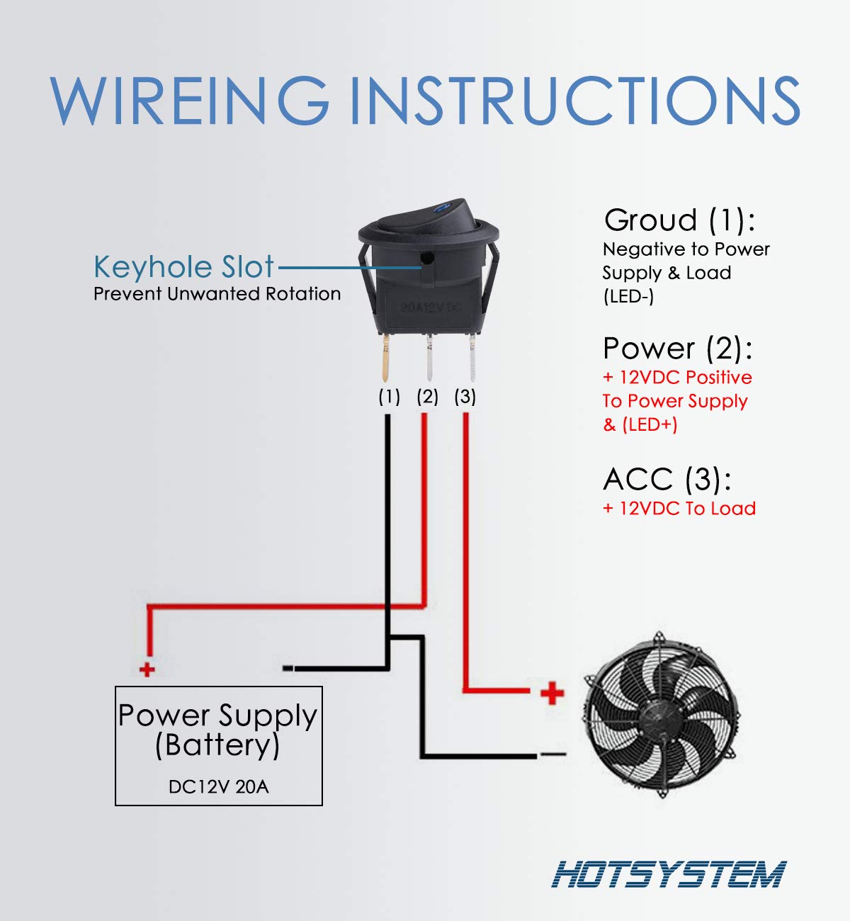
Dc Lighted Switch Wiring Diagram | Wiring Diagram

Two Prong Micro Switch Wiring Diagram - Complete Wiring ...

Closeup of skeleton hand model

12V Electronic 4 terminal

How Do You Wire A Micro Switch Diagram? | Unionwell Switch
Micro Switch Wiring Diagram Fe290

Club Car Micro Switch Wiring Diagram - Wiring Diagram

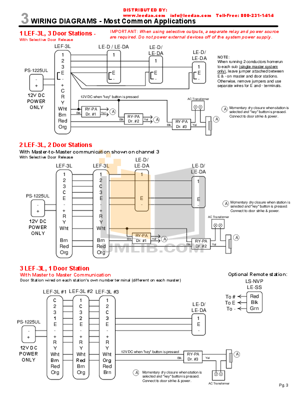
Wiring Diagrams
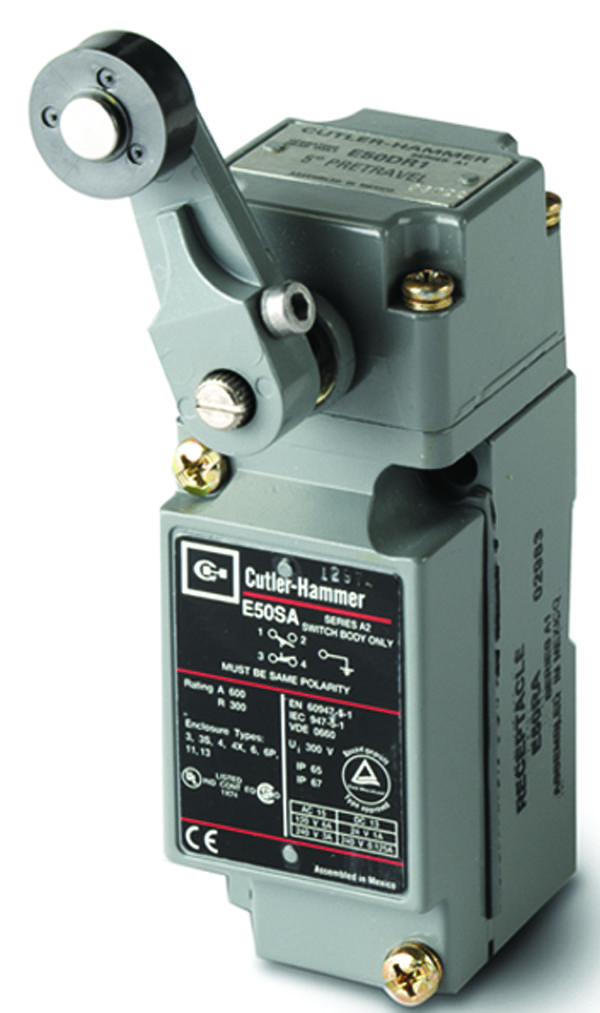
E50AR1 - Eaton Cutler Hammer - Interruptor de Fin de ...

12 volt LED flasher unit

Wiring In A Micro Switch Practical Ansul System Wiring ...
CNC Plasma

Spdt Micro Switch Wiring Diagram Amico - Complete Wiring ...

Club Car Micro Switch Wiring Diagram Free Picture - Wiring ...

Micro Switch No Nc Wiring Diagram - Wiring Diagram

Wiring Diagram For Micro Switch Tap
Micro Switch Wiring Diagram For Nitrou - Wiring Diagram

57 Club Car Micro Switch Wiring Diagram - Wiring Diagram ...

Example of How to Use a Micro Switch | Electronic circuit ...

A shot from our Touriga National Harvest 2017. My brother, the vineyard manager, displaying his product.

MicroSwitch

Wiring diagram • Custom Billet Buttons
Micro Switch Wiring Diagram Fe290

Club Car Micro Switch Wiring Diagram Free Picture - Wiring ...

Wiring In A Micro Switch Creative Honeywell, Limit Switch ...

Micro Switch G2 user guide. : Aeotec Help Desk
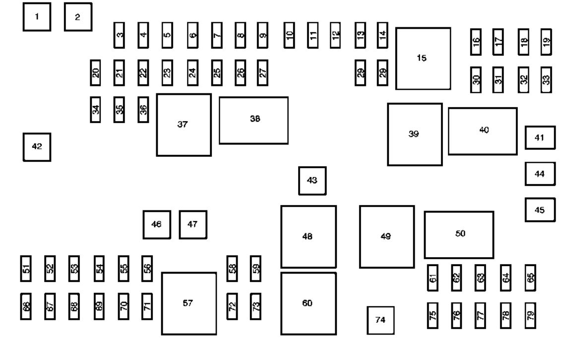
Chevrolet Express (2010 - 2015) - fuse box diagram - Auto ...
Led Arcade Button Wiring Diagram - CINTAJUMIESHAHRIL

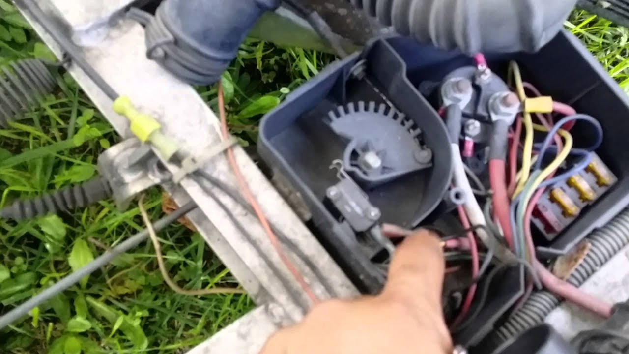
How to Wire up a Micro Switch - YouTube

Club Car Micro Switch Wiring Diagram Free Picture - Wiring ...

Automatic Intruder Alarm Circuit Diagram - The Circuit
How to Use an External Limit Switch with a Linear Actuator?

Ansul System Typical Wiring Diagram | Online Wiring Diagram

41 Ansul Micro Switch Wiring Diagram - Wiring Diagram ...

Wiring In A Micro Switch Perfect Wiring Diagram, Kitchen ...
Ansul Wiring Diagram - Wiring Diagram Networks
Club Car Micro Switch Wiring Diagram Free Picture - Wiring ...
Microswitch | FRC Electrical Bible


Comments
Post a Comment