39 engine cylinder diagram
Mazda Protégé and Cars 1990-1998 and Ford Probe 1993-1997 Firing Orders Repair Guide. Find out how to access AutoZone's Firing Orders Repair Guide for Mazda 323, MX-3, 626, MX-6, Millenia, Protégé 1990-1998 and Ford Probe 1993-1997. Read More. The piston is a solid cylinder of metal, which moves up and down in the cylinder of the engine block. Its purpose is to transfer force from expanding gas in the cylinder to the crankshaft. Piston Pin ( wrist pin ) The piston pin allows the piston to swivel on the connecting rod. The piston pin fits through the hole in the piston and the ...
January 15, 2021 - 4 6 liter ford engine cylinder diagram 4 6l v8 ford firing order ricks free auto repair advice automotive repair tips and how to 4 6 liter ford engine firing order diagram wiring diagram schema mile energy mile energy atmosphereconcept it 4 6 liter ford engine firing order diagram wiring diagram ...
Engine cylinder diagram
Connect the number 1 Firing Terminal to the first Cylinder. Link the number one firing terminal with the first cylinder on the engine. But, this is the first cylinder in the spark plug firing order. This cylinder can be the first or second on the block. In most cases, it will have a marking but if it doesn't have, consult your owner's manual. Download scientific diagram | The heat balance (Q) of the air in the diesel engine combustion chamber (integral characteristic) (ambient temperature – -20°C, crankshaft rotation speed – 100 ... March 6, 2011 - the location of the number one cylinder is important because it is the first cylinder in the engine firing order. the fir
Engine cylinder diagram. Video: Land Rover Engines: Cylinder Numbers & Firing Order Watch, Doug, our Land Rover Master Technician, as he explains how the cylinders are numbered on various North American Spec Land Rover engines, and their respective firing orders. The EJ25 engine used the same aluminum cylinder block with dry cast-iron sleeves applied to the EJ20 engine.T he difference is evident between the EJ20 and EJ25 since the latter has a bigger cylinder bore from 92 mm to 99.5 mm, a longer piston stroke from 75 mm to 79 mm, and a lower compression height from 30.7 to 32. 7 mm. A turning moment diagram for a multi-cylinder engine is shown by a wavy curve in Fig. 16.4. The horizontal line AG represents the mean torque line. Let a1, a3, a5 be the areas above the mean torque line and a2, a4 and a6 be the areas below the mean torque line. These areas represent For gas engines, this means spark plug operation order. For diesel engines, it means the order of when fuel is injected into each cylinder. Firing order affects engine vibration, sound, and power output. It also heavily influences how the crankshaft is designed. There are a number of common firing orders depending on the type of engine.
The 3.6L engine had some moderate revisions in 2016. Apart from that, it's been virtually the same since debuting in 2010 and has become well-known as an FCA signature. Pentastar V6 Specs. The Pentastar is a 60-degree V6 engine, with a cast aluminum cylinder block and heads. It has dual overhead cams with four valves per cylinder (24 valves ... Engine wiring lucas ignition switch wiring diagram diagrams engine. In mini cars equipped with small power starter the ignition switch start position is used to control the starter solenoid switch directly as shown in the picture below. Finding Cylinder No. 1. Make sure you know exactly where cylinder No. 1 is. Before timing the ignition, you need numbers. These numbers can be acquired through aftermarket repair manuals, manufacturer repair manuals, and reputable Internet sources, and from the car's emission labels. Before even picking up a tool, know what RPM the engine is ... 4.6L & 5.4L Cylinder Diagram. Cylinder Numbers, Bank 1 & Bank 2 Location. Diagnostic Trouble Codes (DTC) often identify which cylinder or engine "bank" is ...
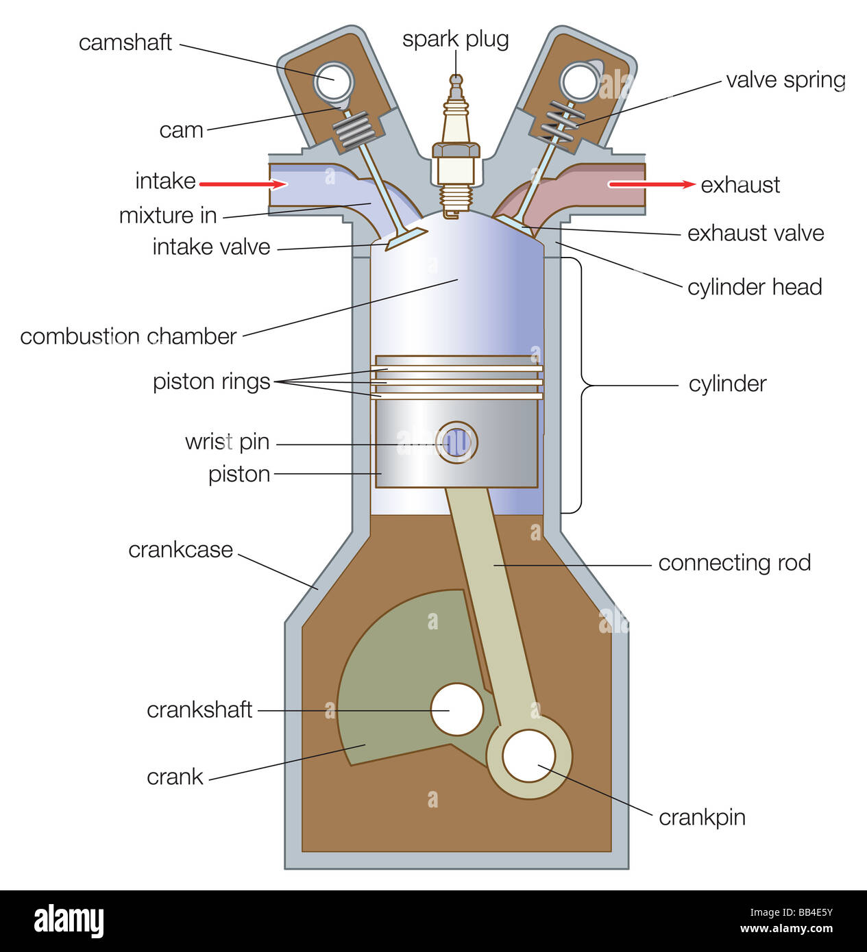
April 5, 2000 - The engine is timed so that only one cylinder receives a spark from the distributor at a time. This approach provides maximum smoothness. We'll look at how your car's engine starts, cools and circulates air in the next section. ... This diagram shows details of how a cooling system and the ... Dec 16, 2021 · What is Engine Blow-By? Engine blow-by is compressed air and fuel in the cylinder combustion chamber going through the piston rings into the crankcase ventilation, usually due to worn piston rings, worn pistons, or a damaged cylinder wall. Internal combustion engines operate through the ignition of air and fuel. August 30, 2021 - Refer to the diagram to locate where they reside on your engine. Engine Block – This is the very core of the engine. Often made of aluminum or iron, it has several holes to contain the cylinders as well as provide water and oil flow paths to cool and lubricate the engine. The inner surface of the cylinder is formed from either a thin metallic liner (also called "sleeve") or a surface coating applied to the engine block. A piston is seated inside each cylinder by several metal piston rings, which also provide seals for compression and the lubricating oil.
Types of Engine Valves: Valve Timing Diagram & Valve ...
15. Boost pressure sensor. The boost pressure sensor measures the boost pressure in the intake boost pipes. You do only have this sensor if your car is equipped with a turbo or supercharger. The boost pressure sensors are often cheap and can be easily replaced on most car models.
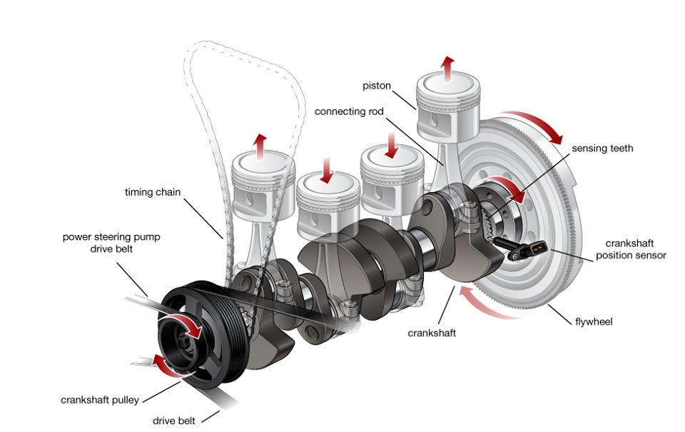
Schematic representation of the engine with multi-cylinders ...
J35Z 3.5L V6 Engine. Honda J35Z engines - also known as the Earth Dreams 3.5L engine - were made from 2006-2014. Specific updates from the J35A engine depend on each variant within the J35Z family of engines. However, one main difference is the use of Variable Cylinder Management (VCM). One of the J35A engines did use this technology, too.

91 Piston Diagram Stock Photos, Pictures & Royalty-Free ...
The firing order of an engine is the sequence the spark plugs fire. On engines with a distributor, the firing order is determined by the routing of the spark plug wires from the distributor cap to the spark plugs in each cylinder. When the piston is at top dead center (TDC) on the compression ...
Typical piston and cylinder arrangement of a gasoline engine ...
series 2 engine cylinder diagram as you such as. Page 2/28. Read Book 3800 Series 2 Engine Cylinder Diagram By searching the title, publisher, or authors of guide you in fact want, you can discover them rapidly. In the house, workplace, or perhaps in your method can be every best place within net Page 3/28. Read Book 3800 Series 2 Engine
What are the basic parts of an engine? - Quora
To understand how the electrical system works, we have drawn a simplified wiring diagram of the engine: We have numbered the cylinders (and combustion chambers) from 1 to 4 going from the front of the engine to the back. The magneto, wires, contact switches, and grounded cylinders produce an electrical circuit, which you have heard about in school.

Basic Car Parts Diagram | Illustrated Diagram Of A BASIC ...
6 Cylinder Diesel Engine Diagram. 6 Cylinder Engine Firing Order Diagram. 2012 Ford Fusion 4 Cylinder Engine Diagram. Ford F150 Cylinder Diagram. Perkins 3 Cylinder Diesel Injector Pump Diagram. 2006 Chevy Silverado Brake Line Diagram Master Cylinder. 31 V6 Engine Diagram. Bmw X5 E53 Engine Diagram.
crankcase | engineering | Britannica
The engine that comes standard on every Ford Maverick model is the 2.5-liter hybrid. That's right, unlike most vehicles with hybrid options, the non-hybrid is the option. In fact, it'll cost you less money to get the hybrid variant of the Ford Maverick. That might be one of its strongest features, as the hybrid engine seems amazing.
Basic Parts of The Car Engine | Sun Auto Service
The Chrysler 2.7 L (ERR) is a 2.7 l (2,703 cc, 167.0 cu.in.) natural aspirated V6 90° four-stroke gasoline engine manufactured by Chrysler from 1997 up to 2010.. The Chrysler 2.7 L V6 engine features an aluminum block and two aluminum cylinder heads with a dual camshaft (DOHC) and four valves per cylinder (24 valves in total).

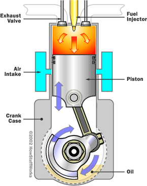
Intake Stroke - an overview | ScienceDirect Topics
The internal combustion engine is a heat engine.It’s working principle is based on the variation of pressure and volume inside the engine’s cylinders. All heat engines are characterized by a pressure-volume diagram, also known as pV diagram, which basically shows the variation of the pressure in the cylinder function of its volume, for a complete engine cycle.

Combustion101-mechanics
Find 4 cylinder diagram stock images in HD and millions of other royalty-free stock photos, illustrations and vectors in the Shutterstock collection. Thousands of new, high-quality pictures added every day.
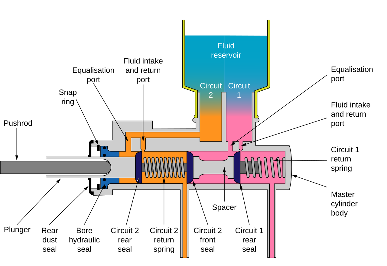
File:Master cylinder diagram.svg - Wikipedia
Example 2.4.6. An indicator diagram taken from a large diesel engine has an area of 400 mm2 and length 50 mm. The indicator spring is such that the scale of the pressure axis is 1 mm = 1 bar. If the cylinder diameter and stroke are both 250 mm and the engine is 4-stroke running at 6 rev/s, find the indicated power if the engine has six cylinders.
Understanding the Cycle - The Diesel Two-Stroke Cycle ...
• Crank Phase Angle: Enter the angular distance between the slave axis of crank system and the position of the crank pin body. For common engine type, it is automatically calculated from the firing order. If the user wants to give the offset value on a cylinder, modify the crank phase angle ...

Single Cylinder Motorcycle Engine Diagram
Also, since there is still such a strong desire for these engines, we thought it best to gather some of the more commonly used specifications for those of you who still sport a Blue Oval under the hood of your ride. Shown to the right we have a diagram illustrating the distributor rotation, cylinder orientation, and firing order.
IC ENGINE: COMPONENTS AND THEIR FUNCTIONS, TYPES AND ...
Turning Moment Diagram for a Multi-cylinder Engine Resultant TMD = sum of turning moment diagrams for the three cylinders. 1stcylinder = high pressure cylinder 2ndcylinder = intermediate cylinder 3rdcylinder = low pressure cylinder Cranks, in case of three cylinders, are usually placed at 120° to each other.
![Components or Parts of IC Engine with its Function [PDF]](https://mechanicalenotes.com/wp-content/uploads/2020/06/basic-parts-of-IC-Engine.png)
Components or Parts of IC Engine with its Function [PDF]
Head camshaft. Additional cylinder head parts. 1. Head Gasket. These are located between the cylinder head and the engine block. A head gasket is bolted on top of the engine housing. These gaskets act as a seal between the cylinder head and the engine block. This prevents the oil and engine coolant from leaking or mixing.
Internal combustion engine Images, Stock Photos & Vectors ...
each cylinder gets its own ignition tower but shares its coil with a companion cylinder. Scooter engine diagram Apr 05, 2000 · The ignition system (Figure 6) produces a high-voltage electrical charge and transmits it to the spark plugs via ignition wires. The charge first flows to a distributor, which you can easily find under the hood of most ...
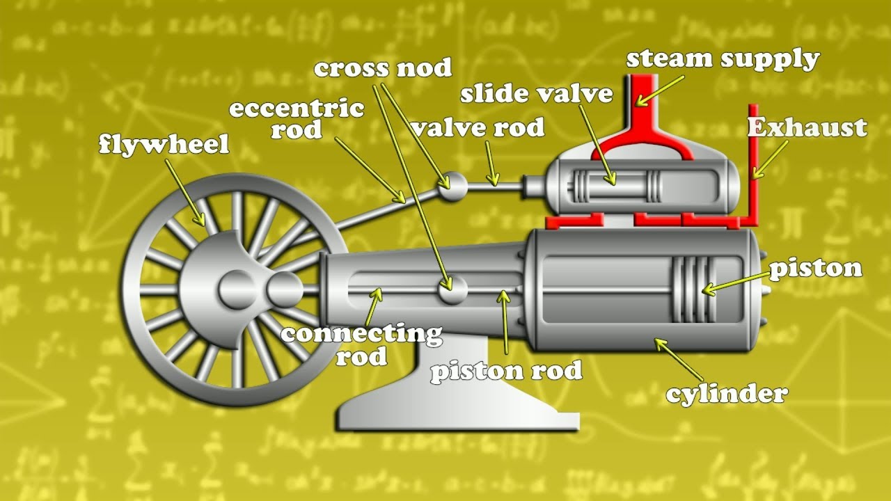
How to works steam engine single cylinder animation
Modular V8 (L, L) - Cylinder Numbers for - Anyone have a diagram or know of a website that shows how the cylinders in a are.Here are a few of top notch 5 4 triton engine firing order diagram photos on the internet. We identified it from reliable source. Its …

File:Inline 6 Cylinder with firing order 1-5-3-6-2-4.gif ...
The vast majority of automotive four-cylinder engines use a straight-four layout: pp. 13–16 (with the exceptions of the flat-four engines produced by Subaru and Porsche) and the layout is also very common in motorcycles and other machinery. Therefore the term "four-cylinder engine" is usually ...

What are the cylinder arrangements? | WapCar
2 Engine Heat Transfer: Impact • Efficiency and Power: Heat transfer in the inlet decrease volumetric efficiency. In the cylinder, heat losses to the wall is a loss of availability. • Exhaust temperature: Heat losses to exhaust influence the turbocharger performance. In- c ylinder and exhaust system heat

BMW F90 M5 Car Blog: The Otto Engine
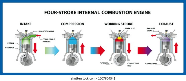
Download scientific diagram | Schematic of a 4-stroke engine from publication: Analysis of a hydrogen fuelled internal combustion engine | In the history of internal combustion engine development, hydrogen has been considered at several phases as a substitute to hydrocarbon-based fuels.

Quotes about Car engine (41 quotes)
Browse 1,915 car engine diagram stock illustrations and vector graphics available royalty-free, or search for internal combustion engine or engine blueprint to find more great stock images and vector art. Newest results internal combustion engine engine blueprint dashboard car engine drawing Corporate Identity, plan, sketch.

Cylinder Block (Automobile)
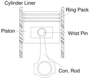
A cylinder liner is a thin metal cylinder-shaped part to be fitted into an engine block to form a cylinder. It is one of the most important functional parts to make up the interior of an engine. The cylinder liner, serving as the inner wall of a cylinder, forms a sliding surface for the piston rings while retaining the lubricant within.

Schematic diagram of the cylinder and the piston in an engine ...
10/07/2020 · Below is the complete diagram of a cylinder block: Types of the engine block. Engine blocks are classified depending on the configurations of the engine. Below are the types of engine block: V engine: the v engine is the popular type of cylinder available on most vehicles today. Starting from the Cadillac v16 to classic v8s even up to tiny v4s used on …
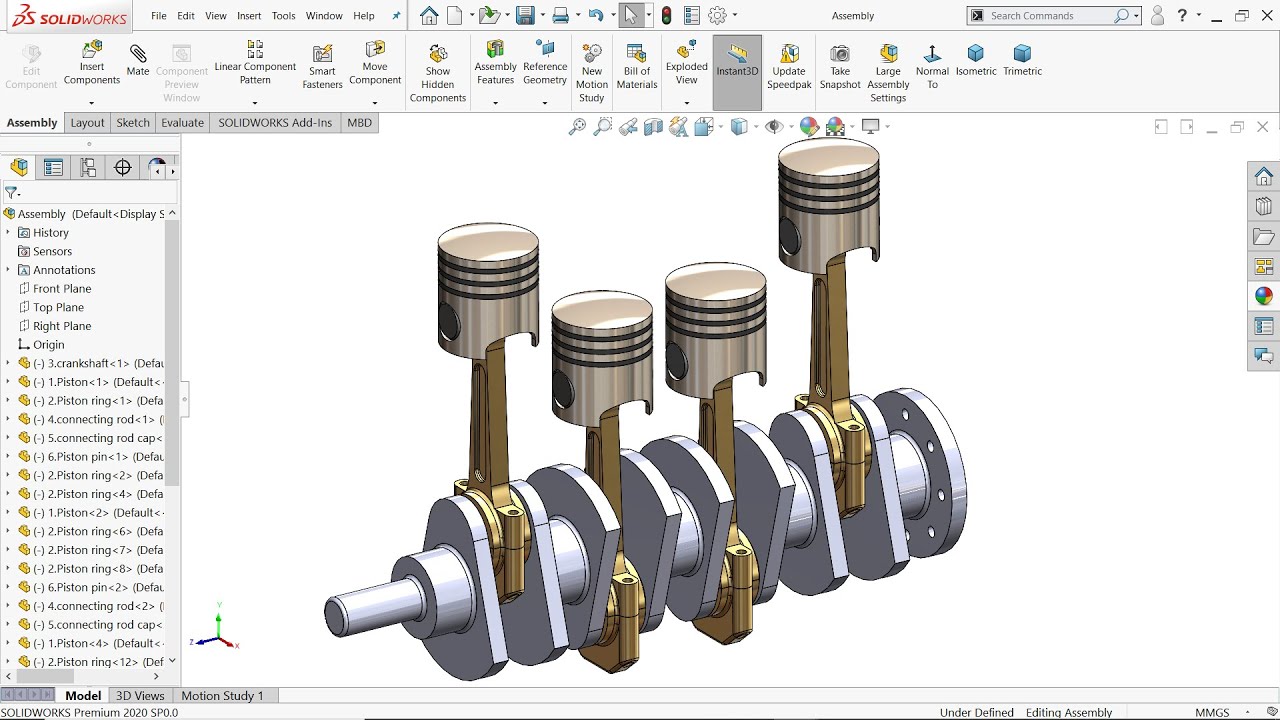
Four Cylinder engine in Solidworks
The engine block and cylinder heads were cast iron. Ford used cast iron for the engine blocks and cylinder heads throughout the production of the 302 in Fox Body and SN95 Mustangs. 1980-1981 Fox Body Mustangs. In 1980, Ford introduced a new version of its small-block V-8 engine. It was a 4.2-liter or 255 cubic inch variant of the 302 which had ...
Ic engine
One layout has a flat/boxer engine at its center and adds an additional opposed-piston to each end so there are two pistons per cylinder on each side. ... W engines have the cylinders in a configuration in which the cylinder banks resemble the letter W, in the same way those of a V engine resemble ...

How to remove a marine diesel cylinder head step by step
In a spark ignition (e.g. gasoline/petrol) engine, the firing order corresponds to the order in which the spark plugs are operated. In a diesel engine, the firing order corresponds to the order in which fuel is injected into each cylinder. Four-stroke engines must also time the valve openings ...
![Multi-cylinder LD engine set up [94]. | Download Scientific ...](https://www.researchgate.net/profile/Ganesh-Duraisamy-2/publication/264426023/figure/fig2/AS:614362943324187@1523486948792/Multi-cylinder-LD-engine-set-up-94.png)
Multi-cylinder LD engine set up [94]. | Download Scientific ...
Cylinder #1 is now on the compression stroke, cylinder #3 is on the intake stroke (i) and cylinder #4 is, as expected, on the exhaust stroke (e) to expel exhaust gases produced from the power stroke it just completed. See figure 3d.
![Cylinder Block: Diagram, Parts, Types, Functions, Material [PDF]](https://www.theengineerspost.com/wp-content/uploads/2021/07/Different-Types-of-Cylinder-Block-min-e1626707202927.jpg)
Cylinder Block: Diagram, Parts, Types, Functions, Material [PDF]
The valve timing diagram for a four-stroke cycle diesel engine. The following particulars are important for a four-stroke cycle diesel engine regarding the valve timing diagram. The inlet valve opens ar 10-20 degree before TDC and close at 25-40 degree after BDC. The fuel valve opens at 10-15 degree before TDC and close at 15-20 degree after TDC.
Power Cylinder System for Internal Combustion Engines ...
Toyota 22re Engine Diagram - Best Free Wiring Diagram The Toyota 22R is a 24 L 2366 cc 14438 cuin straight-four 4-stroke natural aspirated gasoline engine from Toyota R-family. 1986 Toyota 22rte Re Efi Wiring Diagram. Cylinder bore and piston stroke are 920 mm 362 in and 890 mm 35 in respectively.
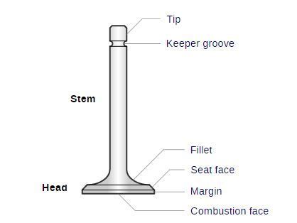
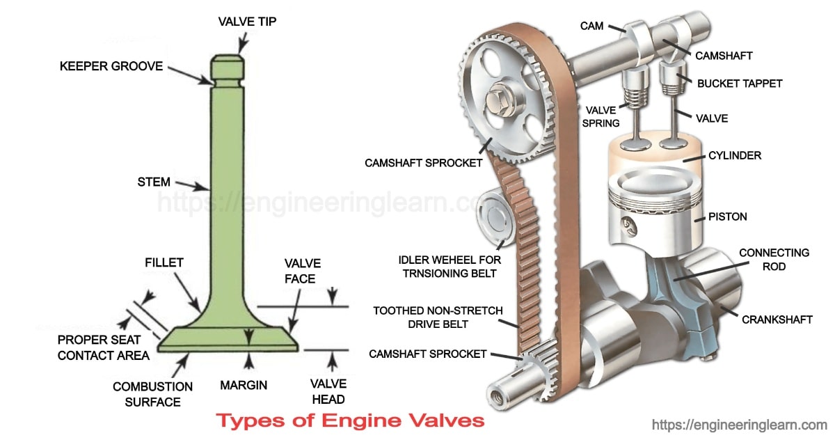
All About Engine Valves
The cylinder block, cylinder head, and crankcase are the three parts that form the foundation and main stationary body of an automobile engine. They serve as support an enclosure for moving parts. The cylinder block may also have a separate crankcase for the crankshaft, which is limited to larger engines, marine, and stationary engines.

What list of basic engine Components? | Internal Combustion ...
Here is a basic wiring diagram showing how to wire a vintage small engine that uses a magneto ignition system with points for the timing. This diagram shows the correct colours up to 1925. Samples of engines like this include the kohler k141 k161 k181 and some k241 engines. Spark wires timing wires ground body ground wires positive batt coils ...
Engines Types Sizes
May 5, 2020 - This final stroke forces the spent gasses/exhaust out of the cylinder. The cycle in now complete and the piston is ready to begin the intake stroke. The below diagram gives a visual representation of how this process works:
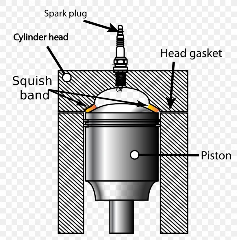
Squish Internal Combustion Engine Cylinder Dead Centre, PNG ...
KA24DE: Engine Basics and Specs. The KA24DE is a 2.4L inline four-cylinder engine that uses an iron cylinder block with an aluminum cylinder head. Part of the reason Nissan used an iron cylinder block was to save money. The engine was intended for use in light trucks and SUVs, so weight saving wasn't a significant concern.
![Cylinder Block: Diagram, Parts, Types, Functions, Material [PDF]](https://www.theengineerspost.com/wp-content/uploads/2020/04/Cylinder-block-1-1-1.png?ezimgfmt=rs:352x347/rscb19/ng:webp/ngcb19)
Cylinder Block: Diagram, Parts, Types, Functions, Material [PDF]
The Toyota 5VZ-FE is a 3.4 L (3,378 cc, 206.14 cu·in) V6, four-stroke cycle water-cooled naturally aspirated internal combustion gasoline engine, manufactured by the Toyota Motor Corporation since 1995 to 2004. The engine was producted on Toyota Motor Manufacturing Alabama. The 5VZ-FE engine has 6 cylinders in a V arrangement at a bank angle of 60° The 5VZ-FE features a cast-iron cylinder ...
What is the layout of an IC engine? - Quora
Oct 25, 2020 · The engine is working in four steps; that’s why this engine type is called a four-stroke engine. The piston goes down, filling the cylinder with an air-fuel mixture from the intake The piston goes up, compressing the air-fuel mixture to a high pressure
![Cylinder Block: Diagram, Parts, Types, Functions, Material [PDF]](https://www.theengineerspost.com/wp-content/uploads/2021/07/V-engine-block-min-4.jpg?ezimgfmt=rs:352x234/rscb19/ng:webp/ngcb19)
Cylinder Block: Diagram, Parts, Types, Functions, Material [PDF]
Download scientific diagram | Schematic diagram of the cylinder and the piston in an engine. from publication: Fault detection in an engine by fusing information from multivibration sensors | Fault detection based on the vibration signal of an engine is an effective non-disassembly method for ...

2,075 Car Engine Diagram Stock Photos, Pictures & Royalty ...
October 5, 2003 - A piston is a cylindrical engine component that slides back and forth in the cylinder bore by forces produced during the combustion process. The piston acts as a movable end of the combustion chamber. The stationary end of the combustion chamber is the cylinder head.

Solidworks tutorial Design of Single cylinder Engine Part 1
Access 130+ million publications and connect with 20+ million researchers. Join for free and gain visibility by uploading your research.
Reciprocating Piston Engines
engine cylinder diagram book review, free download


Comments
Post a Comment