39 Esc Wiring Diagram
Arduino Brushless Motor Control Tutorial | ESC - How To Mechatronics Arduino Brushless Motor Control - Circuit Diagram. Here's the circuit diagram for this example. In addition to the ESC we will just use a simple potentiometer for controlling the motor speed. Need a MOA with dual ESC and BEC wiring diagram | Forum I remembered there's one wiring diagram in XR10 forum sticky thread posted by Harley, but that diagram was no longer available now. Here's the basic wiring diagram for a dual ESCs with BEC on XR10.
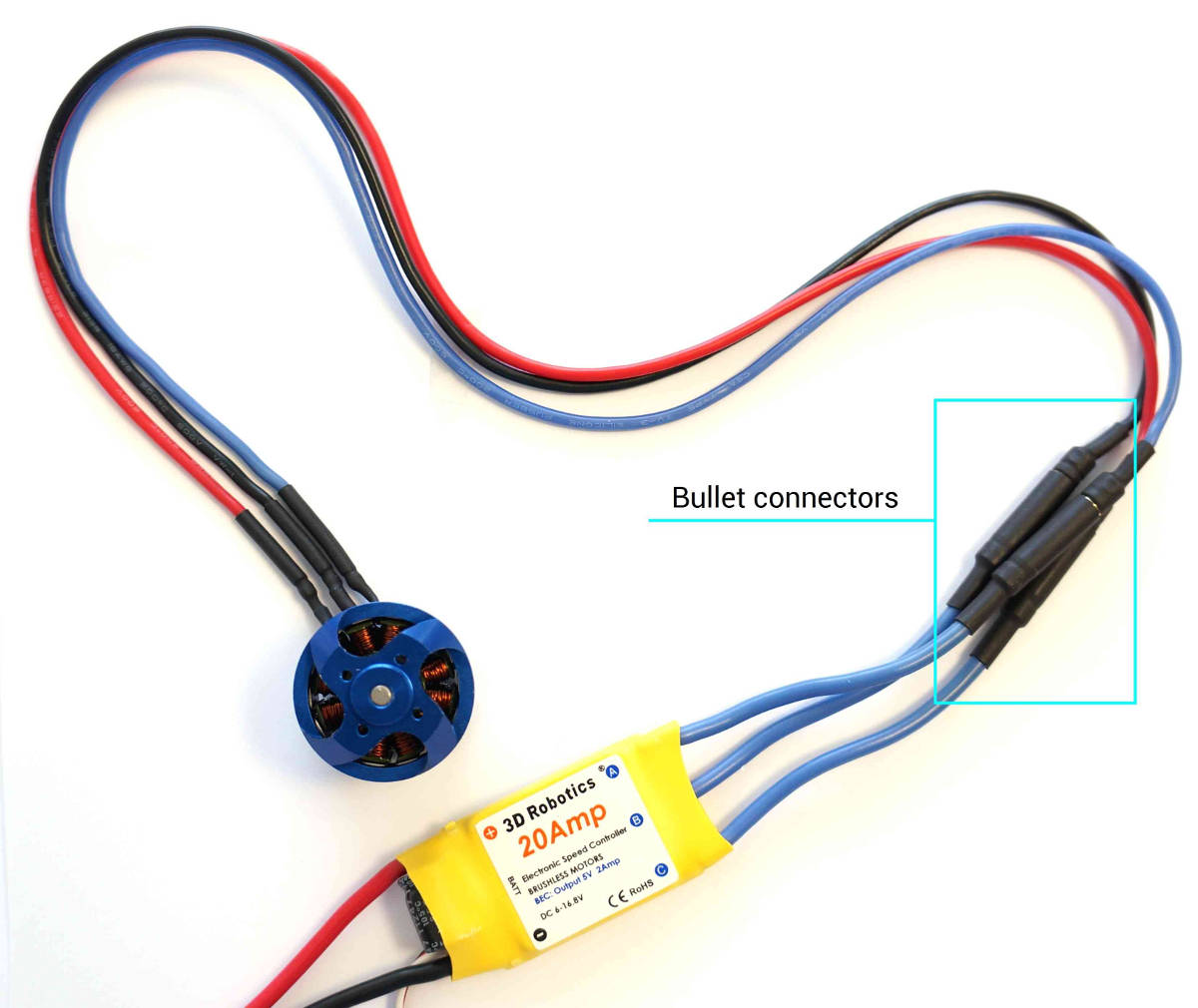
Spektrum FIRMA SMART ESC Series Spektrum FIRMA SMART ... Wiring Diagram Motor Leads** **160A ESC features female bullet connectors directly on the ESC case Battery Leads Steering Servo* Throttle Connection Receiver * Motor* Battery* Cooling Fan Programming Port LED Indicators Switch Board Set Button On/Off Button * Not Included. 6 Throttle Signal SMART Throttle: The Spektrum Firma™ ESC is compatible with SMART …
Esc wiring diagram
Electronic Speed Control (ESC) : Circuit, Types, Working & Its... An ESC or electronic speed control mainly follows a speed reference signal to change the speed of a switching network of field-effect transistors. The motor speed can be changed by changing the... Sensorless BLDC motor control with Arduino - DIY ESC Breadboard. Jumper wires. Sensorless BLDC motor control with Arduino circuit: Project circuit schematic is shown below. Note that all grounded terminals are connected together. ESC WIRING DIAGRAM - Auto Electrical Wiring Diagram Diagram - easywiring May 29, 20214 in 1 esc wiring diagram. A 4in1 esc is more convenient to use as there is less messy wiring as the powering of each esc is done internally on the board.
Esc wiring diagram. 1 pages Wiring Diagram for Frigidaire FED300ESC Cooktop FED300ESC. Wiring Diagram. Document: Wiring Diagram, File Type: PDF. Count of Pages: 1. Download FED300ESC Manual (1 pages). Residential Electrical Wiring Diagrams » Home » Wiring Diagrams » Residential Electrical Wiring: Guide to Home Wiring » Need Summary: Residential Electric Wiring Diagrams are an important tool for installing and testing home... ESC Wiring and Setup Instructions - Petit RC 1. Ensure ESC is wired properly using the diagram and steps above. Connection Diagram & Installation. 1. Connect the speed control to the receiver position (channel 2). 2. Connect power wire... Tricopter ESC wiring diagram - RC Groups | Forum I would appreciate some help with a wiring diagram if anyone has one or can give me a reasonable description of what to do. Also, if you have used this ESC, what program settings have you used and how have you done the calibration?
PDF Wiring Diagram Book WIRING DIAGRAM A wiring diagram shows, as closely as possible, the actual location of all Wiring Diagram. This symbol denotes the coil function, provided by a solid-state control module, 30 VA... Universal ESC Circuit for BLDC and Alternator motors - Homemade... An ESC or electronic speed controller is an electronic circuit which is normally used for operating and controlling a BLDC 3-phase motor. BLDC motor stands for brushless DC motor which clearly states... Drone Esc Wiring Diagram Extending the ESC wires on the motor side of the ESC will not cause destruction of the ESC. Mamba F405 4in1 40A ESC - Unbox, Review, Wiring Diagram Link Pembelian : Diatone Mamba F405 mini... Ford Wiring Diagrams Free Download | Carmanualshub.com Ford Wiring Diagrams. By Michael | December 14, 2018. 10 Comments. Here are wiring diagrams for Ford Escort, F-series, Fiesta, Focus, Mustang, Ranger, Kuga and Many other's.
Automatic Street Light Controller Circuit Using Relays and LDR 09.03.2012 · Description. The circuit diagram present here is that of a street light that automatically switches ON when the night falls and turns OFF when the sun rises.In fact you can this circuit for implementing any type of automatic night light. The circuit uses a Light Dependent Resistor (LDR) to sense the light .When there is light the resistance of LDR will be low. Connect ESCs and Motors — Copter documentation NAVIO2 (Linux based) Wiring QuickStart. ESCs and Motors. Motor order diagrams. Testing motor spin directions. Checking the motor numbering with the Mission Planner Motor test. Ezrun MAX 8 ESC + Program card (Free) - HOBBYWING North ... External Cappack Wiring Diagram (as shown above). Connect a cappack to the ESC input end and ensure red/positive (+) to red/positive (+), black/negative (-) to black/negative (-). A. The vehicle weighs really heavy, the total weight (battery, ESC, motor, steering servo and etc. included) exceeds 7KG, for example, CEG-GST. B. The vehicle weighs ... 4 in 1 ESC Wiring & Set Up - YouTube How To Flash ESCs With Arduino Nano.
Motor to esc connection - Multirotors - ArduPilot Discourse
How to bind Frsky Receivers to Taranis ... - Oscar Liang 29.03.2019 · I recommend wiring the receiver to your flight controller first, as this is the easiest way to do. Otherwise you can also power your receiver with a 5V power source. Here is an example wiring diagram. For binding, SBUS and Smart Port are not necessary, but it’s fine to leave them connected if you want. All you need are the 5V and ground wires. Binding Frsky RX …
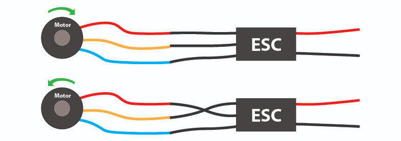
ESC to motor connection guide - how to reverse your motor ...
Racerstar 4 In 1 Esc Wiring Diagram RacerStar 4 in 1 ESC Wiring - HGLRC F3V4 Wiring - Cyclone FPV. CycloneFPV. Today I hope to clear up any confusion I have created in wiring a 4 in 1 ESC to your motors and flight controller.
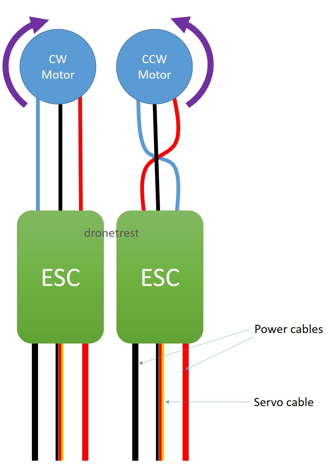
Electric Flight Wiring
Bec Esc Wiring Diagram Disable red wire on ESC for external BEC install. h2oman210. görünümler 54 B10 yıl önce. Pilots constantly ask me "DrainMan how do I wire a 4 in 1 ESC" I know how to do single ESC's but I really...

Dual ESC and 4WS - R/C Tech Forums
Illustration 27 - Esc Wiring Diagram; Stage 9 - Esc... | ManualsLib Neptronic SKD Series Manual Online: illustration 27 - esc wiring diagram, Stage 9 - Esc Device, Electrical Supply, And Control Connections. Diagram to connect all the components to the ESC.
Discussion PowerFLY Mosquito ESC wiring - RC Groups
MAX/SNSC 2.0 BLE to ESC Wiring Diagram (Retail / Rental) | Forum I saw your diagram on Discord. I had tried using the TX/RX of the dashboard and the BMS a few weeks ago, which showed data but couldn't get it to program.

How To Connect Quadcopter Motors and ESC
PDF Electrical wiring diagram This wiring diagram manual has been prepared to provide information on the electrical system of the 2007 CAMRY. Applicable models: GSV40 Series ACV40 Series. Refer to the following manuals for...

Bait Boat wiring - Project Guidance - Arduino Forum
Toyota Full Models 2006-2019 Electrical Wiring Diagram CD1_Online Type of document: Electrical Wiring Diagram Models List: TOYOTA 2006 4Runner Electrical Wiring Land Cruiser Electrical Wiring Diagram (EM0010U) TOYOTA 2006 Prius Electrical Wiring Diagram...
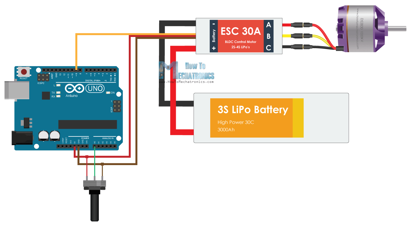
Arduino Brushless Motor Control Tutorial | ESC | BLDC - How ...
ESC Programming on Arduino (Hobbyking ESC) : 4 Steps - Instructables * ESC means Electronic Speed control * The ESC has a 5v(not used), GND and Signal Pin like a Servo Thats why it It is important, that you DON'T connect the red wire to your 5v Port, because it...
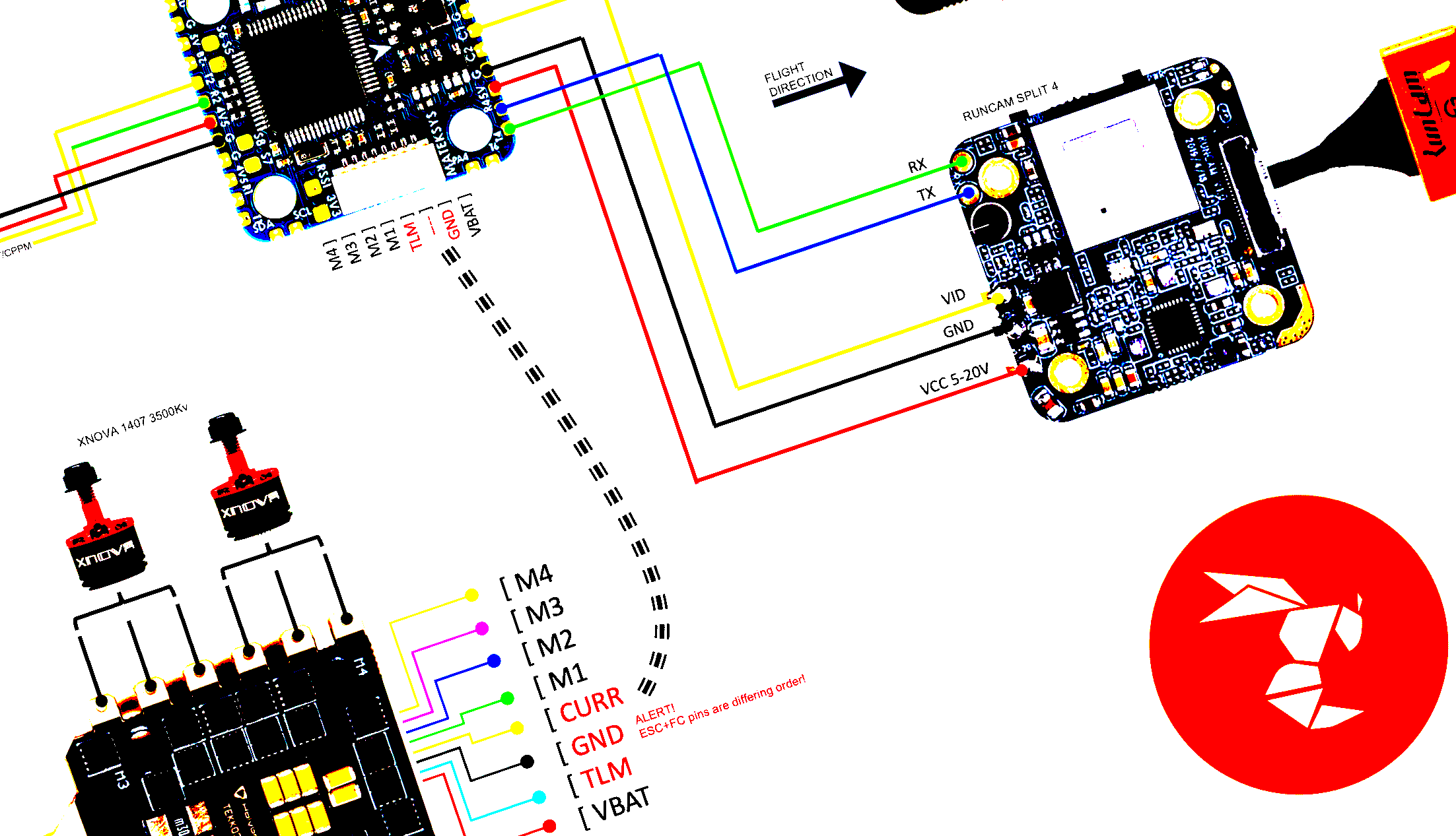
Wiring a Matek F722-MiniSE to Runcam Split 4, Matek VTX-Mini ...
Racerstar 4 In 1 Esc Wiring Diagram RacerStar 4 in 1 ESC Wiring - HGLRC F3V4 Wiring - Cyclone FPV. Today I hope to clear up any confusion I have created in wiring a 4 in 1 ESC to your motors and flight controller.

Where does each Colored Motor Wire go on the ESC? – MBoards
Wiring Diagram With Water Cooling Enclosure Wiring Diagram: "Close (esc)". FLIPSKY Mini FSESC6.7 70A base on VESC6.6 With Aluminum Anodized Heat Sink. CONNECTION DIAGRAM: Features: ◆ STM32F4 32Bit ARM micro-controller...
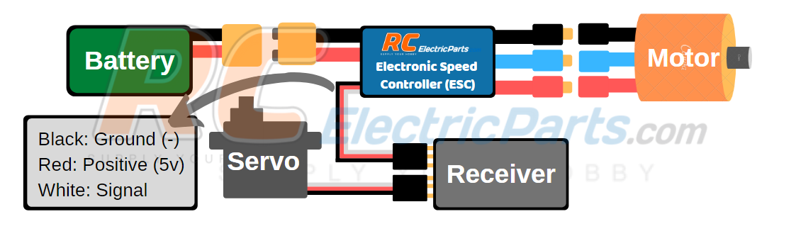
ESC User Guide - RCElectricParts.com
Electrical - ESC Wiring for 12 Pin Flat | Expandas Downunder 11 Dec 2014 — Useful info there with basic wiring diagram. As to using a resettable circuit breaker for the feed I was advised by a credited installer ...10 posts · Ok here goes. We picked up our new 20.63-1 OB recently. It has ESC braking fitted to it. I ...ESC in 12 pin socket20 posts6 Dec 2016ESC/breakaway wiring7 posts24 Mar 2015More results from expandasdownunder.com
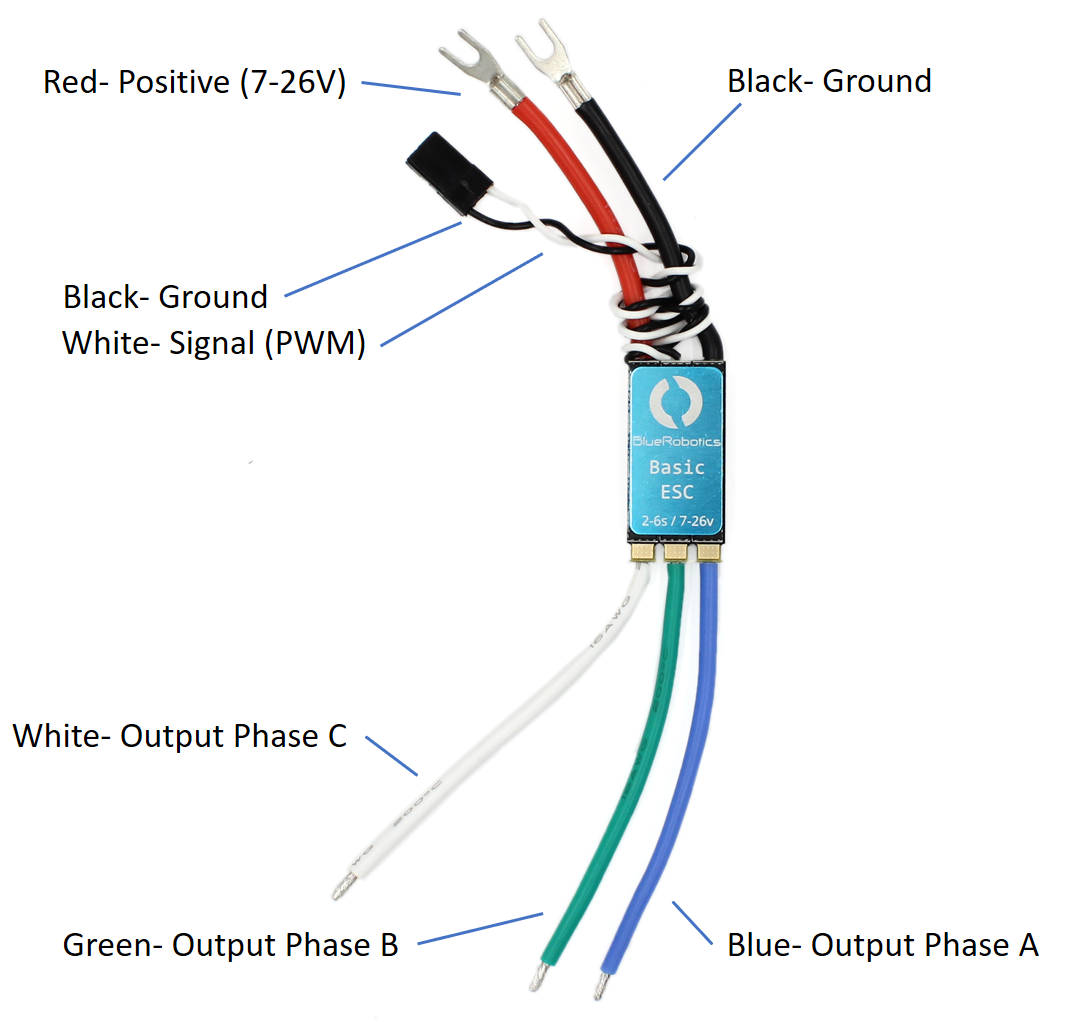
Basic ESC (Electronic Speed Controller) for Thrusters and ...
Wiring diagrams for cars - Technical support for auto electrician repair Car Wiring Diagrams. PORTAL-DIAGNOSTOV. Wiring diagrams, location of elements, decoding fuses.

Electronic Speed Controllers - Robotic Legends
48V Electric Scooter Wiring Diagram and Esc Wiring Diagram... Chinese Scooter Wiring Diagram Elegant | Wiring Diagram Image. 36 Volt Controllers Wiring Diagrams Wiring Diagram Ame. Greentime 24v 250w Brushless Dc Motor Controller E Bike Controller.

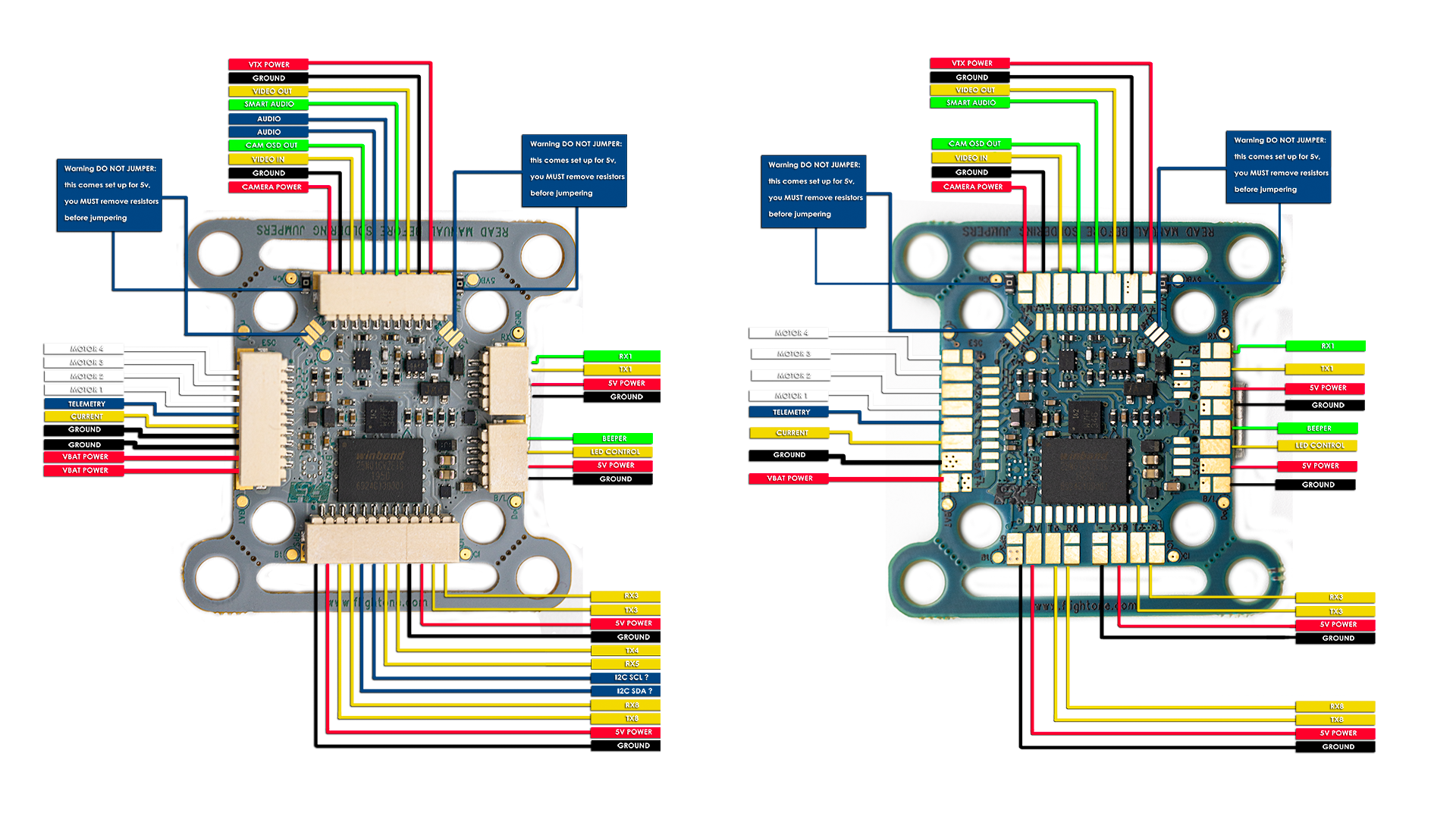
Wiring a Matek F405 to DYS Aria D45A 4 in 1 ESC – flyingsquirrel
PDF Modular Robotic ESC controllers are often used by model hobbyists in radio controller model planes and cars. Therefore, when connecting the ESC with the circuit board, we only connected the PWM signal and...

Malenki Nano Dual ESC and Receiver. Now available in the US from ItGresa Robotics!
Hyundai I10 ABS+ESC wiring diagram - MHH AUTO - Page 1 I need wiring diagram ABS+ESC (MANDO 46PIN connector) from hyundai I10 gasoline engine.

Pdtoweb 30A Mini Brushed ESC Brush Electronic Motor Speed Controller For RC Car
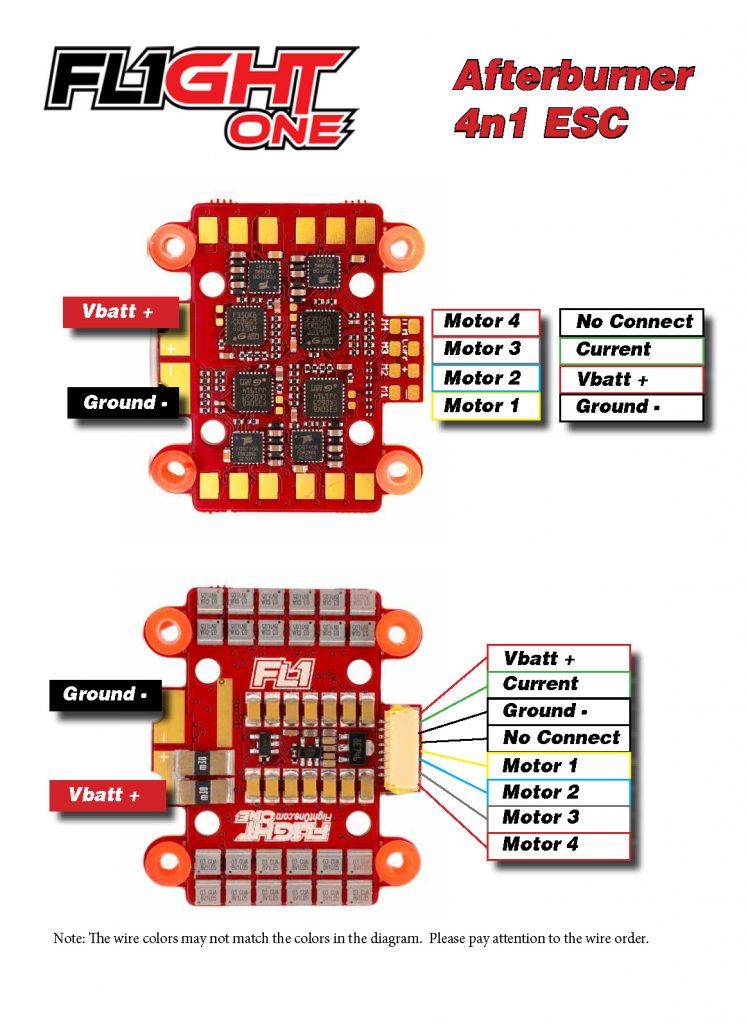
PDF Manual | Onewire ESC Connection Connection Diagram. Basic Setup. 4in1 ESC 45A. Manual. Page 1. Signal 1 - 4 have to be connected to the corresponding FC Motor outputs. The TLM wire has to be connected to an available...
Connect the ESC to the H7 – FlightOne Support
ESC WIRING DIAGRAM - Auto Electrical Wiring Diagram Diagram - easywiring May 29, 20214 in 1 esc wiring diagram. A 4in1 esc is more convenient to use as there is less messy wiring as the powering of each esc is done internally on the board.
Added a wiring diagram to the file section | Details ...
Sensorless BLDC motor control with Arduino - DIY ESC Breadboard. Jumper wires. Sensorless BLDC motor control with Arduino circuit: Project circuit schematic is shown below. Note that all grounded terminals are connected together.
Archived:APM2.x Wiring QuickStart — Copter documentation
Electronic Speed Control (ESC) : Circuit, Types, Working & Its... An ESC or electronic speed control mainly follows a speed reference signal to change the speed of a switching network of field-effect transistors. The motor speed can be changed by changing the...
Afterburner ESC – FlightOne Support
Vector Flight Controller Wiring Diagram Wiring Diagram ...
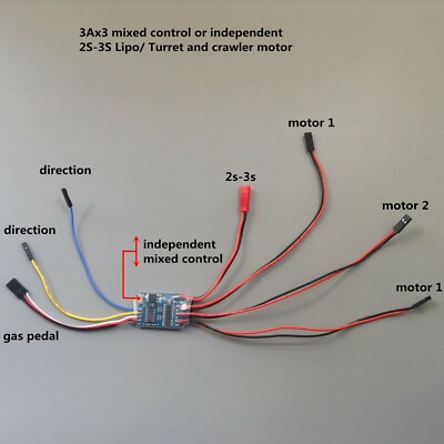
3Ax3 Brushed ESC two-way mixed control Speed Controller RC ...
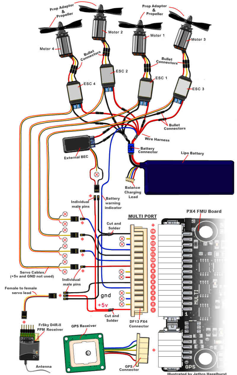
Archived: Installing the PX4FMU on a QuadCopter — Copter ...

Skyline32 / Naze32 Setup wiring guide to motors and ESC ...
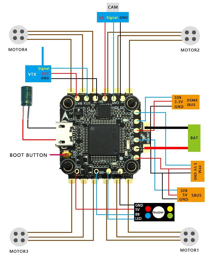
HGLRC Omnibus F438, 33A 4 in 1 ESC & Switchable vTx Stack
QUICK START GUIDE EASY TO USE, SOPHISTICATED ENOUGH TO WIN ...

Transmitter/receiver trouble | Page 4 | Quadcopter Forum

Lumenier QAV250 quadcopter Wiring Diagram for Naze32, Kiss ...
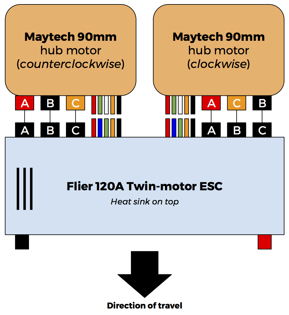
Wiring Maytech Hub Motors to Flier Twin ESC (Electronics ...
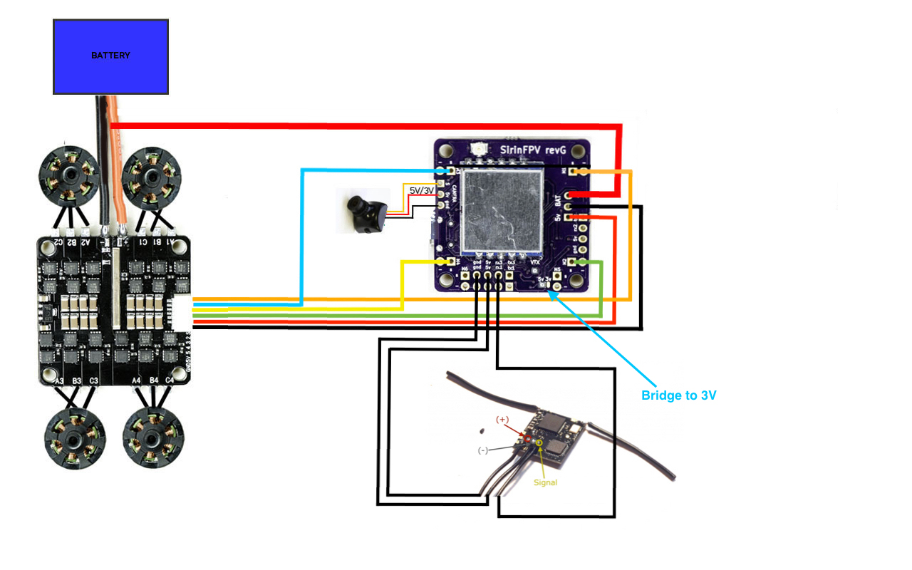
FlexRC Core with SirinFPV V2 wiring diagram – Flex RC
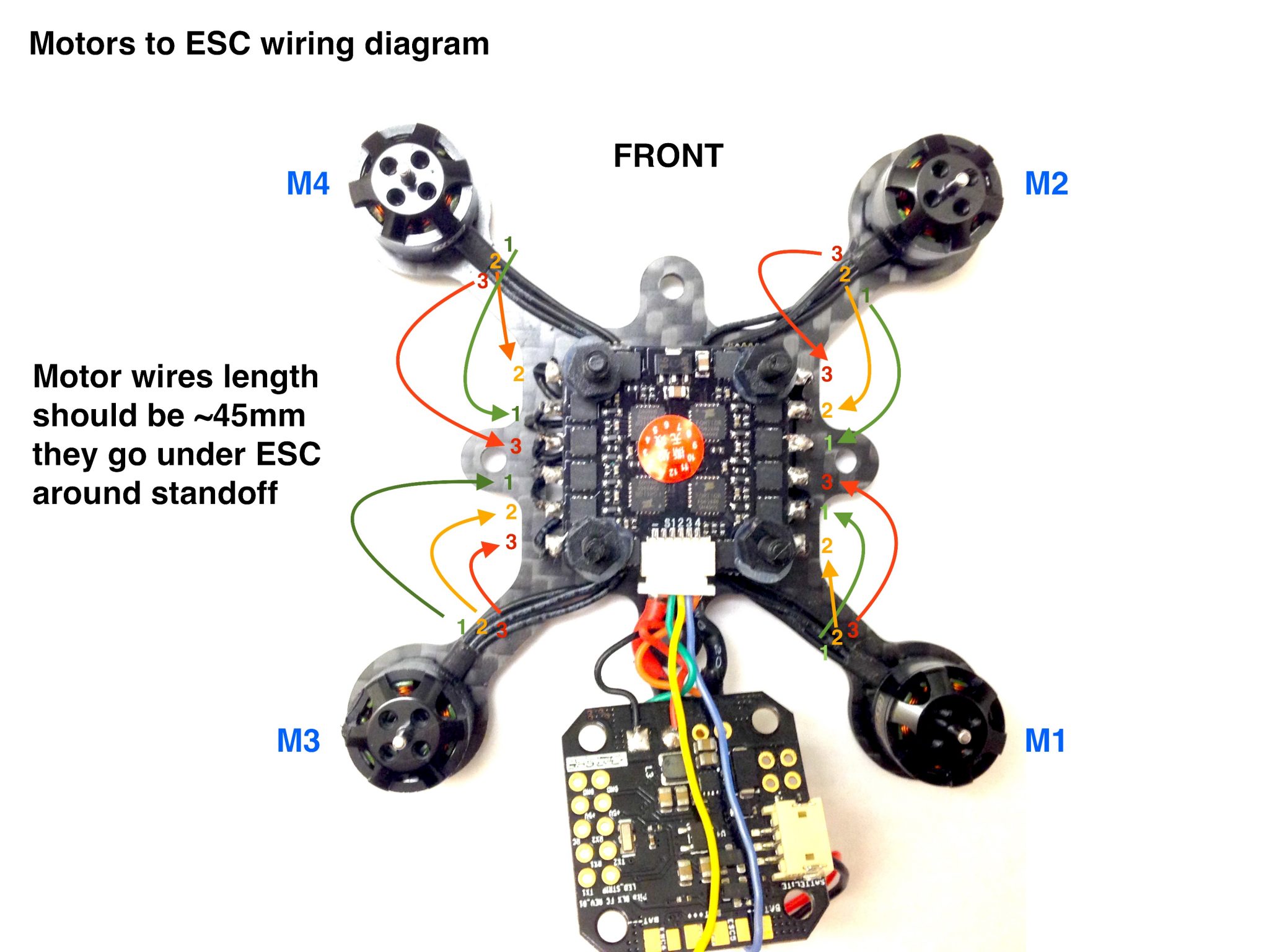
FlexRC Pico Core motors wiring diagram – Flex RC
Twin Brushless Set Up | Model Boats

ESC wiring and connections - KISS documentation

Spektrum SPMXAE1100 Avian 100 Amp Brushless Smart ESC, 3S-6S ...

ESC wiring and connections - KISS documentation
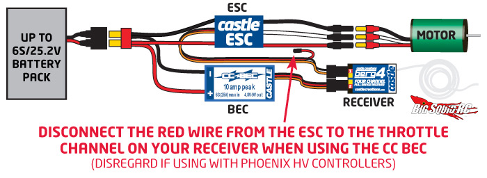
Everybody's Scalin' – Explaining the BEC « Big Squid RC – RC ...

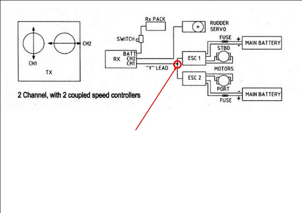
ESC Configurations | Boat wiring, Model airplanes, Airplane ...
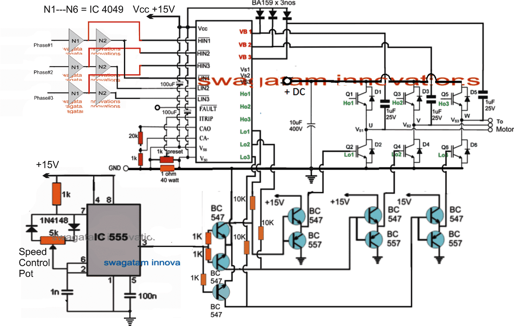
Universal ESC Circuit for BLDC and Alternator motors ...

12+ 48V Electric Scooter Wiring Diagram - Wiring Diagram ...


Comments
Post a Comment