39 fire engine pump diagram
Fire fighting with an 1895 steam fire engine - Inside the ... The vertical engine and pump are located between the boiler and the seat for the firemen. The water pump is direct-coupled to the engine, and the water cylinder has a bore of 7 inches (17.8 cm). It comprises a single outlet connection, inlet and outlet air vessels and five pump valves, three down and two up. Fire Pump Wiring Diagram | Electrical diagram, Electrical ... Fire Pump Wiring Diagram. Find this Pin and more on My Saves by Dilchansada. Big Dog Motorcycle. Motorcycle Wiring. Land Rover Defender. Ford Ranger. Radios. Single Line Diagram. State Diagram.
Put the Pump Chart on the Pump Panel - FireRescue1 Its 3 a.m. and your Engine Company just arrived on scene as part of a second alarm complement at a large warehouse fire. ... The chart will give the pump operator an easy to use visual guide that ...

Fire engine pump diagram
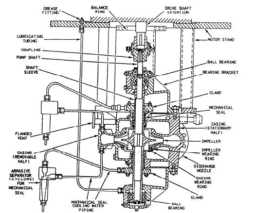
Understanding fire pumps, their applications and sizing Test headers are used to test a fire pump by providing a route to flow water through the pump without sending it thought the rest of the system. Where a test header connection is used, it sits on the discharge side of the fire pump and is sized according to the fire pumps rated size. The table for centrifugal pump sizing is NFPA 20-2016 table 4.27. The Anatomy of a Fire Pump - Fire Apparatus: Fire trucks ... Annual pump testing provides the necessary data to determine continued fire pump capability. The Pump Body. The pump body is the part of the fire pump that controls and directs the flow of water from the inlet side through to the discharge. Within the pump body are three main parts: the intake section, the volute section, and the discharge section. Pump It Up - How Fire Engines Work | HowStuffWorks On this particular fire engine, the pump is located just behind the jumpseat area, where the firefighters sit. An impeller is a rotor-like device that has curved blades. Driven by its own diesel engine, the impeller spins inside the pump at a high rate. When water comes into the pump, it hits the inner part of the impeller and is slung outward.
Fire engine pump diagram. Fire Pump Installation Inspection Checklist.pdf 7. Fire pump and controller, piping, gauges, jockey pump, and other component locations and design are the same as shown on the approved set of plans. 8. Fire pump has name plate. 9. Wire installation to motor, control inner wiring, and jockey pump wiring is correct. 10. PDF Fire Apparatus Pump Operations, Mechanics, and Components ... MCFRS Driver Certification Program Page 1 of 22 Engine - Module 4 Fire Apparatus Pump Operations, Mechanics, and Components Plain Water Operations Centrifugal Pumps Fire apparatus pumps use centrifugal force to deliver water to the fireground. Centrifugal force is an outward force associated with rotation. PDF Installation & Operation Instructions - Firetrol FTA1100 combined automatic and manual diesel engine fire pump controllers are intended for starting and monitoring fire pump diesel engines. They are available for use with 12 or 24 volt negative ground systems using lead acid or Nickel-Cadmium batteries. FTA1100 PDF QUICK RESPONSE Fire Pumps - Types.doc - pdfMachine from ... Various types of fire pumps are used in fire protection systems. Types of fire pumps include: horizontal split case, vertical split case, vertical in-line, vertical turbine, and end suction. These fire pumps may be powered by an electric motor or diesel engine and on rare occasion powered by a steam turbine.
Anatomy of a Fire Pump | Fire Pumps, Fire Suppression ... A fire pumps is made up of three major parts: the speed increaser/pump transmission, the impeller shaft assembly, and the pump body. All play very important roles in the flow of water through the pump and into the discharge hose for firefighting operations. Engines Engine Vibration White Paper; Reference Data. NFPA 20 Information; Diesel Fuel Requirements; ID Your Engine; Product Bulletins; Language Translations; Legacy Products; Certification Information. FM Certificate of Compliance; UL Certificate of Compliance; LPCB Certificates; Quality Management Certificates; Marketing. Upcoming Events; Why Diesel ... fire pump controller wiring diagram - Generator Controllers FIRE PUMP CONTROLLER WIRING DIAGRAM: AUXILIARY DIGITAL OUTPUTS. Connector JB: (5 Poles) NPN Short Circuit Proof Static Auxiliary Outputs. NOTE: the outputs are 'active low' (200mA nominal current) JB-1. ENGINE IS RUNNING. You can connect an external lamp or an auxiliary relay that energizes when the engine is running. JB-2. Simple Steam Engine Diagram - what is boiler types of ... Here are a number of highest rated Simple Steam Engine Diagram pictures upon internet. We identified it from well-behaved source. Its submitted by presidency in the best field. We take on this kind of Simple Steam Engine Diagram graphic could possibly be the most trending subject with we part it in google improvement or facebook.
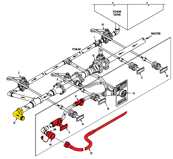
Fire Engine Pump and Plumbing Instructions The diagram below was designed to help you understand the basic functionalty of a fire engine's pump and plumbing. Keep in mind, every fire engine's ... A Guide to the Different Fire Engine Classifications ... Type 3 fire engines carry a minimum of 500 water gallons and have a 150gpm water rate at 250 pounds per square inch of pressure. Type 4 fire engines, on the other hand, have a lower hose power and smaller pump compared with type 3 engines but feature a bigger tank carrying about 750 water gallons. Types 5, 6, and 7 Engines PDF Centrifugal Fire Pump Principles of Operation, Inspection ... Centrifugal Fire Pump Principles of Operation, Inspection Tests and Troubleshooting Guide. F-1031, Section 1000 Revised: 11/21/96 Page 1 of 7 ... about 22 in. Hg/.735 atmospheres in pump, then stop primer and engine. Watch pressure gage; if vacuum drops more than 10 in. Hg/.334 atmospheres in 5 minutes, listen for air leaks around packing ... PDF Fire Pump Systems in NFPA 20 Standard pump need to be diesel engine fire pump. • Jokey pump is used to solve the issue of small pressure drops in the fire installation before the main fire pumps are activated; its flow rate must be min. 1/100 of the flow rate of the main fire pump and its pressure must be min. 1 bar above the pressure of the main fire pump.
Fire Engine Academy
PDF Fire Pump System jockey pump pressure switch , duty/main fire pump and standby pump needs to be synchronized so that all the three pumps will work according to its function. The settings of the three pumps pressure switch are as follows: Note : PS1: Pressure switch-Jockey pump, PS2: Pressure switch-Electric fire pump, PS3: Pressure switch-Diesel engine fire pump
A Guide to Fire Pumps on Ship
Fire Engine Pump and Plumbing Diagram - fire department Fire Engine Pump and Plumbing Diagram This basic diagram was designed to help you understand the functionalty of a fire engine's pump and plumbing. Every fire engine's plumbing is build differently. Keep in mind that your fire engine's pump and plumbing will have a different configuration and may not be equiped with all the valves listed.
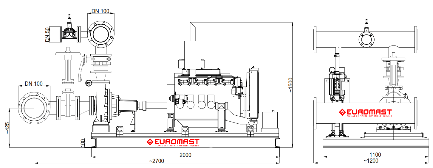
EFP-90-5 - Fire engine pump | Euromast Fire Pumps
PDF Fire Pump Selection Guide - FAMA Centrifugal pump design is the most typical for Fire Pumps and Auxiliary Pumps in modern fire apparatus and its proven design has been used in fire apparatus for well over a century. In a basic centrifugal pump, typically a single casing, water enters through the pump inlet into the center (eye) of the impeller which is spinning on a shaft.

Spray | Nozzle Design | Pressurex-micro Tactile Pressure ...
PDF Fire Pump Drive Engines - Cummins Inc. with CFP, six (6) months from CFP shipment date), the diesel fire pump drivers, manufactured and sold by CFP, shall be free from defects in material and workmanship when used and serviced in accordance with the Operations and Maintenance Manual for the applicable Cummins Fire Pump engine model (the "Exclusive Warranty").
Fire Pump Theory Sugar Land Fire Department Driver/Operator ...
The Anatomy of A Fire Truck - Truck Site The pump panel controls the pressure and flow of all of the hoses on the fire engine Operating the panel efficiently requires years of practice. If the firefighters are spraying one of the preconnects at 360 gallons a minute, they have less than 2 minutes to switch from the fire truck's 500 gallon tank to a hydrant flow source without ...
ELECTRIC/DIESEL FIRE PUMP CHECK LIST
The Ins and Outs of Fire Pumps: Discharges 8 Jan 2016 — More pressure needed generates more noise from the apparatus engine, which is not a good thing on the fireground-especially when the noisiest ...

Fire Pump Types | NFPA
Wiring Diagram of Fire Pump Diesel Engine | PDF | Machines ... of 1 WIRING DIAGRAM OF FIRE PUMP DIESEL ENGINE 1 1 BATTERY -VE 1/2 STOP PUSH BUTTON 2A 02 BATTERY +VE 2A 2A 1 2A 1 2A 2A 2 WATER TWMP 16 A LOT GAUGE 6/2 MECH LOP GAUGE GAUGE FROM AUTO START PANEL FUSE T T T 03 B B 3 START SOLENOID 2 3 + 2B 7/2 11 10 6A 4A 03 1 B+ 4 OVER SPEED KEY TO AMMETER 5A START 5 OVER SPEED 12/2 CHARGING 6A STOP

Pressure Control Auto Manual Circuit । Engineers CommonRoom
PDF Electric/Diesel Fire Pump Check List - Nc fire pump service, arranged to automatically charge at the maximum rate whenever required by the stat of charge of the battery, and arranged to indicate loss of current. For diesel engine driver cooled by a heat exchanger, the cooling water supply is from the discharge of the pump and taken prior to the discharge check valve.
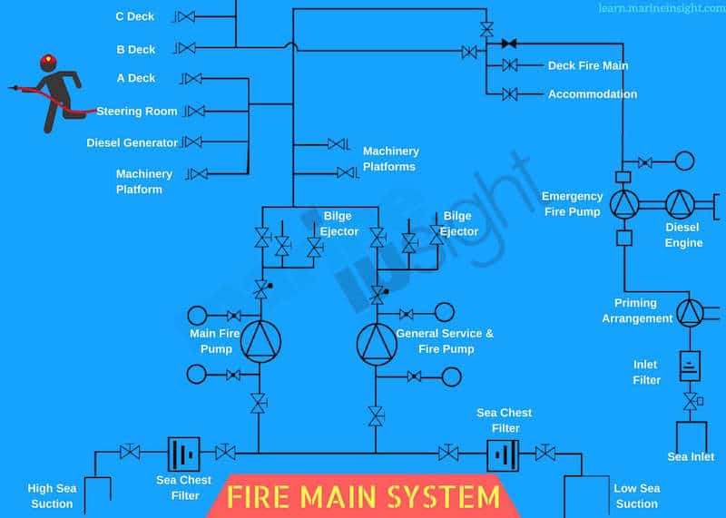
A Guide to Fire Pumps on Ship
Fire Pump Transfer Case - YouTube How the pump and road gear work.
Fire Foam System Configurations: 1-2 Tanks
PDF Operation and Maintenance Instructions Manual pumps useless. The diesel driven fire pump system is pre-ferred by most insurance companies. This manual covers Perkins diesel engines as marketed thru Detroit Diesel Corporation. These engines have been manu-factured with specific options to function integrally with an automatic engine controller for stand-by fire protection ser-vice and to ...

What Are Jockey Pumps and How Do They Work? - Flow Tech News
Fireground Pump Operations: Mastering the Panel - Fire ... The fire is going out, but there may be a better hose, a better nozzle, a better pump pressure, or a better technique to make it go out quicker and make things better for occupants and nozzle crews.
Fire Apparatus Pump Operations, Mechanics, and Components ...
Fire Pumps | Diesel & Electric Fire Pump Manufacturers ... The Flex Series range of pumps brings years of design and manufacturing experience together with true customer benefiting innovation to create a heavy duty pump and gearbox combination that simplifies pump installation and flexibility to the fire apparatus OEM's, while enhancing performance, overall durability, and ease of service for end users.

Firewater System - an overview | ScienceDirect Topics
Engine Wiring Diagram For A 3412 Fire Pump Engine Engine Wiring Diagram For A 3412 Fire Pump Engine. Harness And Wire Electrical Schematic Symbols .. A THIS SCHEMATIC IS FOR THE E AND E ENGINES ELECTRICAL . Cat Pump Tecni 1 . Study on Buildup the Properties of R.C.C. Structures against FireCargado por. This manual has been designed as a guide to operators to aid in starting, stopping and .

12+ Diesel Engine Fire Pump Controller Wiring Diagram ...
Pump It Up - How Fire Engines Work | HowStuffWorks On this particular fire engine, the pump is located just behind the jumpseat area, where the firefighters sit. An impeller is a rotor-like device that has curved blades. Driven by its own diesel engine, the impeller spins inside the pump at a high rate. When water comes into the pump, it hits the inner part of the impeller and is slung outward.

Automatic Fire Pump Priming - Fire Apparatus: Fire trucks ...
The Anatomy of a Fire Pump - Fire Apparatus: Fire trucks ... Annual pump testing provides the necessary data to determine continued fire pump capability. The Pump Body. The pump body is the part of the fire pump that controls and directs the flow of water from the inlet side through to the discharge. Within the pump body are three main parts: the intake section, the volute section, and the discharge section.
Fire Pump Systems | EC&M
Understanding fire pumps, their applications and sizing Test headers are used to test a fire pump by providing a route to flow water through the pump without sending it thought the rest of the system. Where a test header connection is used, it sits on the discharge side of the fire pump and is sized according to the fire pumps rated size. The table for centrifugal pump sizing is NFPA 20-2016 table 4.27.

UL FM Diesel Engine Pump / 10 Bar Submersible Vertical ...
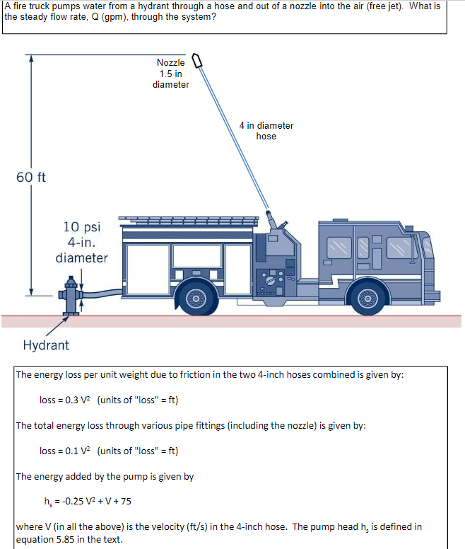
Solved A fire truck pumps water from a hydrant through a ...
Fire Pump Systems | EC&M

Fire Cisterns
CVFD Training – Pump Operations - ppt download

Relief Valves for Centrifugal Pumps According to NFPA 20 ...

WATEROUS - CMU Series Two Stage Fire Pump

WATEROUS - Discharge Relief Valve

Insufficient Maintenance Program & Lack Of Guidance Leads To ...

Diesel Engine Submerged Vertical Turbine Deep Well Long Shaft ...

Put the Pump Chart on the Pump Panel

Fire Pump Accessories | Fire protection, Fire, Pumps
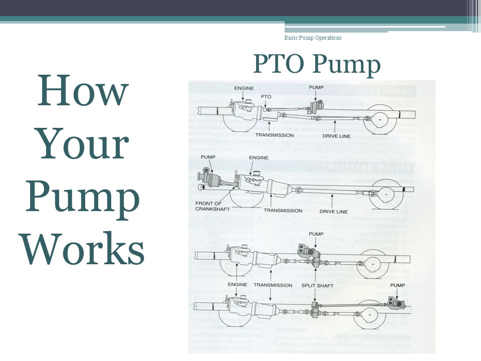
Welcome to Basic Pump Operations ! - ppt download

1500r/Min Fire Fighting Pump Diesel Engine Driven Fire Pump ...

Rural Firefighting University: Fire Pumps - Fire Apparatus ...

Fire Engine Academy
Fire Apparatus Pump Operations, Mechanics, and Components ...

Csepel-Metz TLF 24/50 heavy-duty truck fire hose and the ...

Industrial Packaged Fire Pump Set – NAFFCO – Fire Pump
Construction of Centrifugal Pumps

Electric Jockey Pump with Diesel Fire Pump System (PEDJ 50Hz ...
Why Diesel Engines on Fire Pumps Fail Prematurely
Electronic Foam Proportioning Systems Description ...


Comments
Post a Comment