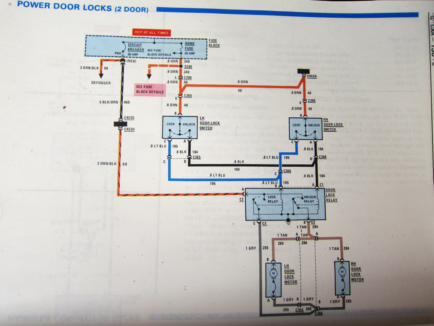
40 door lock relay diagram
Multiplex Door Lock Reference Chart ...... Multiplexed Door Lock Wiring Diagram..... 16. Multiplexed Wiring With 451 Relay Pack or On-Board Relays .21 pages Fuse box diagram and location for the 2011-2020 Nissan Versa. In this video, we show the passenger and engine (power distribution box) fuse box diagrams on a 2011-2020 Nissan Versa. This model is also known as the Nissan Sunny and Nissan Latio, depending on where you are located. We hope this video is helpful, thanks … Continue reading "Nissan Versa Fuse Box Diagram"
when the lock switches are engaged from any of the 3 door lock controls (drivers control, front passengers control and rear hatch control) only the driver's door will lock . I've tested the door lock and unlock relays using a test light probe both the unlock and lock relay are working correctly when the switches are engaged.
Door lock relay diagram
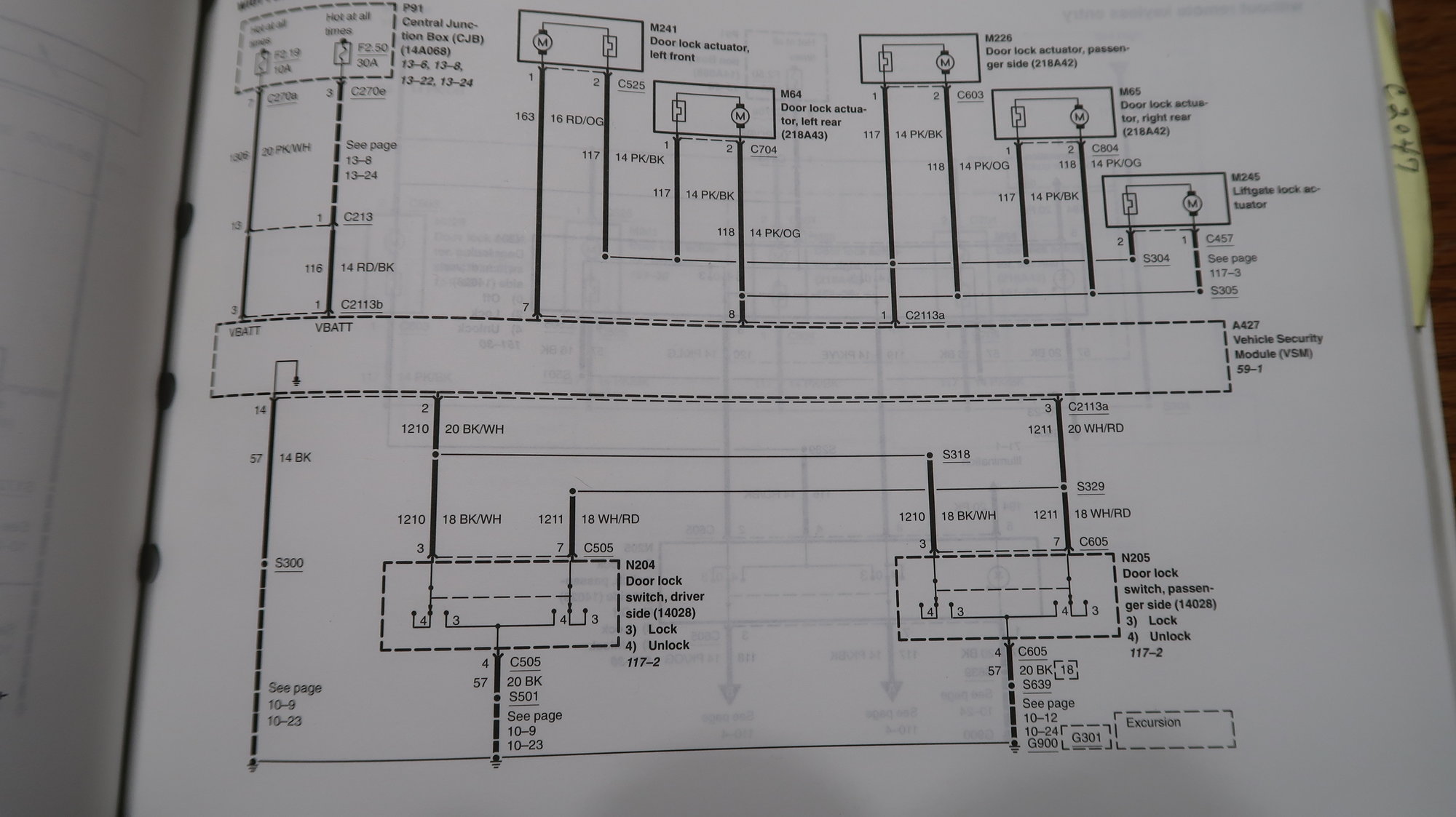
Dodge Journey (2010) - fuse box diagram. Jonathan Yarden Oct 22, 2021 · 5 min. read. In this article you will find a description of fuses and relays Dodge, with photos of block diagrams and their locations. Highlighted the cigarette lighter fuse (as the most popular thing people look for). Get tips on blown fuses, replacing a fuse, and more. The door locks are control by relays. There is a fuse block on the LH side rear floor. (see diagram). There are few relays that controls the door lock on that vehicle. First do a visual inspection of the relays. You can also test the relays as well: The negative terminal of the lock goes back to the Ground (0V) of the 12VDC power supply. Now when the RFID reader reads a RFID card, Rpi will checks if RFID card read is valid, and if yes, would trigger the Relay channel. Now COM will disconnect from NC. In other words, the 12VDC power to the lock is cut off.
Door lock relay diagram. I have an older generation with a base CTM located in the glove box compartment no power door lock relays. My question is where do I tie in the wire coming off of pin 86 (alarm lock output) and pin 85 (alarm unlock output)? Note: This question is assuming I am using the correct relay diagram. If not, please advise. 16+ Car Center Lock Wiring Diagram Car Diagram in 2020 . Best Relay Wiring Diagram 5 Pin Wiring Diagram Bosch 5 Pin . 12+ Chapman Car Alarm Wiring Diagram Car Diagram in 2020 . DEED OF SALE MOTOR VEHICLE FORMAT FILESishare sale . Great Wiring Diagram For Horn Relay HORN RELAY Simple . TOYOTA 58806 Маtsushita СQTT3070 58812 CQTT3370A car ... Fuses Peugeot 406, 1995 - 2004. 22.07.2021. Peugeot 406, which replaced the 405th model, appeared in 1995 (the company also produced a car in station wagon and coupe bodies). Peugeot 406 - one of the brightest representatives of the French school of the time. The 406 sedan is characterized by a sophisticated appearance and what can be called ... 2007 Ford Fiesta WQ/XR4/ST150, Alarm wiring. Hi, I'm looking to install an Avital 3100LX in my Australian model Ford Fiesta XR4, basically the Oz version of the UK ST150. I have the electrical diagram from the Oz Ford forums but I'm hesitant to start cutting wires so just need clarification of wiring location/colours.
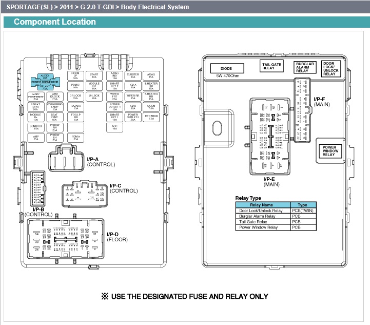
Solenoid safety interlock switch circuit diagrams of components with guard non contact magnetically coded toggle wiring diagram for idem switches 2018 catalogue by how to install sentrol guardswitch fortress interlocks amgard pro series 301 bt door monitoring a tgard architectures pt 1 what er relays and where china high quality key 4. 34 40A** PCM relay power (3.7L, 5.0L and 6.2L engines) 50A** PCM relay power (3.5L engine) 35 — Not used 36 30A** Roll stability control (RSC)/Anti-lock brake system (ABS) 37 - TT left stop/turn relay 38 — TT right stop/turn relay 39 - TT back-up lamps relay 40 — Electric fan relay 41 — Not used 42 5A* Run/start coil The diagram references LOCK and UNLOCK relays but in reality there are no physical electromagnetic relays as would be found in vehicles from several decades ago. I have corrected and applied a label which is more appropriate in meaning. The actual lock / unlock functiionality is activated by door lock drivers as referenced in the diagram. It is a standalone device that you can easily program with a video guide, detailed wiring diagram and a keypad. A waterproof structure on its metal control device is strong in adaptability and conforms to the IP68 degree. Because of the lock relay output, you can have a standard or secure mode, Wiegand 26 input/output, and NO / NC output.
The electronic door lock actuator is the part that latches and locks/ unlocks the door in a car with power locks. In most modern cars, the door lock actuator assembly includes a built-in latch mechanism, as well as the switch (sensor) that monitors if the door is open or closed/locked. FOLLOW: fox body , 79 93 mustang. All to often we at Late Model Restoration have noticed how hard it is to find a thorough Fox Body fuse panel diagram guide so we wanted to make this a little easier for enthusiasts like yourself. Check them out below and solve your pesky fuse issues today! Looking for wiring diagram for 2008 sierra Crew cab Dually for the rear door locks and relay location. Thanks 2008 GMC CC Dually Summit White D/A, Sunroof, DVD Player, Carpet Delete 8'6" Arctic Plow,20K Drawtite 5th Wheel Power Door Lock Wiring Diagram : Door Locks 5 Wire Alternating 12 Volts Positive Type C Relay Wiring Diagram : Provides circuit diagrams showing the circuit connections.
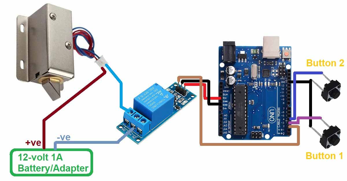
Interface a Solenoid Door Lock with Arduino - ElectroVigyan
In this video tutorial you are going to see the location and diagram (explanation) of VW Passat B6 (2005-2010) fuse panel (box). Below you can see the fuse colours: HERE You can find Car Fuses Assortment Kit, Standard & Mini Size: . You have to replace the defect fuse with a new fuse of the same ampere number!

Where exactly is the power door locks relay on a 91 Olds ...
Architectural wiring diagrams take effect the approximate locations and interconnections of receptacles lighting and unshakable electrical facilities in a building. Ignition interlock wiring diagram notice snubbing diode see reference info below internal to sequencing relay from pins 87 to 31 this ponent is intended to clamp the reverse voltage.

How-to-guides - Relay applications
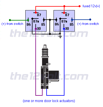
Door lock circuit 4 door. Wiring diagram quote form. The relay and wiring are shown in the diagram above. Single wire door lock systems type f type g type h there may be one two or three wires in the harness not counting the illumination wire s if any and only changes in voltage and or resistance on one wire to lock and unlock.

Door Locks Integration with Remote Start: I Just Installed a ...
The door lock relay module will interface with most electric power door lock systems drawing 30 ... WIRING DIAGRAM A: (+)12V pulses driving factory relays.3 pages
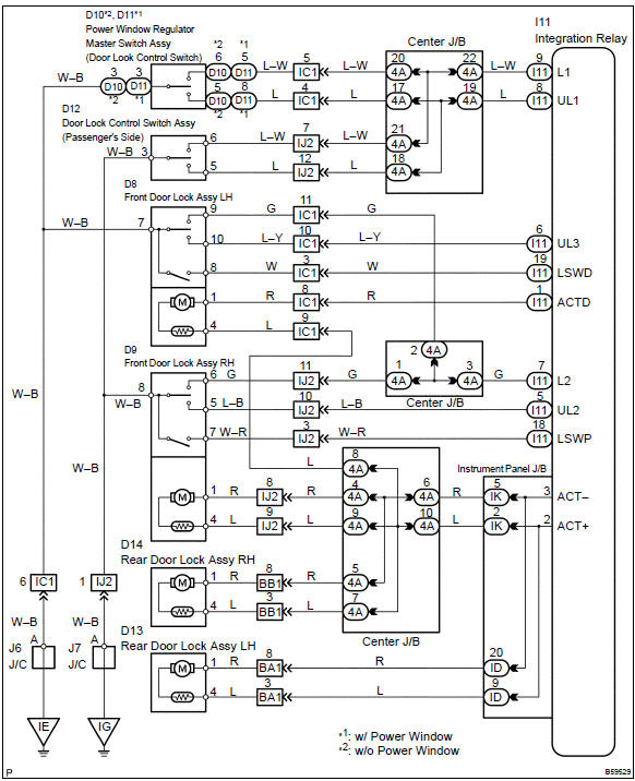
Toyota Corolla Repair Manual: Circuit description - All door ...
A wiring diagram usually gives opinion virtually the relative direction and bargain of. 2002 Chevrolet Silverado 1500 Owners Manual. Im looking for the drivers door lock. 1 RedRock 4×4 Off-Road Wiring Harness with Relay and Switch.

Central locking (power door locks) relay not working | Suzuki ...
The Password Based Door Lock System with the 8051 Microcontroller is a simple project that uses a secure password to unlock the door. Traditional lock systems that use a mechanical lock and key mechanism are being phased out in favor of more modern locking mechanisms.
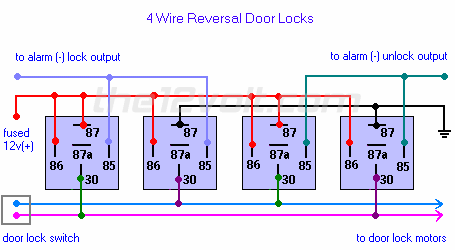
Door Locks - 4 Wire Reversal Relay Wiring Diagram
Karr 4040A Alarm System Wiring Diagram - i wanted to know if anyone has a wiring diagram for the Karr 4040A, also i know it has two different door lock harnesses. one is a 2 pin green and red, and a 4 pin harness. is either of these an input off the door locks to get the factory remotes to work?? i
How To Wire Up A 5 wire Relay For Positive Door Locks Actuators Invert Converter
Working of the project. Connect the 5 volts adapter to the circuit so that Arduino can start working. We are also sharing the code and circuit diagram for this project. There is a solenoidal lock connected with the relay module and controlled by the Arduino. If you want to open the door then enter the passcode and you can also see the values on ...
Power door Locks questions | GBodyForum - 1978-1988 General ...
The way to connect a NO lock to relay 1: - Connect the positive of the power supply to the common of the video door phone. - Connect from NO1 to the positive of the lock. - Connect the negative of the power supply directly to the negative of the lock. In case it is an NC lock, it is exactly the same, only NC1 will be used.
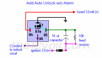
Multiple Wire Power Door Lock Systems, Add Auto Lock/Unlock
Arduino Relay Diagram. Here are a number of highest rated Arduino Relay Diagram pictures on internet. We identified it from trustworthy source. Its submitted by dealing out in the best field. We say yes this nice of Arduino Relay Diagram graphic could possibly be the most trending subject with we portion it in google help or facebook.
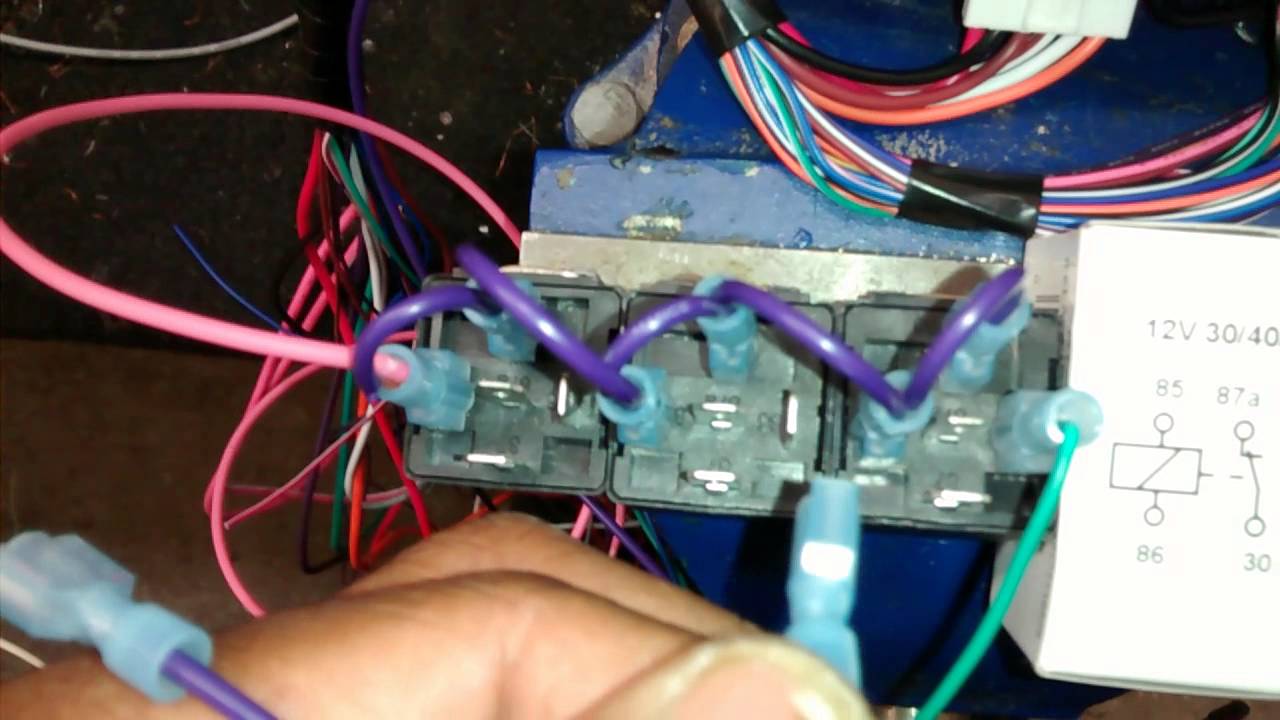
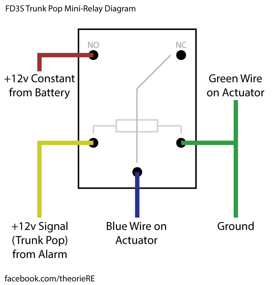
How to wire door lock relays for aftermarket actuators.
Relay module & solenoid lock or Servo motor x1; Connecting wires/jumper wires Circuit connections The door lock system consists of two critical circuits - the access control system and a locking mechanism. For the access control system here, an RFID is used. This door lock uses an RC522 RFID reader to read MIFARE and NTAG compatible RFID cards.
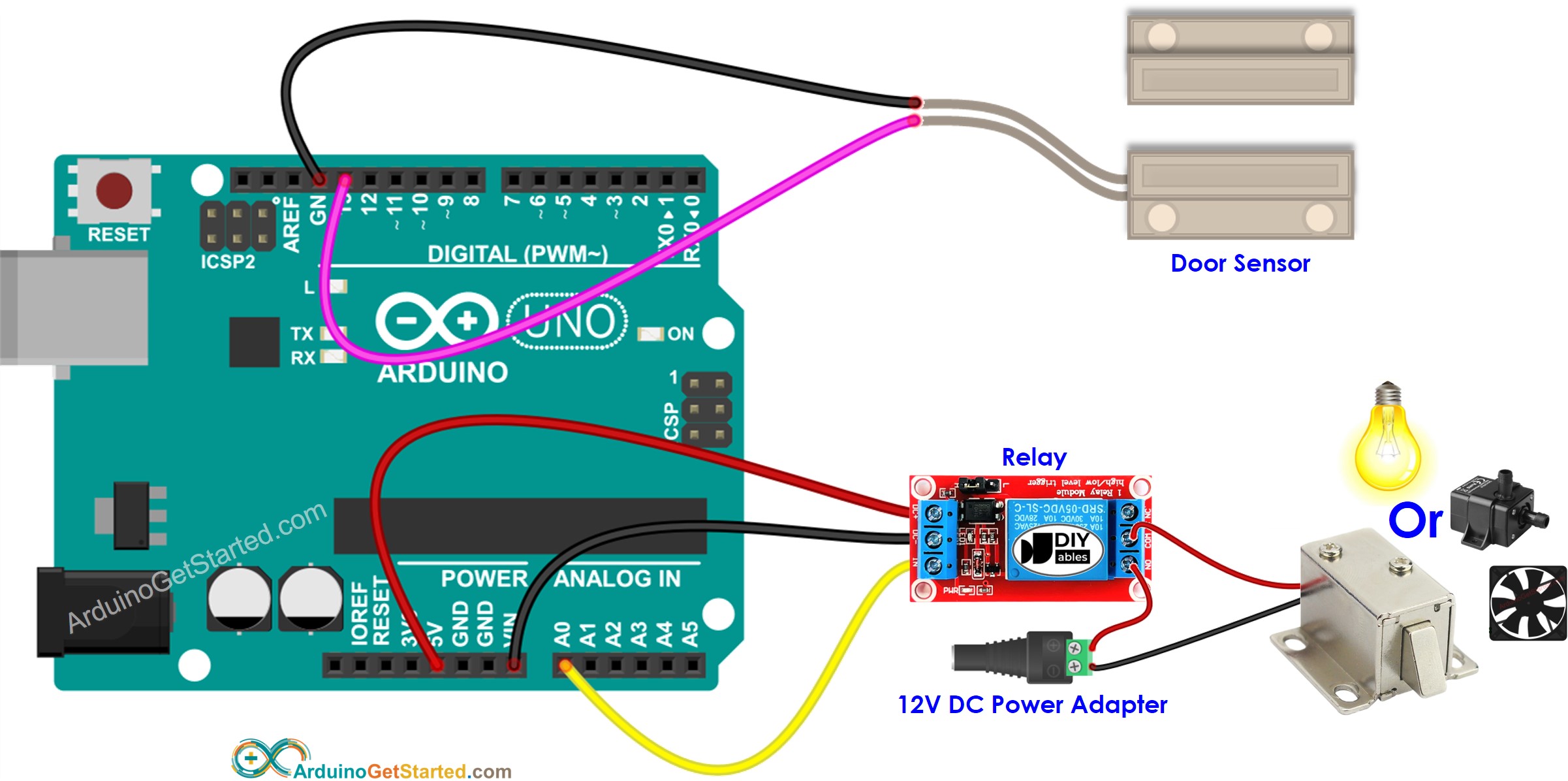
Arduino - Door Sensor - Relay | Arduino Tutorial
KASEKENNY1. EXPERT. There are a number of things that could cause this, but I would start with removing the relay and jumping pin 1 to 2 and see if the door opens. This will prove out the wiring and actuator. If it does then we need to check the fuse that feeds pin 3 shown in the diagram. Then we need to check to see if the BCM is grounding the ...

Wiring Diagram
Hyundai Sonata (2009 - 2010) - fuse box diagram. In this article you will find a description of fuses and relays Hyundai, with photos of block diagrams and their locations. Highlighted the cigarette lighter fuse (as the most popular thing people look for). Get tips on blown fuses, replacing a fuse, and more.

Lock Unlock Door For Home Automation :
Fuses and relays Toyota RAV4 (XA40), 2012 - 2019. 02.07.2021. Most electrical circuits in the vehicle are protected by fuses. Powerful current consumers are connected via relays. Fuses and relays are installed in mounting blocks located in the passenger compartment and in the engine compartment. The information is suitable for Toyota RAV4 (XA40 ...
CENTRAL DOOR LOCK(SET) 4PCS Car Central Motor Center Centre Moto Relay Wiring Kereta Wira Kancil Kelisa Saga Kenari
The negative terminal of the lock goes back to the Ground (0V) of the 12VDC power supply. Now when the RFID reader reads a RFID card, Rpi will checks if RFID card read is valid, and if yes, would trigger the Relay channel. Now COM will disconnect from NC. In other words, the 12VDC power to the lock is cut off.
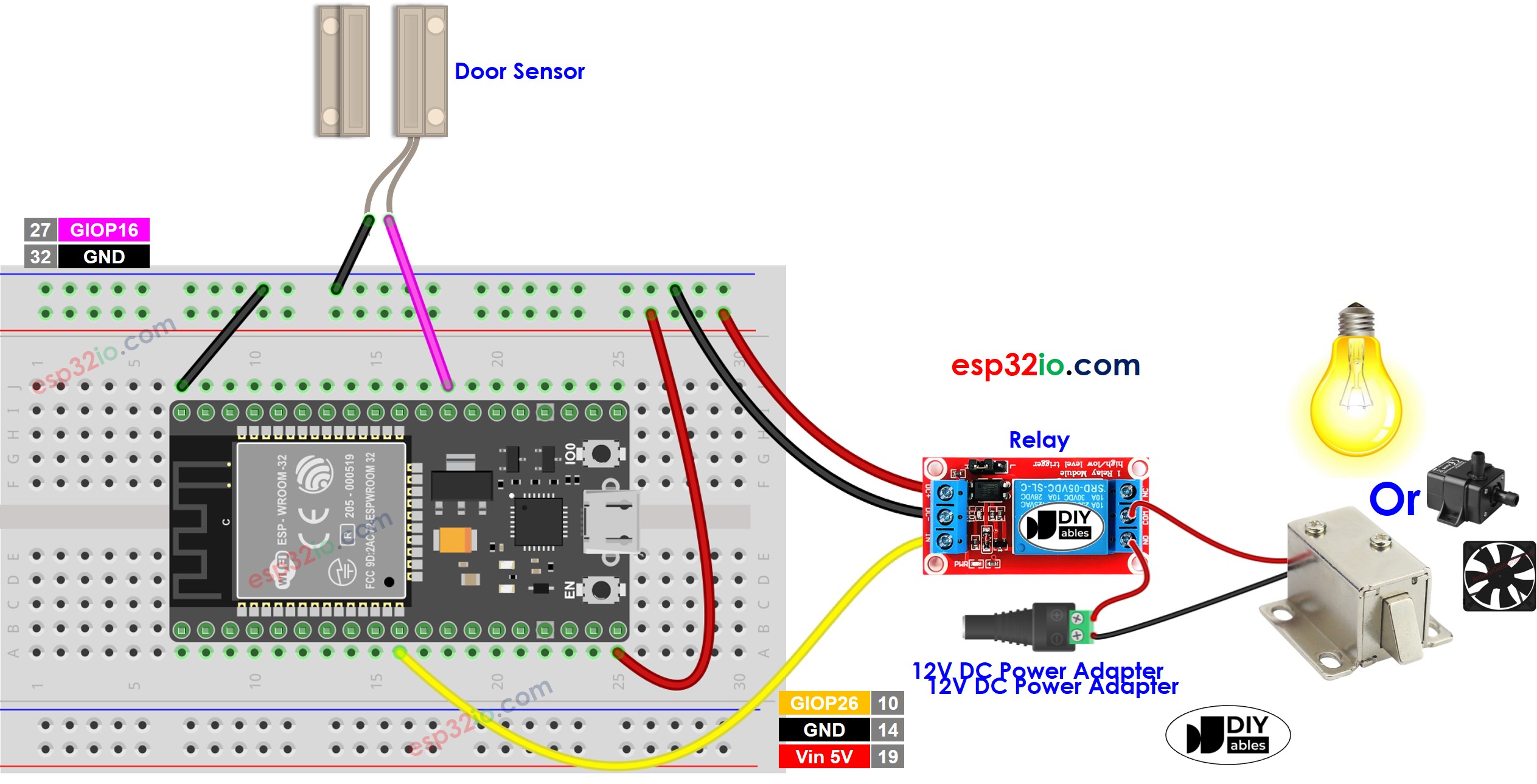
ESP32 - Door Sensor - Relay | ESP32 Tutorial
The door locks are control by relays. There is a fuse block on the LH side rear floor. (see diagram). There are few relays that controls the door lock on that vehicle. First do a visual inspection of the relays. You can also test the relays as well:

CAR POWER DOOR LOCKS - How To Troubleshoot PT. 1 of 2
Dodge Journey (2010) - fuse box diagram. Jonathan Yarden Oct 22, 2021 · 5 min. read. In this article you will find a description of fuses and relays Dodge, with photos of block diagrams and their locations. Highlighted the cigarette lighter fuse (as the most popular thing people look for). Get tips on blown fuses, replacing a fuse, and more.
wiring diagram for aftermarket door locks - Car Audio Forumz ...

door lock relay diagram Questions & Answers (with Pictures ...

door lock relay location | Suzuki Forums
Installing Actuators
Rear Latch and Door Lock Relay location??? | Kia Forum

5 Pin Relay Wiring Diagram | Electrical circuit diagram ...
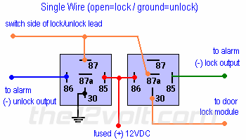
Single Wire Power Door Lock Systems, Type F, Type G, Type H
Power Door Lock Relay on 2002 Excursion - Ford Truck ...

Central Locking Relay Configuration Diagrams | Manualzz

Type C actuators
FD Alarm with Automatic Door Lock (FAQ) - RX7Club.com - Mazda ...
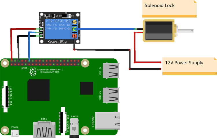
IoT Based Solenoid Door Lock using Raspberry Pi 4

Power Door Lock Install on a Jeep Wrangler YJ

I am installing 524T universal door lock actuators, as part ...

CENTRAL LOCK PENDIDIKAN TEKNIK OTOMOTIF: Media Pembelajaran ...

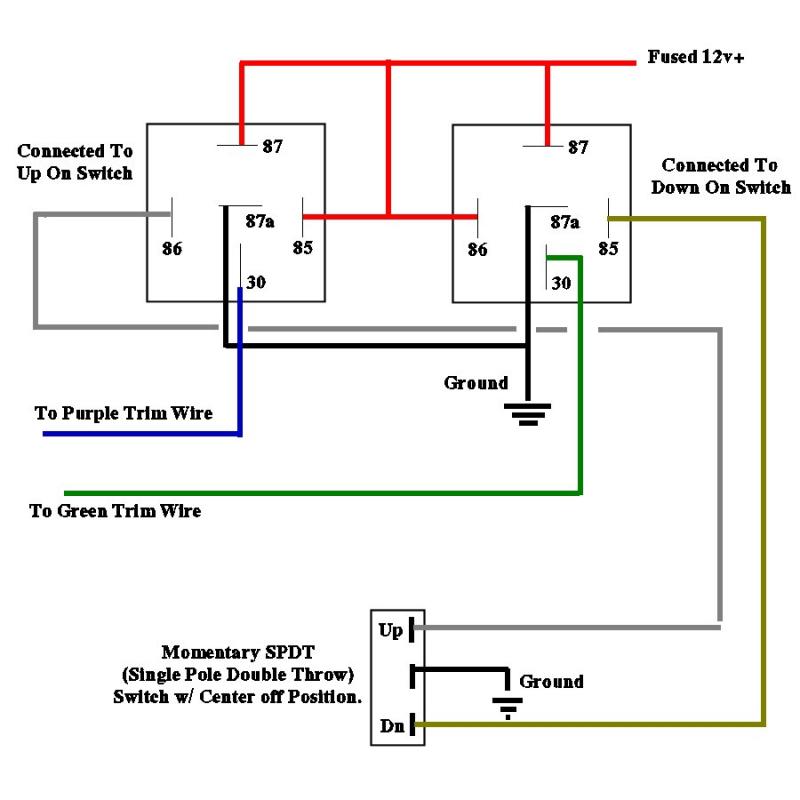
How to Wire Relays - Door Locks - Single Pulse to Lock and ...

POWER DOOR LOCK SYSTEM
Gatekeeper Instructions v4 h4.2
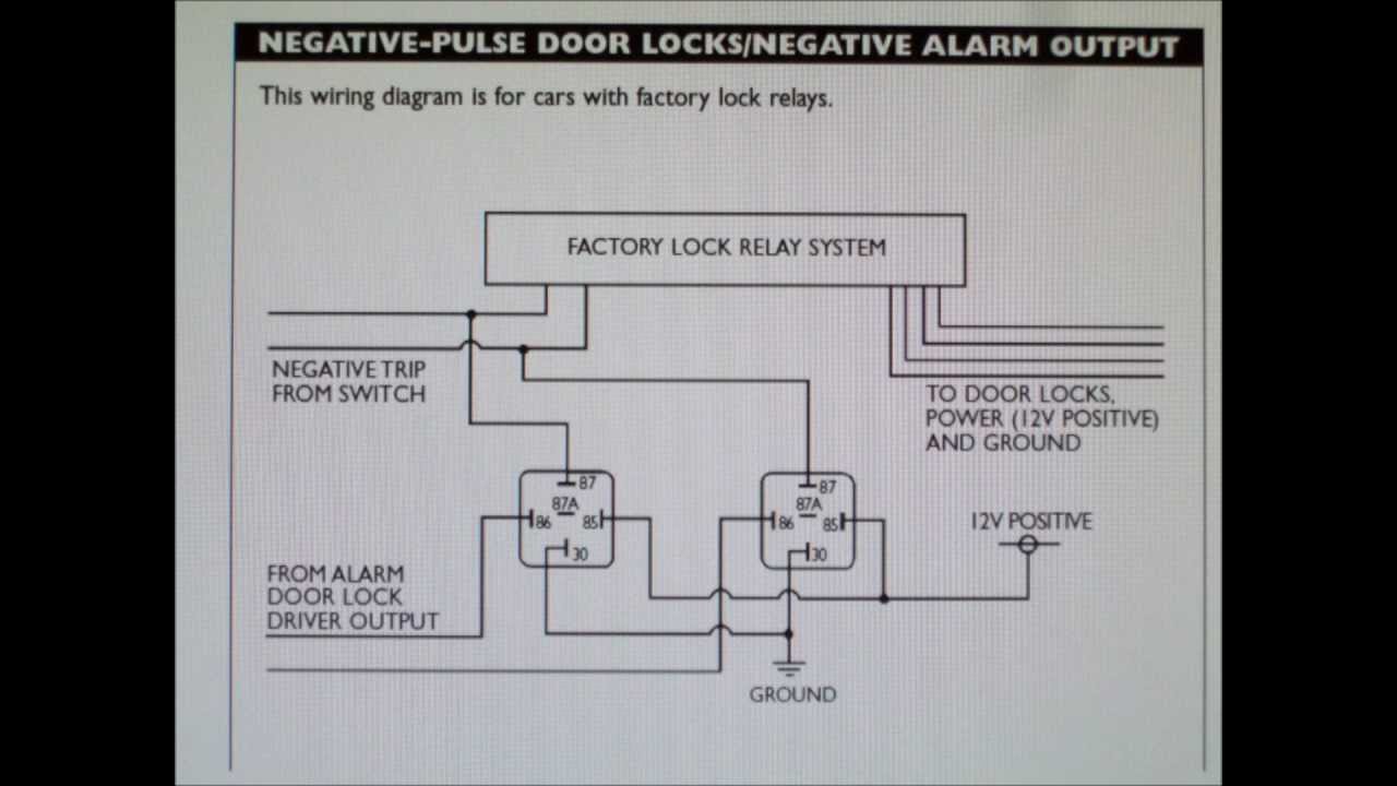
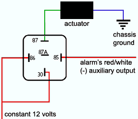
How To Wire Your Alarm To A Car With Negative Door Lock System
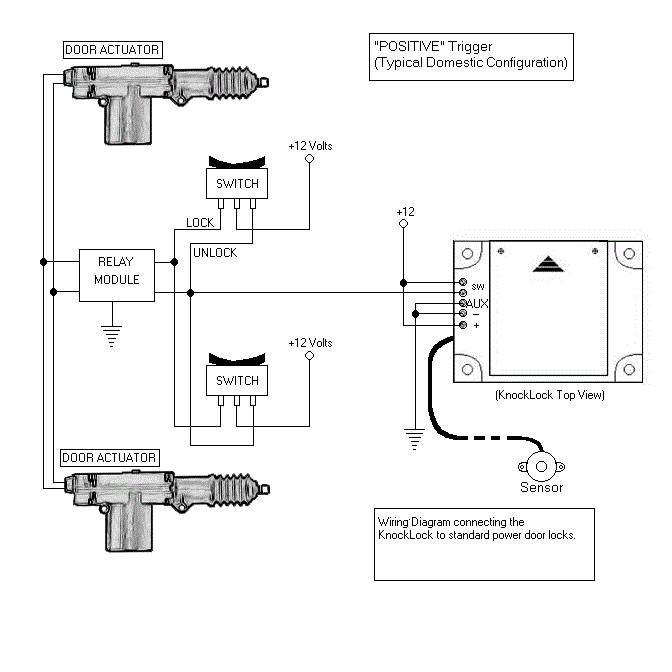
Knock lock (Knocklock) - Knock To Unlock
Door Locks - Actuators / Reverse Polarity - Positive Switch ...
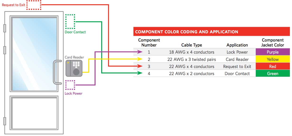
Access Control Cables and Wiring Diagram | Kisi

Car Alarm - Door Lock Wiring


Comments
Post a Comment