40 ge ballast wiring diagram
GE BallastBrochure11 08 648355 Catalog 1 | BALLASTS Instructions and wiring diagrams on each ballast label help assure a correct installation the first time. Total performance system™warranty. Since the mounting and. wiring footprints are the same as a standard ballast, our low profile HP models will easily retrofit into any. T12 or T8 fixture. SOLVED: How do I wire a ge ballast p.n.532-2995? - Fixya Expert. 270 Answers. Re: How do I wire a ge ballast... Your ballast kit replacement has a diagram in the box. Make sure you get the correct ballast kit. The diagram is pretty complicated, unless you know how to read prints. Posted on Dec 30, 2014.
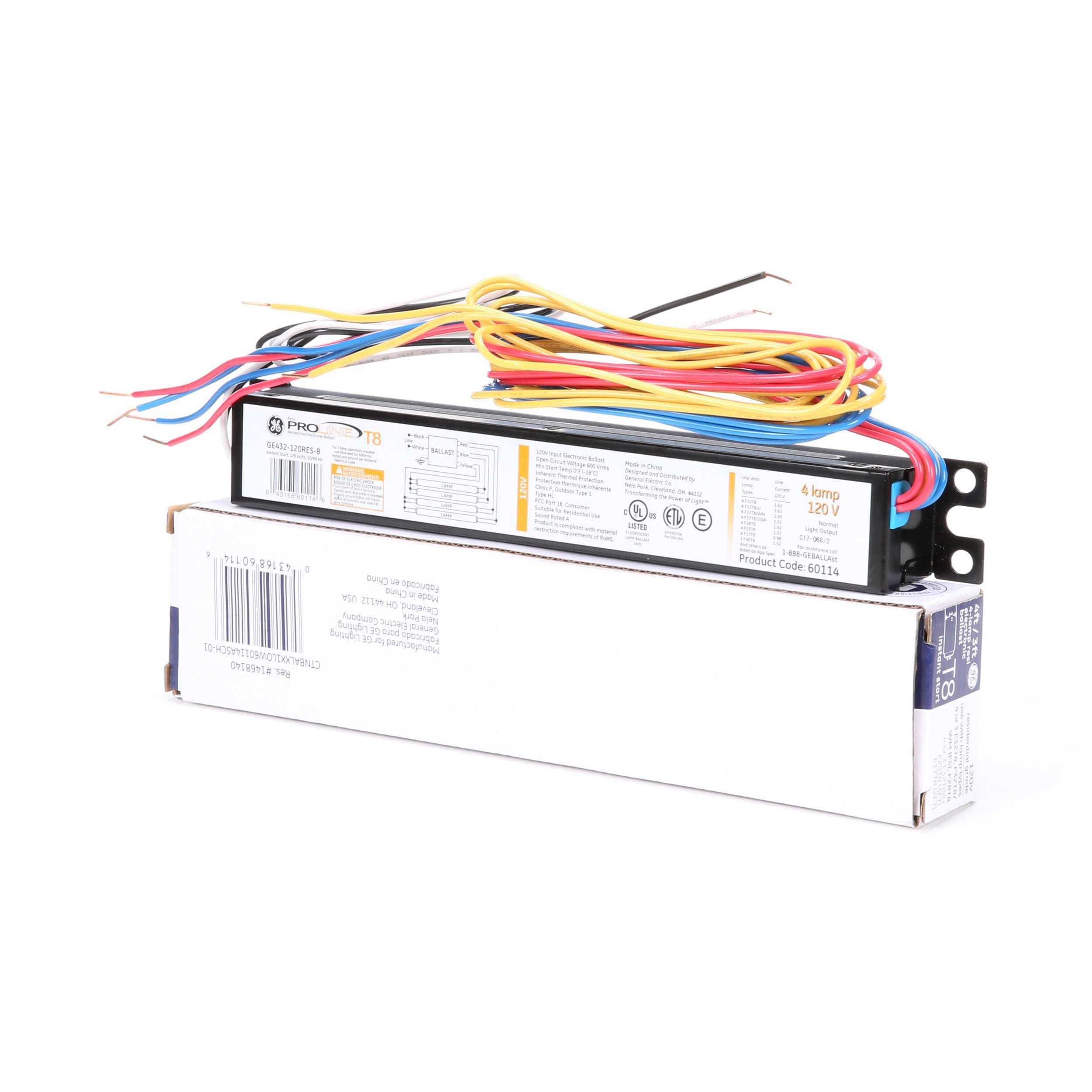
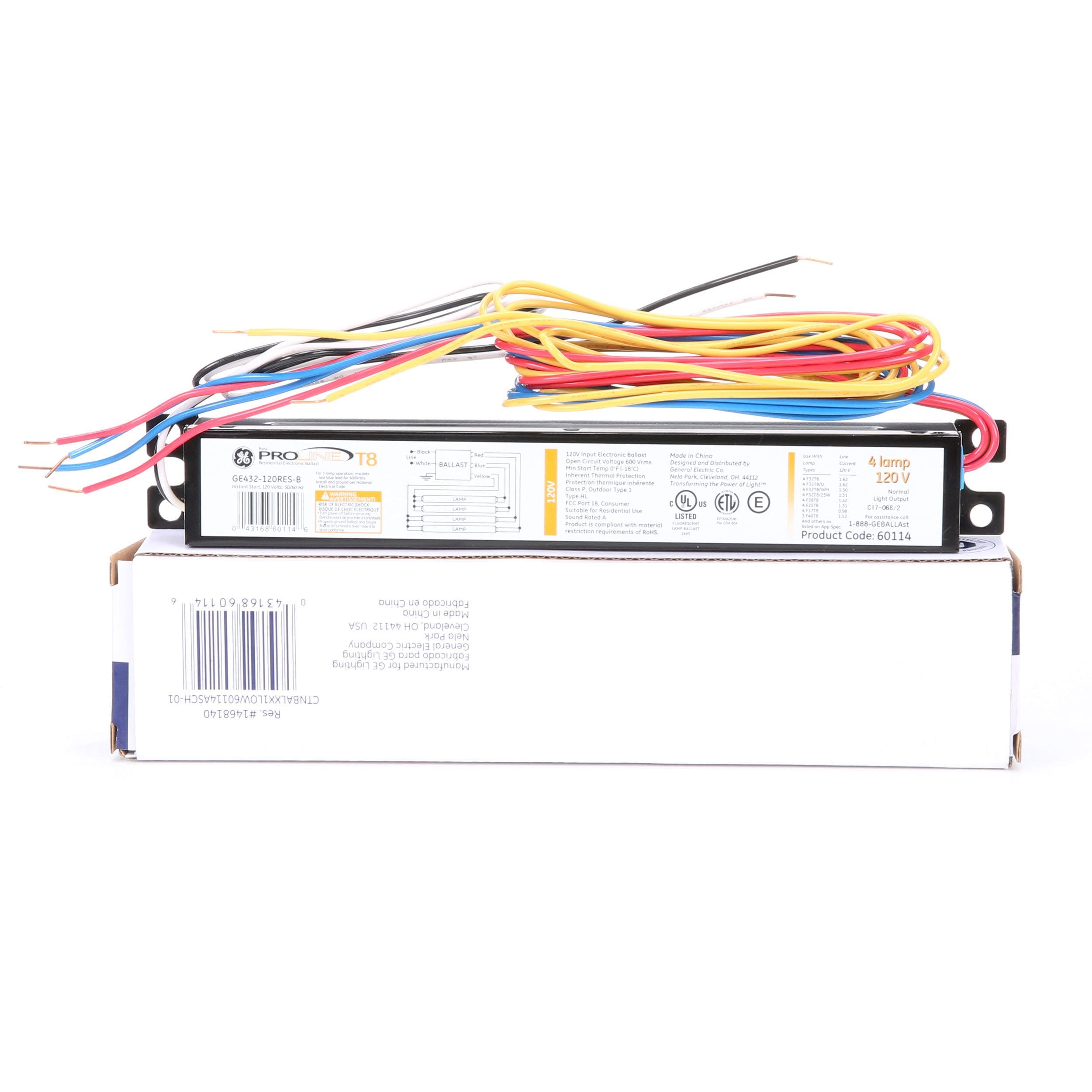
T8 Ballast Wiring - Help Needed - DoItYourself.com Community Forums My fixture has more wires than my new ballast (and even an extra color). 9 times out of ten there will be a great diagram printed right on the ballest. What do I do with the yellow wire? For reference, the new ballast is a GE Proline...

Ge ballast wiring diagram
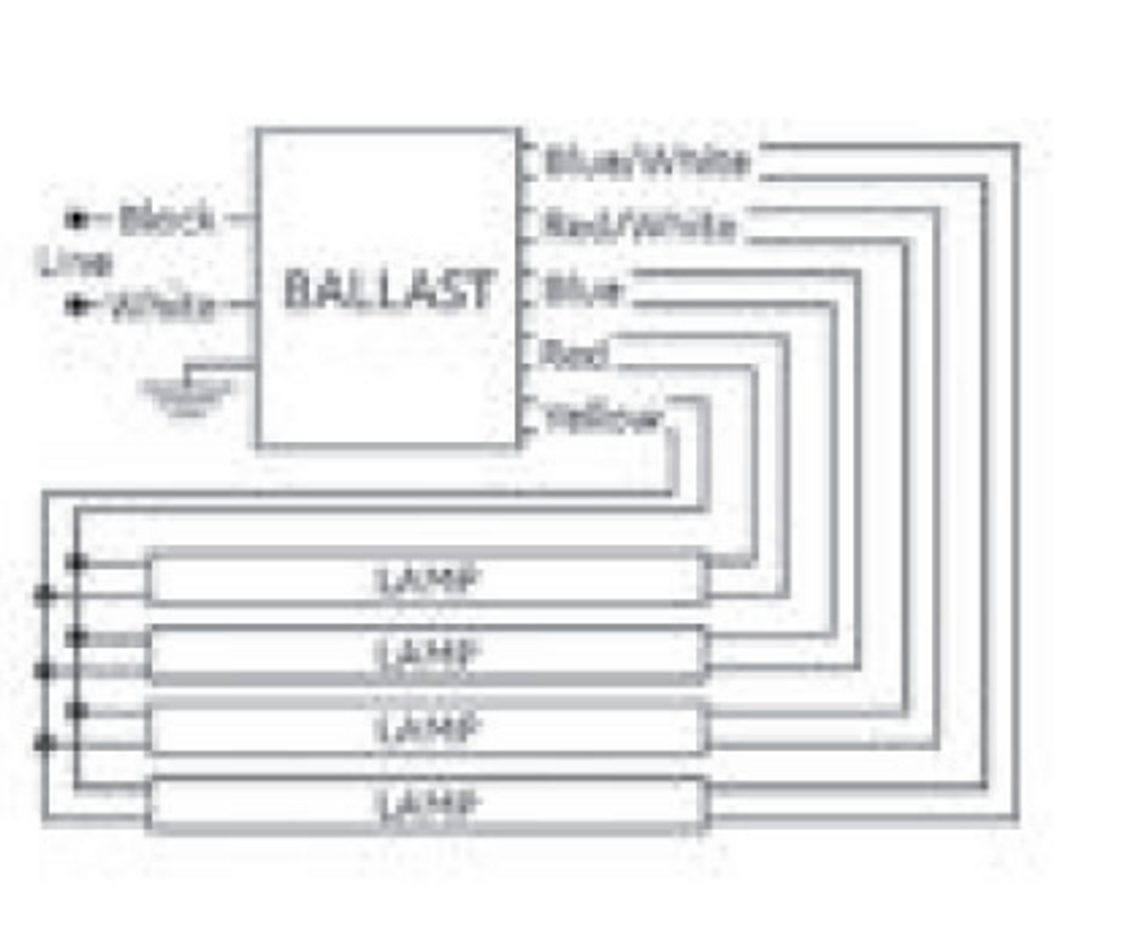
PDF ge ballast wiring diagram Assortment of ge t12 ballast wiring diagram. A wiring diagram is a streamlined standard photographic representation of an electric circuit. It reveals the parts of the circuit as streamlined forms, as well as the power and also signal links in between the devices. Ge T12 Ballast Wiring Diagram Gallery - Free Catalogs A to Z Collection of ge t12 ballast wiring diagram. A wiring diagram is a streamlined conventional pictorial representation of an electric circuit. It shows the elements of the circuit as simplified shapes, as well as the power and signal links between the gadgets. 400 Watt Hps Ballast Wiring Diagram - Wiring Schema Metal Halide Ballast Wiring Diagram Diagram Ballast High. Fluorowing Compact Fluorescent System Veseysseeds Veseys. Ge 120 To 277 Volt Electronic Ballast For Hi Output 8 Ft 2 Lamp.
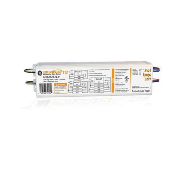
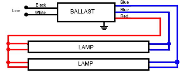
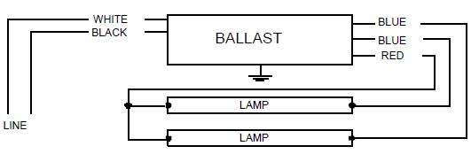
Ge ballast wiring diagram. GE UltraStart Proline Electronic Ballast, 120/277 Volt... - Amazon.com GE 74472 GE240RS-MV-N 120/277-volt Multi-Volt ProLine Electronic Fluorescent T12 Programmed Rapid Start Ballast, 2 or 1 F40 or F34T12 lamps. There is even a connection diagram printed on the ballast showing you where each wire should be connected. These ballasts are also light, weighing... Ge Wiring Diagram For Ballast Bypass Error Details: lamp Ge Ballast Wiring Diagram Diagrams T12 Ballast Wiring Volt ProLine Electronic Fluorescent T12 Programmed Rapid Start Ballast 2. Lamp Wiring. Parallel Wiring diagram - LFL 2 - see example on page . Ge Electronic Ballast Wiring Diagram - Car Wiring Diagram File Name : ge_ballast_wiring_diagram_ballast_wiring_diagrams_t12_residential_electrical_symbols_u2022_rh_bookmyad_co_4.jpg Dimensions : 600x526 Ratio : 8:7 File Size : 38 KB File Type : image/jpeg. 2 Lamp Ballast Wiring Diagram 2 Lamp Ballast Wiring Diagram. February 20, 2019. Series ballast lampholder wiring diagrams are shown with different numbers and combinations of lamps. . Electronic emergency ballast wiring diagram sign ballast wiring diagram ge electronic ballast wiring...
PDF LED Tube Ballast Compatibility | GE Lighting Product Code GE is a trademark of General Electric Company. Used under trademark license. HOWEVER - these tubes can also be used as a Type B lamp, where they can be used in a fixture that is re-wired to bypass the ballast. PDF GE Lamp & Ballast Products Catalog „ Section 18: Ballasts: HID... GE eHID ballasts improve the efficiency, maintain higher lumens, enhance lamp life and color control, and operate more quietly than the magnetic core Wiring diagram WD-eHID SLJ - see example on page 18-65 Case dimensions - Ref Drawing SLJ - see page 18-66 Length (L) Width (W) Height (H)... PDF Ge Ballast ELECTRONIC BALLAST. GE revolutionizes lighting again with new, breakthrough technology. In the GE labs, our engineers have developed a new voltages in excess of 300 Volts. It is imperative that proper connection to quality sockets be assured in accordance with wiring diagrams on each page of... I am replacing a GE Class P #8G1075 ballast with a new GE The old ballast has 2 red wires, 1 black, 1 blue and 1 white. And one white on the fixture coming from the end of the bulb to the white ground. May I have a picture of the wiring diagram that is on the new ballast? I have looked everywhere for some wiring references and cant find them, to be able to assist...
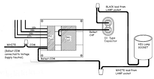
Electronic Ballast: Working Principle & Circuit Diagram | Electrical4U An HID ballast (HID stands for High-Intensity Discharge) is a device that is used to control the voltage and arc current of High-Intensity Discharge lamps during their operation. The circuit diagram for the various types of HID ballasts is shown below. High Pressure Sodium Ballast Wiring Diagram - Wiring Diagram... Ballast wiring diagrams for hid ballast kits including metal halide and high pressure sodium lighting ballasts. High pressure sodium ballas... 400 Watt Hps Ballast Wiring Diagram - Wiring Schema Metal Halide Ballast Wiring Diagram Diagram Ballast High. Fluorowing Compact Fluorescent System Veseysseeds Veseys. Ge 120 To 277 Volt Electronic Ballast For Hi Output 8 Ft 2 Lamp. Ge T12 Ballast Wiring Diagram Gallery - Free Catalogs A to Z Collection of ge t12 ballast wiring diagram. A wiring diagram is a streamlined conventional pictorial representation of an electric circuit. It shows the elements of the circuit as simplified shapes, as well as the power and signal links between the gadgets.
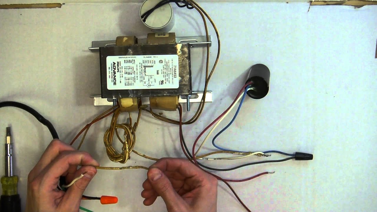
2. Philips self-oscillating electronic ballast. | Download ...
PDF ge ballast wiring diagram Assortment of ge t12 ballast wiring diagram. A wiring diagram is a streamlined standard photographic representation of an electric circuit. It reveals the parts of the circuit as streamlined forms, as well as the power and also signal links in between the devices.

Wiring 1000w HPS Core and Coil Ballast
mercury vapor ballast wiring diagram
GE 4-Bulb Residential Electronic Fluorescent Light Ballast in ...

Fluorescent Light: Ballast Replacement
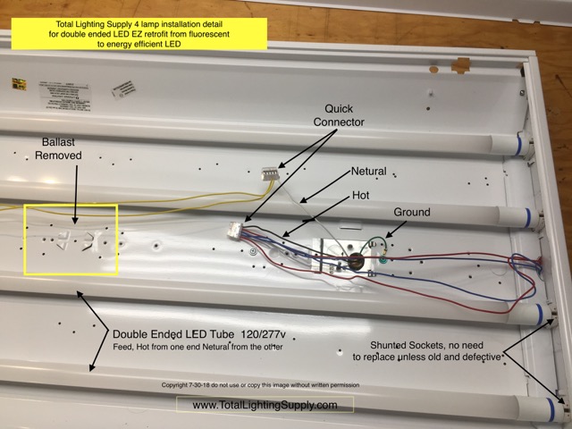
EZ LED T8 Installation Guide Video & Diagram

Peculiar problem with t12 ballasts... | DIY Home Improvement ...

GE 4-Bulb Residential Electronic Fluorescent Light Ballast

Customer Question Need wiring diagram for a GEM120PH120 ...

Led Puck Under Cabinet Lighting Direct Wire 2021 ...

Universal Lighting Technologies ULTim8® B232PUNVHE-B TRIAD® 2 ...

GE GE432-MVPSH-V03 Fluorescent Dimming Ballast, 4-Lamp, 32W ...

Universal Lighting Technologies ULTim8® B432IUNVEL-A TRIAD® 4 ...
GE GE332MAXPN/ULTRA | Turtle & Hughes

GE GE-432-120-PS-N ELECTRONIC FLUORESCENT BALLAST, 4-LAMP, T8 ...

What are the two yellow wires from a ballast for? - Quora
T8 LED Bulb Replacement Wiring Instructions, specs from www ...

GE WM7M Installation Guide | Manualzz
120-Volt Electronic Ballast for 3 ft. or 4 ft. 1-Lamp T12 or T10 Fixture
B232I120L GE/Magnetek/Triad Electronic Ballast [B232I120L ...
GE 4-Bulb Residential Electronic Fluorescent Light Ballast in ...

1.18 Ballast Factor F32T8 GE UltraStart 29675
light ballast wiring diagram Questions & Answers (with ...
GE CID1000/HR/G38 99-0422 Light Bulb, Replacement Lamp
Additional Ballast Wiring Diagrams - HPS ballasts

GE UltraSmart 3-Bulb Residential/Commercial Electronic Fluorescent Light Ballast

I am replacing a sun park SL15T ballast with a GE232-120RES-8 ...
Additional Ballast Wiring Diagrams - HPS ballasts
GE454MVPS90-F GE (67566) UltraStart Electronic Ballast

GE B432I277EL/ULTRA TRIAD ELECTRONIC BALLAST, 277V, F32T8, 4 ...

GE 2-Bulb Commercial Electronic Fluorescent Light Ballast in ...

Universal Accustart5 B228PUNV-C 2 Lamp F28T5, F21T5 or F14T5 ...

GE 74472 - GE-240-RS-MV-N T12 Fluorescent Ballast
Ballast

GE296HO-MV-N (75671) GE Multi-Volt ProLine Electronic Ballast

78811 General Electric - Distributors and Price Comparison ...

fluorescent ballast replacement - DoItYourself.com Community ...

GE 78625 - T8 Fluorescent Ballast

Florescent ballast repair wires don’t match (old) magnetic to (new) electronic. Color wire different

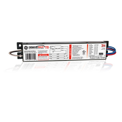
GE 78627 GE432MAX-N/ULTRA LFL UltraMax Electronic High ...


Comments
Post a Comment