43 irrigation wiring diagram
X2™ CONTROLLER WIRING DIAGRAM Water main Master valve (Optional) Water to zones Solenoid valves X2 controller Power (120 VAC transformer) Additional valves Irrigation wire (18 AWG) Common wire = Station wires = Use sheathed, direct-burial irrigation wire. Use waterproof connectors for all wire splices. hunter.direct/x2help Troubleshooting Rain Bird offers many types of sprinkler systems, and they don't all come with color-coded wires. In those that do, the wire colors reflect the station number the wire controls. In general, the ...
Wiring diagrams, sometimes called "main" or "construc-tion" diagrams, show the actual connection points for the wires to the components and terminals of the controller. They show the relative location of the components. They can be used as a guide when wiring the controller. Figure 1 is a typical wiring diagram for a three-phase mag-

Irrigation wiring diagram
sprinkler system wiring diagram - What is a Wiring Diagram? A wiring diagram is an easy visual representation with the physical connections and physical layout of your electrical system or circuit. It shows how the electrical wires are interconnected which enable it to also show where fixtures and components may be attached to the system. You may have noticed a trend, you will always require at least one extra wire. You will need one individual wire for each solenoid valve and one common wire to be shared by all the solenoid valves. 5 Core Irrigation Cable . To begin wiring at the controller, with the power off, pull back the outer sheathing exposing the individual wires. Strip ... NOTE: High Voltage Wiring (Outdoor Model only) 1. Route AC power cable and conduit through the ½" (13 mm) conduit opening on the left side bottom of the cabinet. 2. Connect one wire to each of the two wires inside the junction box. The ground wire should be connected to the green wire. Wire nuts are provided to make these connections.
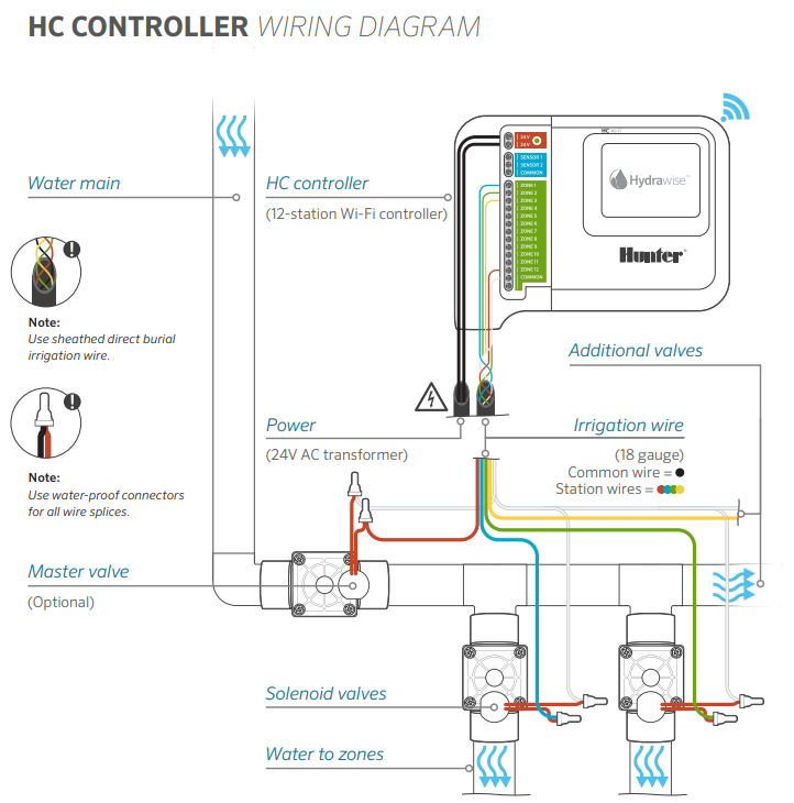
Irrigation wiring diagram. Wiring diagram for hunter sprinkler system. Hunter Sprinkler System Wiring Diagram Author. How to connect hunter x core master pro c connecting station wires hcc power module wiring diagram hc solenoid valves and ac controller guide irrigation plug pack src plus 2 by dlane wire rs terminal from x2 a valve rain bird sensor only one fault tracing ... HC CONTROLLER WIRING DIAGRAM Water main Master valve (Optional) Water to zones Solenoid valves HC controller (12-station Wi-Fi controller) Power (24V AC transformer) Additional valves Irrigation wire (18 gauge) Common wire = Station wires = Note: Use sheathed direct burial irrigation wire. Note: Use water-proof connectors for all wire splices ... Orbit Sprinkler Wiring Diagram - orbit sprinkler system wiring diagram, orbit sprinkler wiring diagram, orbit watermaster wiring diagram, Every electrical arrangement consists of various distinct parts. Each part ought to be placed and linked to different parts in particular way. If not, the arrangement won't work as it ought to be. Irrigation wire connectors, wet and damp locations 21 - 23 Wire Marking Tags 22 LANDSCAPE LIGHTING Low Voltage Lighting Cables 24 Timers 24 Photo Controls 24 Waterproof Connectors 25 Low Voltage Lighting Components 26 CONTACTS 27 WARRANTY 27 photo: courtesy Hunter Industries ...
Warning! Any pump start relay wired to an irrigation controller should have all unused station wires connected to the last used station wire. See Figure 7. The following diagrams show wiring details for pump start relay and pump motor starter wiring for various Rain Bird controllers. Figure 1: This is a basic pump start wiring diagram for most ... This article explains how to wire an irrigation valve to an irrigation controller. Rainbird Wiring Diagram Remotely manage irrigation systems from your computer or smartphone with Rain Bird's IQ Platform. Save time and water by managing multiple sites and. Automated Rain Bird irrigation systems are composed of three essential parts: Wiring the solenoid correctly ensures the correct valve is activated when turned. In the diagram below, you see a clear example of the wiring for a four-valve controller system. 1 - The "P" wire. The wire connecting to the master valve; 2 - The Master Valve. The master valve is an isolating valve that is an additional feature on certain controllers. A master valve will isolate your irrigation system and minimize water leaks.
This short video shows you the basics of wiring valve solenoids and sprinkler timersFind our preassembled manifolds here: ... Variable Rate Irrigation Prescription Software User Guide: PDF: 7.26 MB: Download: VFlex™ Corner Owner's Manual: PDF: 7.29 MB: Download: VFlex™ Corner Sequencing Control Panel Owner's Manual: PDF: 4.19 MB: Download: VRI-iS Pivot Prescription Software Version 8.55 User Guide: PDF: 3.68 MB: Download: VRI Linear Prescription Software User ... Orbit sprinkler wiring diagram. If it breaks the system won t work negating all the benefits of having it in the first place. The hydro rain b hyve pro wifi sprinkler controller lets you monitor and control your customer s use smart watering manual or a combination of both. The orbit b hyve is the best bud friendly smart sprinkler cnet. Sprinkler wire is a vital part of an underground system. If it breaks, the system won't work, negating all the benefits of having it in the first place. And because timers and valves are often separated by some distance, it can be a bit pain to repair. I asked some pro installers to share a few tips on how to easily install sprinkler wire and ...
Bits and Pieces
Mike Briley from Access Irrigation demonstrates how to wire a 24v irrigation solenoid valve into a mains powered irrigation watering controller using low vol...
How to Install an Irrigation Globe Valve
Having control over your irrigation, whether it's for commercial or residential use, is an important step for any gardener. We've put together a step-by-step guide showing you how to wire a K-Rain Solenoid Valve and Master Valve to our new WX8 Wi-Fi Irrigation Controller.. Watch our new "Three Minute Thursdays" video guide, or read through the steps below.

Field Wiring Diagram - Jain Irrigation Systems Ltd. - CADdetails
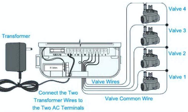
Terminal Strip Area - Use to attach transformer and valve wires from area shown in the diagram. 5.Below is a typical drawing and description of a Hunter SRC series timer Master/Pump valve wiring. Most sprinkler timers will be similar to this example.
Sprinkler system - long wires or long pipes? - Electrical ...
01.12.2018 01.12.2018 3 Comments on Hunter Sprinkler System Wiring Diagram Refer to the diagram below when connecting your solenoid valves to the controller. Water main Take one wire from each solenoid, twist together and connect to the common (usually white) wire of your multicore irrigation cable.

help wiring irrigation controler/rain sensor please : r ...
Orbit Sprinkler Wiring Diagram | Wiring Diagram - Orbit Sprinkler Wiring Diagram Furthermore, Wiring Diagram provides you with enough time body in which the projects are to be finished. You may be in a position to know precisely when the assignments needs to be accomplished, which makes it much easier to suit your needs to properly handle ...

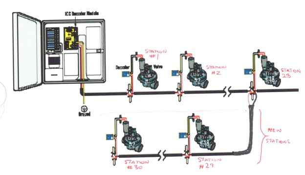
Underhill TW-ICC-48 Icc Decoder Module for Irrigation ...
The Paige Irrigation Wiring Guide for Decoder Systems Background: The decoder system was first introduced to the irrigation industry in the late 1960s. It was invented by the world renowned golf course architect, the late Robert Trent Jones, Sr. The first system was installed in Mr. Jones' personal golf course, Coral Ridge Country Club, in Ft.

22 Farm irrigation ideas | irrigation, sprinkler, sprinkler ...
The pump is a Myers HJ100S and the power is supplied by a 20A/250V three-prong plug with white, red, black, and bare copper wires. Here is an image showing the setup. On my pump the connector on the left is labeled L1 and the one on the right is labeled L2. I know where the grounding wire connects, but I'm not used to working with 240V.
Grounding & Troubleshooting Two-wire Systems
Complete this wiring only if you have a master valve installed in your irrigation system. A master valve is a "normally closed" valve installed at the supply point of the main line. The Generation 2 Rachio Smart Sprinkler Controller is designed to accommodate two sensors, a master valve or pump relay, and up to 16 zones.

Wiring 101: Zones, Commons, Master, Pump, Rain Sensor, 24VAC ...
A wiring diagram is a streamlined standard pictorial representation of an electrical circuit. Collection of sprinkler system wiring diagram. Water flow is measured in gallons per minute. Wiring a sprinkler system controller is fairly straightforward and involves matching your system s wires to the correct terminals.

3 Way Gel Connecter Cable Joiner
Most standard digital controllers, including Spruce, run off of 110/120 volts AC. For indoor use, these controllers can be plugged straight into a common house electrical outlet in the United States, Canada, and any other region that uses 110V for mains electricity. The AC transformer steps-down the power from 110 to 24 […]
Auto Irrigation System using Soil Moisture Sensor and PIC ...
Orbit 6-Station Easy-Dial Sprinkler Timer-57876 - The Home Depot - Orbit Sprinkler Wiring Diagram. Wiring Diagram consists of many in depth illustrations that display the connection of assorted items. It contains instructions and diagrams for various types of wiring techniques along with other items like lights, windows, and so on.
HC - Connecting Solenoid Valves and AC Power – Hydrawise
NOTE: High Voltage Wiring (Outdoor Model only) 1. Route AC power cable and conduit through the ½" (13 mm) conduit opening on the left side bottom of the cabinet. 2. Connect one wire to each of the two wires inside the junction box. The ground wire should be connected to the green wire. Wire nuts are provided to make these connections.

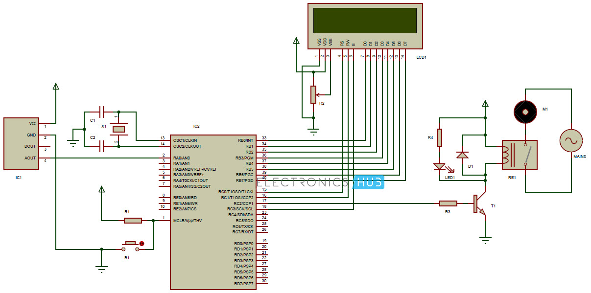
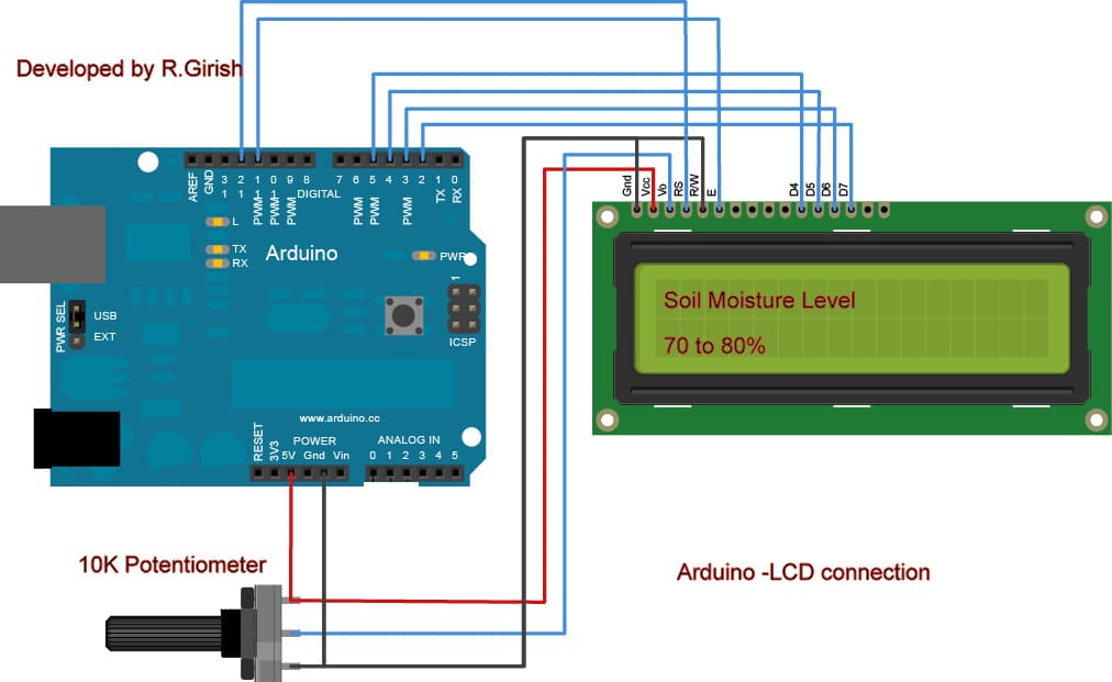
Smart Irrigation System - Circuit Diagram and Code
You may have noticed a trend, you will always require at least one extra wire. You will need one individual wire for each solenoid valve and one common wire to be shared by all the solenoid valves. 5 Core Irrigation Cable . To begin wiring at the controller, with the power off, pull back the outer sheathing exposing the individual wires. Strip ...
2 Wire Irrigation Decoders – TWL Irrigation
sprinkler system wiring diagram - What is a Wiring Diagram? A wiring diagram is an easy visual representation with the physical connections and physical layout of your electrical system or circuit. It shows how the electrical wires are interconnected which enable it to also show where fixtures and components may be attached to the system.

X2 - Connecting a Master Valve | Hunter Industries
The Paige Irrigation Wiring Guide for Decoder Systems
4,552 Automatic Sprinkler Stock Photos, Pictures & Royalty ...
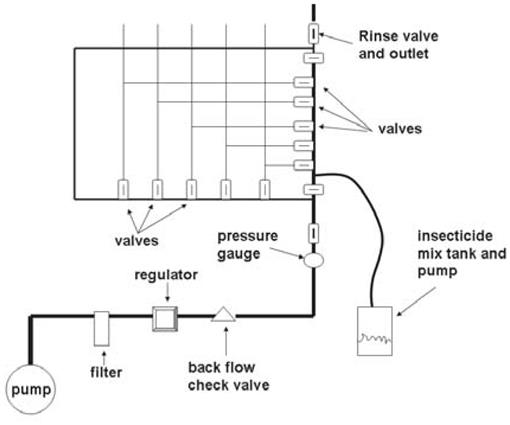
A Manifold for Injecting Insecticides into a Drip Irrigation ...

Automatic Irrigation System (Arduino) With Usb Type DC ...

Latest Posts | Rainmaker LLC | Lawn irrigation system repairs ...
Smart Irrigation Controller - Arduino Project Hub

Wireless irrigation control Patent Grant Tennyson , et al ...
.png?auto=compress%2Cformat&w=1280&h=960&fit=max)
Thingspeak and Internet Sprinkler - Hackster.io
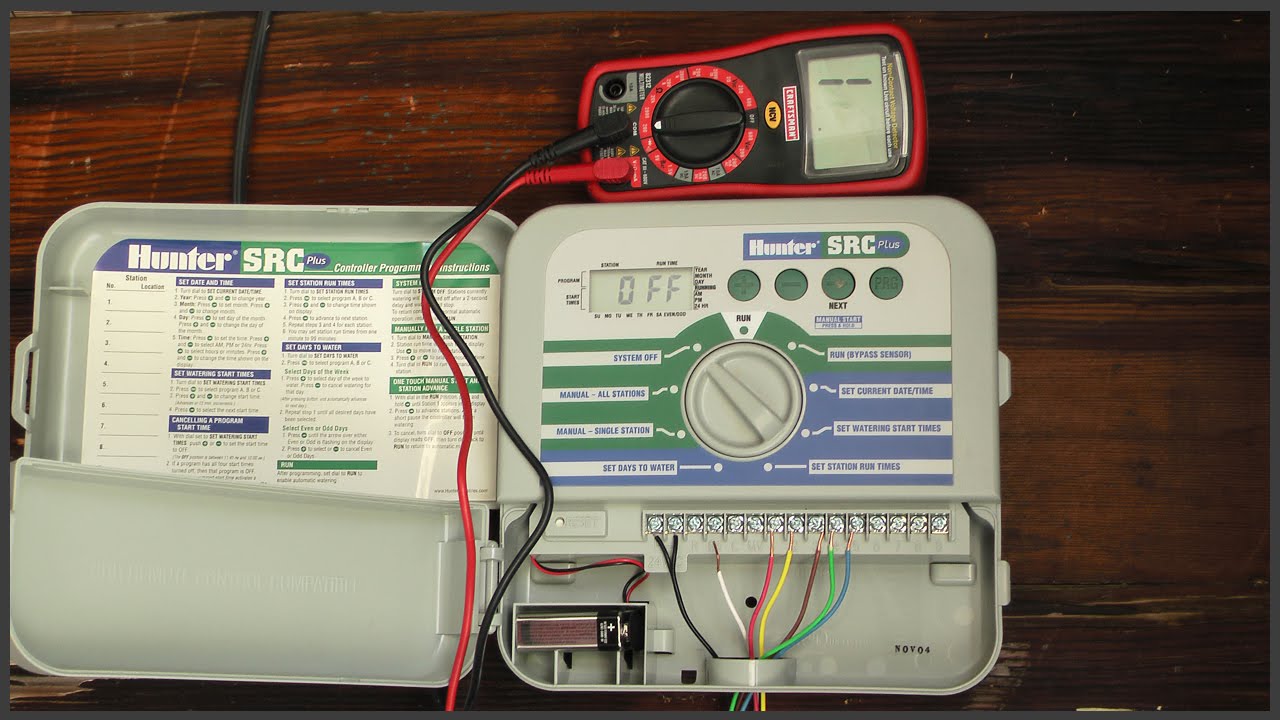
Testing Sprinkler System Wiring

How To Wire A Electric Actuator Valve? | COVNA Actuator
Mini-Clik II Instructions

Cat Starter Relay Wiring Diagram Auto Wiring Diagrams ...
Automatic Irrigation Circuit using Arduino - Homemade Circuit ...

Irrigation scheduling Water content Soil Wiring diagram, Soil ...

DOUBLER - 2 Valves on One Wire / Expand or Repair Your ...

How To Wire Up An Irrigation Controller | Waterpro Pty. Ltd.

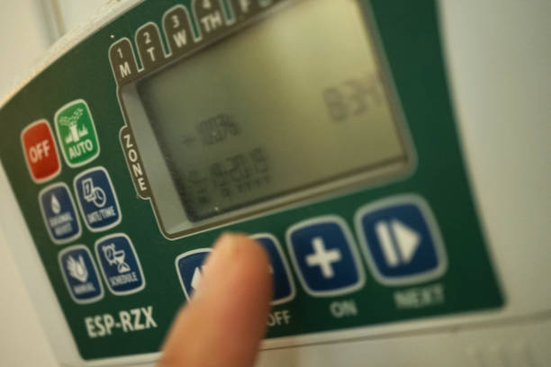
How to Replace a Lawn Sprinkler Timer: 12 Steps (with Pictures)

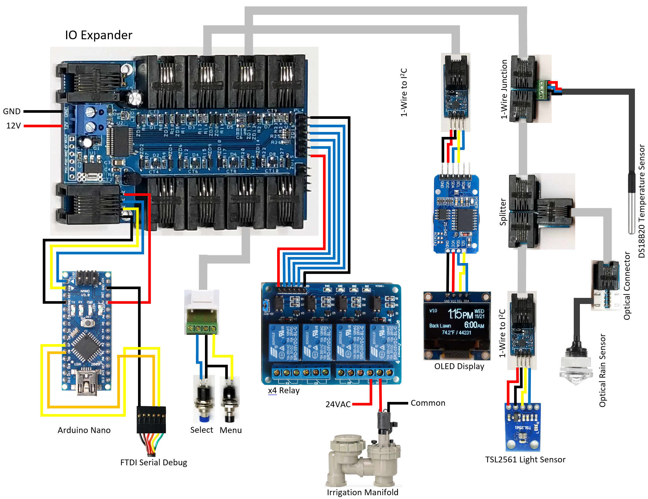
Irrigation Project Wiring : r/homeautomation
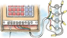
Installing & Wiring Sprinkler Valves - HomeTips
704 WEM Manual
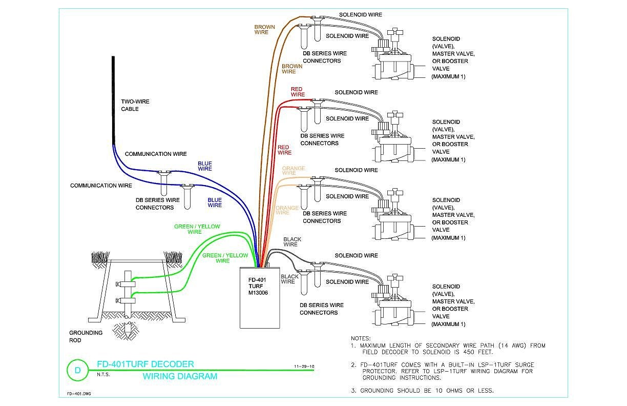
FD-401TURF Decoder Wiring Diagram | Rain Bird
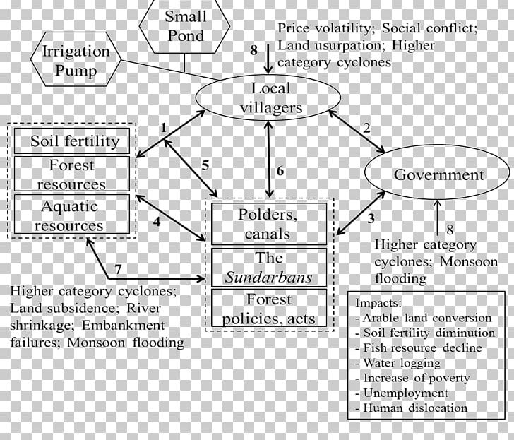
Wiring Diagram Robustness Ecosystem PNG, Clipart, Angle, Area ...

Help With 3 White Common Wires 2x Controllers - Wiring ...

Expand landscape irrigation with hybrid plan, Novo converter ...

Appendix B – Zimmatic Branded Pivots Wiring Diagram | Manualzz
Troubleshooting electrical issues in irrigation systems ...
Garden Monitoring Project
Uniformity testing of variable-rate center pivot irrigation ...


Comments
Post a Comment