43 on off timer circuit diagram
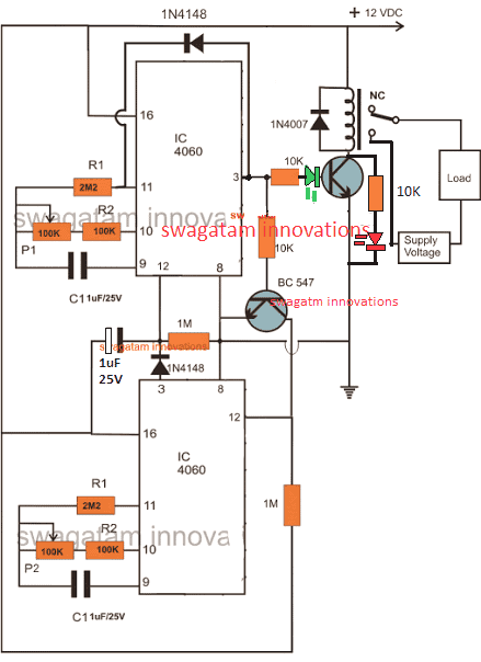
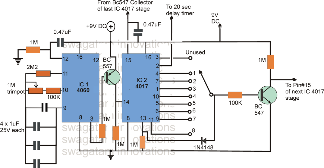
In this article, we are going to learn how to make an Automatic ON-OFF Buzzer Using 555 Timer. A buzzer is a high-frequency oscillator circuit use for generating a buzzing sound through a speaker or a transducer. In an Automatic ON-OFF Buzzer, we use a speaker due to which this buzzer is louder as compared to other circuits. Jan 20, 2021 · The ON time delay and the OFF time delay are independently settable and this facility becomes the most important feature of a programmable timer circuit. Using Versatile IC 4060. In this page we will discuss a very simple yet reasonably useful timer circuit diagram whose ON time and OFF time settings are independently adjustable through ...
On Delay Timer and off Delay Timer: Generally, timers are used to control the circuit for a certain amount of time. Using timers we can delay the circuit operation. Three types of timers are the most commonly used in the electric circuit. One is On-delay timer, the second one is off relay timer and the third one is star delta timer.
On off timer circuit diagram
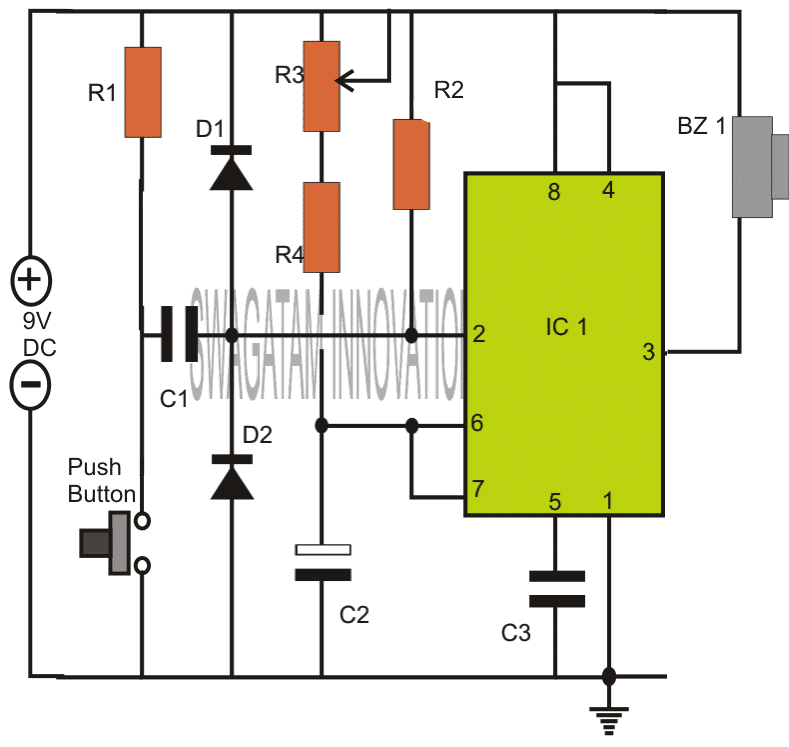
The Touch ON and OFF Switch Circuit is built around a 555 timer by making use of the default properties of the Pins of the 555 Timer IC. With the help of this circuit, you can turn ON and OFF a device by simply touching the Touch Plates. Ts18 Timer Wiring Diagram. Digital On Off Timer Switch Circuit Project Water Board सर क ट ब र ड P K Enterprises Jaipur Id 15710080891. Intermatic et1125c 24 hour 30 amp electronic time switch 120 277 vac nema 1. Fan timer switch wiring diagram. Need help wiring an intermatic. 555 Timer Delay Off Circuit Diagram. The above circuit uses a 555 timer U1 in mono stable mode. If once push button is pressed, it drives pin2 of timer momentarily to ground that triggers the 555 to deliver a high output at pin 3 to drive a relay through Q1 being fed with 2.2K resistor. The contact of the relay finally drives any external AC load.
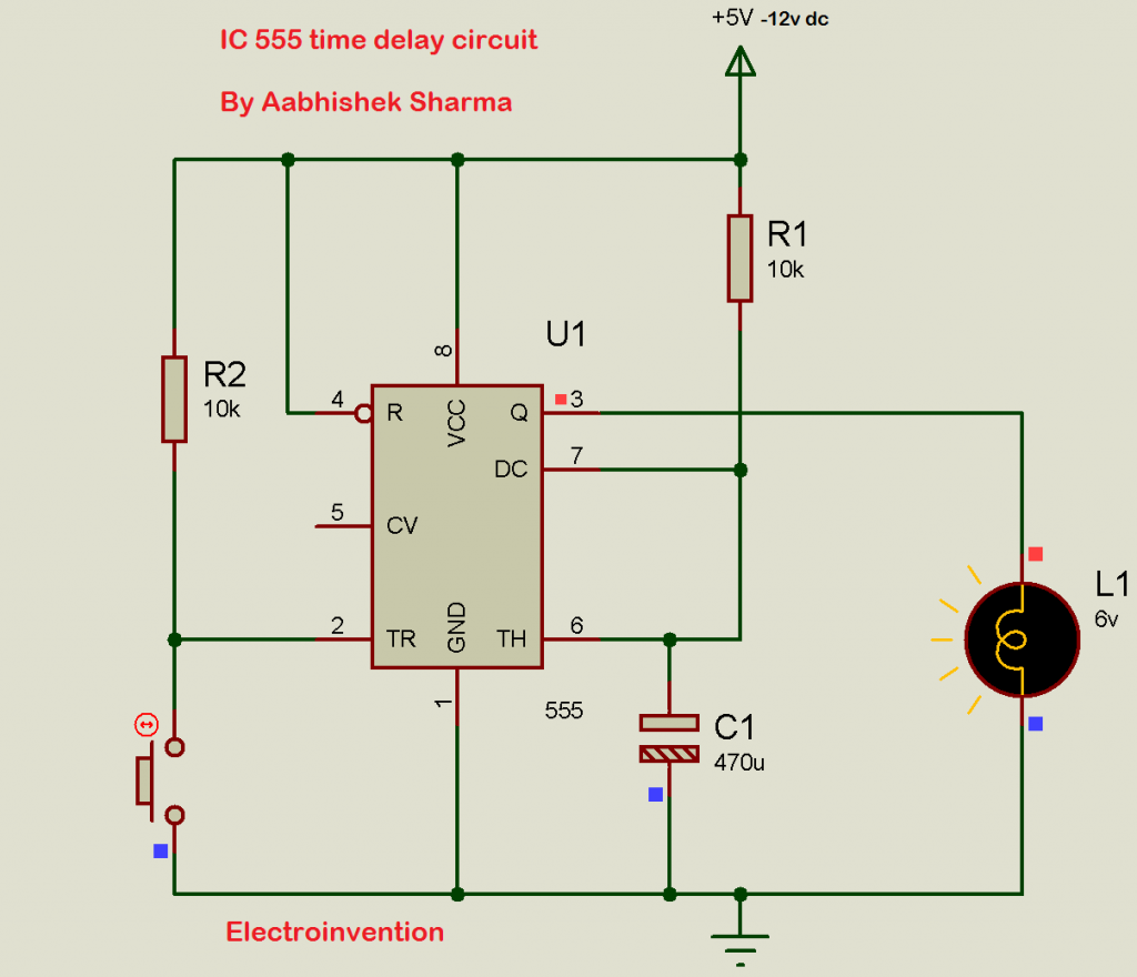
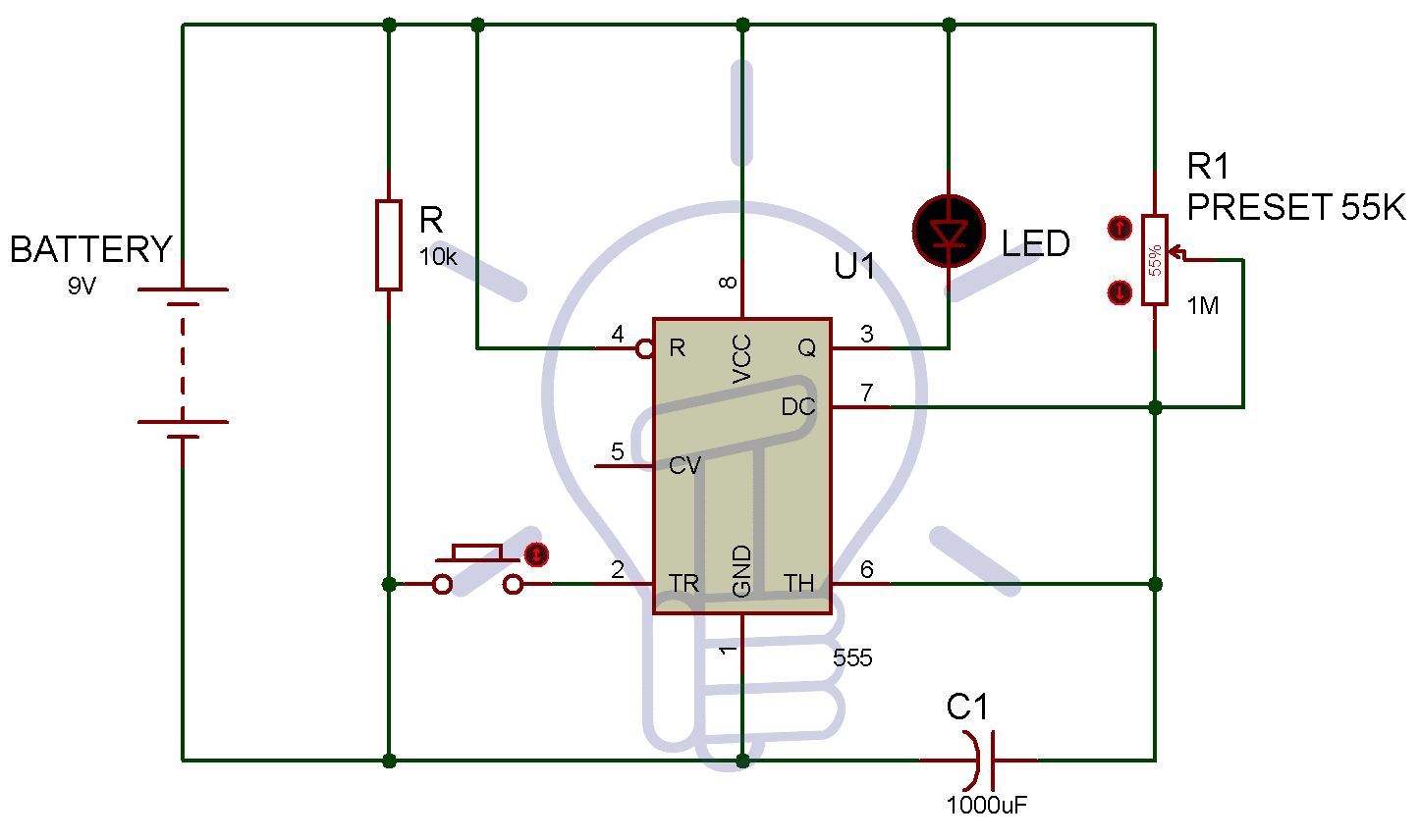
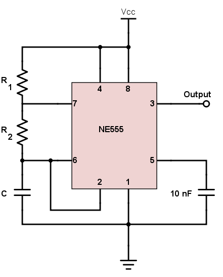
On off timer circuit diagram. Before going into detail of Time Delay Circuit, first we need to learn about 555 Timer IC first.Below you can find the pin diagram of 555 timer IC along with the details of each pin. Pin 1. Ground: This pin should be connected to ground. Pin 2. TRIGGER: Trigger pin is dragged from the negative input of comparator two.The comparator two output is connected to SET pin of flip-flop. Simple Delay Timer Circuits Explained. In this post we discuss the making of simple delay timers using very ordinary components like transistors, capacitors and diodes. All these circuits will produce delay ON or delay OFF time intervals at the output for a predetermined period, from a few seconds to many minutes. 0.3 Second to 10 Hours Timer Relay with 4541 IC. P. Marian. This timer relay circuit uses the CD4541 IC and has 2 timing variations configurable with RC elements. The specifications of this timer are: modes of operation: astable/monostable. the output has a 6A/250V relay with NC/NO contacts. Adjustable Delay On Off Timer Circuit. For adjusting the timer duration on the fly, the timing resistor is replaced by the potentiometer and its connections are made as shown in the circuit diagram below. You can choose the potentiometer value depending on the maximum duration you require. How This Circuit Works
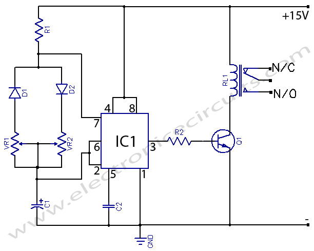
On delay timer circuit diagram wiring diagram contactor with push button circuit diagram of delay timer on off power off delay timer circuit diagram 2 way lighting circuit triggering transformer push button fan switch light activated switch circuit diagram wd081 text. Each component should be placed and linked to other parts in particular manner. Mar 24, 2019 · On/Off Timer Schematic Circuit Diagram. If you need an adjustable ‘on’ or ‘off’ time for some application, then this is the circuit you have been looking for. A problem that often occurs when adjusting timers are that the individual times affect each other. This circuit completely solves this problem because the time defining elements ... to the off state and remain in the off state until the set time elapses. The timer cycles between the two states until power is removed from the coil. Removing the coil voltage resets the timer. The set time for both the off state and the on state is the same. Applicable models: GT3A-1, -2, -3 and RTE-P(B)1. T T T Power Output Type No. GT3A-1 ... You can link any appliance to the relay and get it on and off continuously as the circuit can continue on and off the 12 volts relay. The circuit has a well-known NE555 timer IC which, due to its uses in the wide range of electronic circuits, is very popular. In the circuit, IC is connected as an astable multivibrator and the 12-volt relay is ...
555 Timer With On Off Delay Circuit Here is a timer circuit using common IC 555. The circuit is designed to facilitate time adjustment of both charged and discharged states of the relay.…Read more › 555 Timer Delay Off Circuit Diagram Eeweb Community. Timer circuit diagram with relay. 555 timer delay off circuit diagram eeweb community. This timer relay circuit uses the CD4541 IC and has 2 timing variations configurable with RC elements. The wiper of the variable resistor is connected to the positive terminal of a 1000µF capacitor. May 01, 2019 · The above circuit diagram is for the 1-minute timer circuit. For 5 min, 10 min and 15 min you just have to change the resistor value (R 1). 1 Minute Timer Circuit: We have to configure 555 Timer in Mono-Stable mode to build a timer. The 555 Timer starts timing when switched ON. After one minute of time duration, the LED will automatically turn ON. A tutorial on how to make a Touch On and Touch Off sensor switch using 555 timer IC on a breadboard. This circuit uses two pairs of touch conductors to sense and register the touch. One pair of touch conductors (sensors) for turning ON the output and the other pair for turning OFF the output. You can use any output device like DC motors or AC ...
How to make a simple circuit with a 12v relay that switches ...
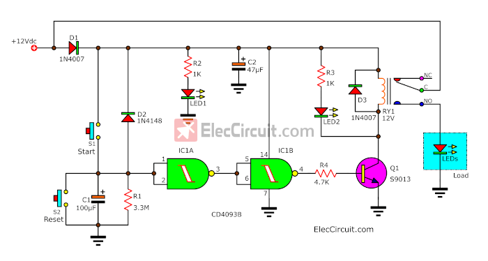
11.4 Use button to create self latching timer with ability to turn off..... 25 11.5 Delay Off timer with 0 power consumption in Off state ... Timer wiring diagram 2.1 Connecting 5amp timer
IC 555 Delay Timer circuit | Easy timer circuit | on off ...
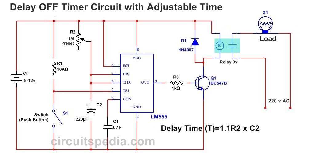
Switch ON Delay Timer Circuit Diagram Power ON Delay Timer If You Want to switch on any Load After Some Moment Or Some Duration Then You Can Use this Timer Circuit. This is Tested. Timing Can be Adjusted By Adjustment of Preset. This circuit is very useful in the Protection of Any Load.

Sequence Control: Off-Delay – Basic Motor Control
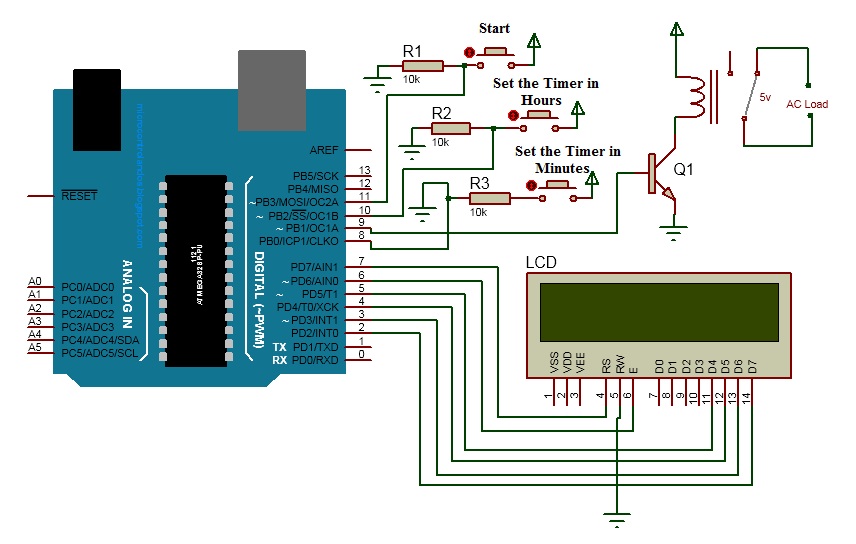
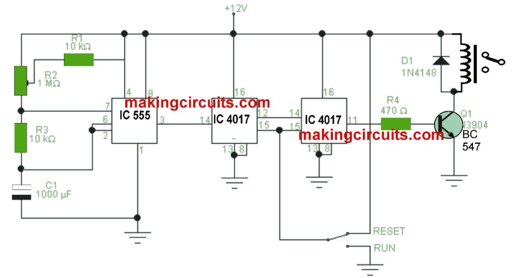
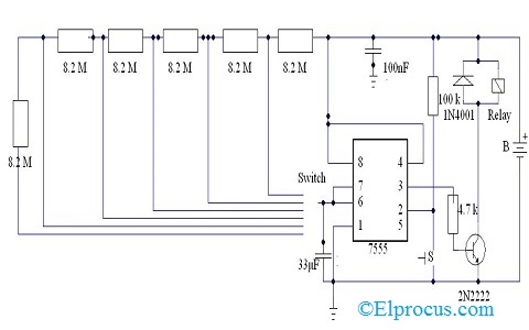
The above circuit diagram is for the 1-minute timer circuit. This Touch Switch Circuit Diagram is built around a 555 timer by making use of the default properties of the Pins of the 555 Timer IC. This will give an output at Pin 2 after about 9 Hours. Wiring diagram for timer and contactorSterilmatic fails to operate at all.
TOUCH SWITCH and TOUCH ON-OFF Circuit
The Touch ON and OFF Switch Circuit is built around a 555 timer by making use of the default properties of the Pins of the 555 Timer IC. With the help of this circuit, you can turn ON and OFF a device by simply touching the Touch Plates. If the touch plates are placed at a convenient location, we do not require to move from our place to turn on ...
DRIVING A RELAY Circuit
On Off Timer Circuit Diagram Level Beginner Description Power (a hot and a neutral) is fed to the switch with 1 switch leg run from the switch to 1 light. The parts values in these circuits were selected for testing purposes and can be adjusted to suit the needs of a particular application as long as the normal.
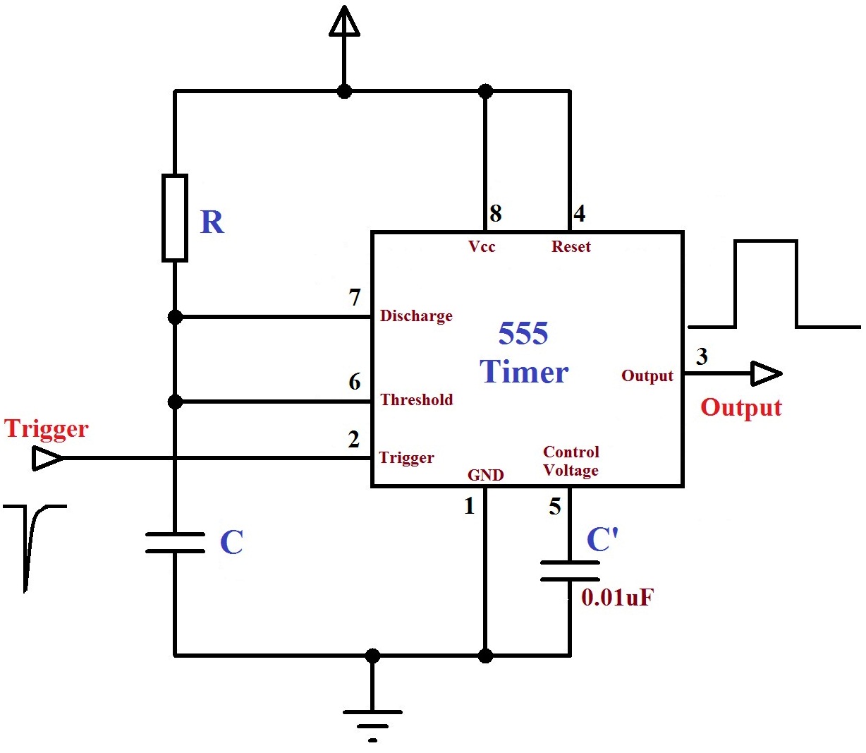
Monstable Multivibrator using 555 Timer
Delay OFF Timer circuit For OFF time Delay , Switch OFF Delay Timer Timer Circuit For Automatic Switch OFF Any appliance After a fix Time Duration. When switch S1 is pressed then Output Will Give HIGH signal at pin 3 and Transistor is ON , Therefore the connected load with relay is also switched on. … Delay OFF Timer Circuit Read More »
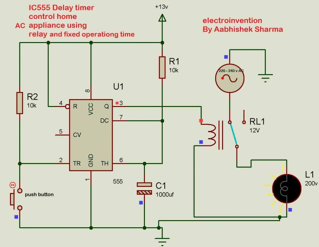
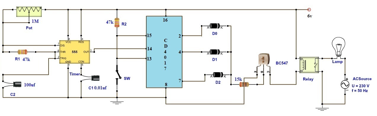
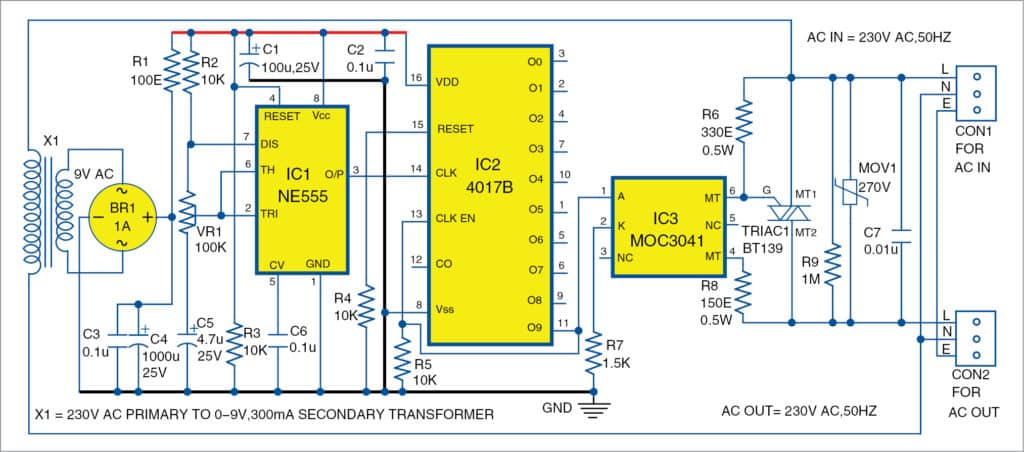
IC555 delay timer for controlling the on-off time of AC devices
What is a 555 delay timer? A delay timer is a circuit in which the component that you want to operate starts working after a time delay from the power is turned on. In this project, we have made both on and off delay timers and the individual circuit diagrams are also given below.

555 Timer Monostable Calculator
This ON-OFF Switch circuit uses the well known 555 timer. The timer activates a relay through a bipolar transistor in order to connect or disconnect the device we want to control. Manual activation is performed through two momentary contact switches. Switch 1 (SW1) is used to enable and Switch 2 (SW2) is used to disable the device.

555 circuits using the 555 Timer as an Astable Oscillator
A Push On Push off latching switch can use to ON and OFF the load alternatively with the same push action. Push on push off switch using 4017. This circuit is using a decade counter IC 4017, which counts or shifts the output for each rising edge of applied clock signal.The IC has 10 outputs, here only two outputs are used to switch ON and OFF by shifting the HIGH state between these two outputs.

ON-OFF Switch circuit using a 555 timer. This circuit is ...
Nov 9, 2018 - ON-OFF Switch circuit using a 555 timer. This circuit is usefull on places where we want to activate and deactivate an electrical or electronic device.
The circuit diagram of the auto power-off timer circuit ...
Below are few examples of timer circuits used in different applications. 1. Long Duration Timer. This timer circuit is designed to switch on a 12 V load in a solar-powered installation for a preset period at the press of a button. When the period has expired a latching relay disconnects both the load and the controller circuit from the 12 V supply.
Adjustable Timer Circuit Diagram with Relay Output
555 Timer Delay Off Circuit Diagram. The above circuit uses a 555 timer U1 in mono stable mode. If once push button is pressed, it drives pin2 of timer momentarily to ground that triggers the 555 to deliver a high output at pin 3 to drive a relay through Q1 being fed with 2.2K resistor. The contact of the relay finally drives any external AC load.

On/Off Timer - DIY Electronics Projects, Circuits Diagrams ...
Ts18 Timer Wiring Diagram. Digital On Off Timer Switch Circuit Project Water Board सर क ट ब र ड P K Enterprises Jaipur Id 15710080891. Intermatic et1125c 24 hour 30 amp electronic time switch 120 277 vac nema 1. Fan timer switch wiring diagram. Need help wiring an intermatic.
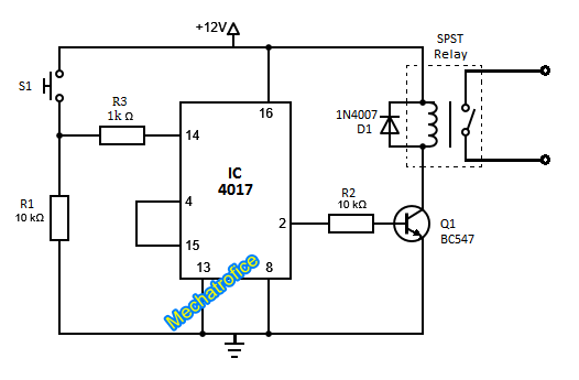
ON OFF Latching switch circuit diagram using IC 4017,555
The Touch ON and OFF Switch Circuit is built around a 555 timer by making use of the default properties of the Pins of the 555 Timer IC. With the help of this circuit, you can turn ON and OFF a device by simply touching the Touch Plates.

555 Timer Delay Off Circuit Diagram

Pin on Électronique
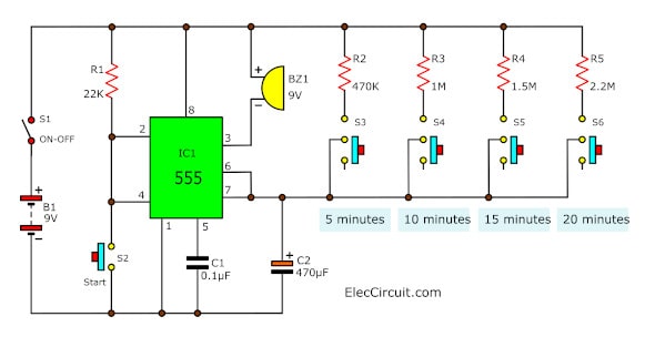
5-20 minuts timer circuit using IC 555 - ElecCircuit.com
Wide Range Timer circuit diagram and instructions

555 Oscillator Tutorial - The Astable Multivibrator
1 to 15 Minute Timer Circuit Diagram, Working and Applications

555 Timer Delay off Circuit with Circuit Diagram | 555 timer projects
Adjustable Timer Circuit Diagram with Relay Output
555 Timer Circuit With Variable On/Off Times Circuit Diagram
Simple Timer Circuits using IC 555 - Adjustable from 1 to 10 ...
Power-On Delay Timer Circuit | Full DIY Electronics Project
Simple Programmable Timer Circuit - Homemade Circuit Projects
1 Hour to 5 Hour Customizable Timer Circuit
555 Delay OFF Timer Circuit For Delay Before Turn OFF Circuit

Super Circuit Diagram: Timer Circuit with Independent On and ...
5 minute time delay circuit using CD4093 - ElecCircuit.com
Programmable Plant Watering Timer Circuit

1 Minute to 10 Minutes Adjustable Timer Circuit
555 Timer Astable Circuit - Electrical Engineering ...

555 Timer Tutorial - How To Configure a 555 Timer IC
how to build a 555 timer circuit for 5 seconds
30 Minute Timer Circuit Using 555 IC and 7555 IC

Automatic Turn OFF Power Circuit

1 Minute, 5 Minute, 10 Minute and 15 Minute Timer Circuit ...

555 Timer Astable Circuit Calculator
Timer With On-Off Delay | Electronic Circuits

Circuit Diagram - Easy project : 22 Clap ON/OFF switch ...
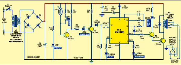
Automatic Off Timer For CD Players | Detailed Circuit Diagram ...

Time Delay Relay using 555 Timer, Proteus Simulation and PCB ...


Comments
Post a Comment