39 concrete column interaction diagram
Cantilever Beam | SkyCiv Engineering Mar 29, 2021 · Reinforced Concrete Tutorials. What is Reinforced Concrete? Column Buckling; What is a Column Interaction Diagram/Curve? Calculate the Moment Capacity of an RC Beam; Reinforced Concrete vs Prestressed Concrete; Connection Design Tutorials. Shear Connection; Moment Connection; Foundation Design Tutorials. Types of Foundation and their Uses; What ... Reinforced Concrete Column Calculation Eurocode 2 RC Column - M-N interaction diagram (EC2) Checked By Date CN 16.04.2014 Input  Output Column dimensions Moment capacity Reinforcement Materials (steel, concrete, bolts) RC Column - Axial Force - Bending Moment Interaction per EN 1992-1-1:2004*
Concrete Interaction Diagrams - Structural engineering ... RE: Concrete Interaction Diagrams IDS (Civil/Environmental) 4 Nov 10 18:51 The spreadsheet attached will do an interaction diagram for a rectangular section with or without prestress and with a rectangular stress block or a parabolic-rectangular stress block (as well as elastic analysis, crack widths, time related strains etc).

Concrete column interaction diagram
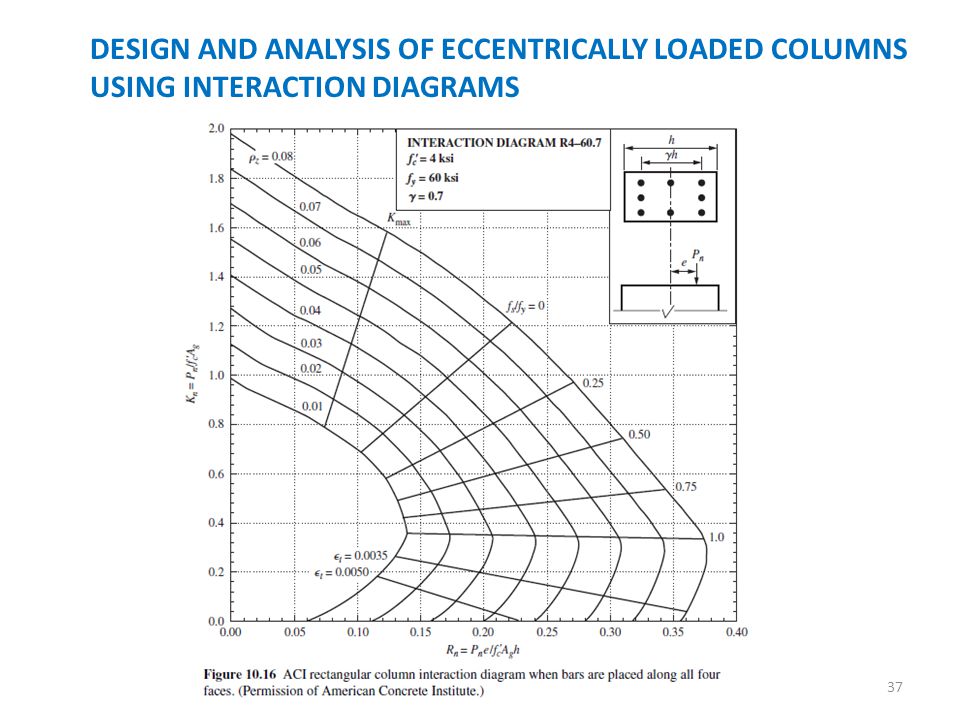
10. Using the reinforced concrete column interaction ... Using the reinforced concrete column interaction diagrams, design a short square tied column to carry a factored axial design load P. of 890 kips and a factored design moment M, of 390 ft.-kips. (That is: select the column vertical reinforcement using the interaction diagram and design the column ties). Place the longitudinal (vertical) reinforcing PDF Chapter 3 Short Column Design - Engineering 3.2.1 Column Interaction Diagrams The column axial load - bending moment interaction diagrams included herein (Columns 3.1.1 through Columns 3.24.4) conform fully to the provisions of ACI 318-05. The equations that were used to generate data for plotting the interaction diagrams were originally developed for ACI Special Publication SP-73. In ... Reinforced Concrete | PDF | Strength Of Materials | Bending COLUMN INTERACTION DIAGRAM It was observed that the use of analytical method is very complicated and requires accuracy of manipulation of algebraic equations. An option is to analyze the column by using the column interaction diagram. Interaction diagram is the graph of the axial load capacity and the moment capacity of the column of the M-P
Concrete column interaction diagram. Reinforced Concrete Columns - Interaction Diagram Question ... To produce the interaction diagram, we assume values of c and then use equilibrium equations to calculate P and M. Therefore, there is a point on the interaction curve where c is the distance from the extreme fiber to the lowest layer of steel (Case B, below). Now the concrete below the steel is in tension, the concrete is assumed to be cracked ... PDF Simplified Uniaxial Column Interaction Charts ABSTRACT :This paper presents analytical method for generating the interaction diagrams for design of reinforced concrete (RC) columns. Due to the introduction of new classes in concrete compressive strength ( ′)with somewhat different parameters for the steel grades ( 𝑦), it has become necessary to develop new interaction diagrams. Interaction Diagrams of Reinforced Concrete Columns - File ... Interaction Diagrams of Reinforced Concrete Columns version 1.0.0 (3.11 KB) by Ayad Al-Rumaithi Plots failure envelope and interaction diagrams in both x and y directions of a reinforced concrete column PDF Combined Axial and Bending in Columns - University of Alabama Loads on Columns Column Interaction Diagram. The plot of axial capacity (Pn) vs. moment capacity (Mn) is called an interaction diagram. Each point on the interaction diagram is associated with a unique strain profile for the column cross-section. An interaction diagram has three key points, as shown in the figure below.
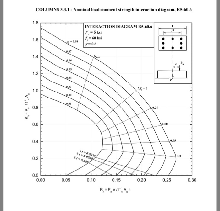
Intro to Interaction Diagrams for Concrete Columns ... This videos gives an introduction to reinforced column design by using interaction diagrams. These figures are critical for the design of reinforced concret... DIANA Tutorials | DIANA FEA fib Model code for concrete structures 2010, Creep and shrinkage, Young hardening concrete, Heat flow aspects, Flow boundary elements LOAD & BOUNDARY CONDITIONS Self-weight load, Constraint, Initial temperature, External temperature STRUCTURE magazine | Concrete Column Design: Back to the ... You may recall that an interaction diagram for a reinforced concrete column may be developed by examining a series of strain conditions at one surface of the column. These strain conditions are arbitrary, and are selected on the basis of providing the most descriptive capacity boundary that can conveniently be determined. interaction curves - STRUNET 10.10.3.4 Concrete Colum ... Concrete Colum Strength Interaction Diagram: 10.16.5.6 Conncrete Strength, f' c 5 ksi Steel Yield Strength, f y 60 ksi Clear Cover to Ties 1.5 in Column Dimensions b 10 in h 16 in Ties Bars P. No. φ P φ M φ P φ M φ P φ M φ P φ M 1 549 0 579 0 616 0 661 0 2 439 0 463 0 493 0 529 0 3 439 59 463 62 493 65 529 69 4 365 85 379 93 396 102 417 ...
Concrete Column Interaction Plot Spreadsheet - RAM - Bentley Concrete Column Interaction Plot Spreadsheet. The following VBA enabled spreadsheet allows the user to produce the N-M interaction plots and strain diagrams for a given concrete rectangular column cross section. PDF Interaction Diagram for Concrete Columns Interaction Diagrams for Concrete Columns D.D. Reynolds ,K.W. Kramer Calculate P n & M n by applying forces to free body diagram 79.95 kips 89.43 kips 489.60 kips Moment arms will be in inches, must convert to feet for desired Units. Point on curve for "Z" = .9 Figure 1.3: Column free body diagram for a "Z" of .9 1.83 kip-ft 428.33 kips ACI-318 ... ACI 318M-11 Building Code Requirements for ... - Academia.edu ACI 318M-11 Building Code Requirements for Structural Concrete (ACI 318M-11 What is a Column Interaction Diagram/Curve? - SkyCiv Column Interaction Diagram/Curve Explained. Vertical members that are part of a building frame are subjected to combined axial loads and bending moments. These forces develop due to external loads, such as dead, live, and wind loads. Simply put, an interaction diagram (or curve) displays the combinations of the acceptable moment and axial ...
DTWARE Engineering Software - Continuous Beam Analysis and ...
Manual Design Procedure for Columns with ... - StructurePoint Complete details about this procedure is provided in “Interaction Diagram – Tied Reinforced Concrete Column” design example. Using the same procedure explained in the design example (Summarized in Figure 6), a 24 in. square column with 4 #11 bars provides the following capacities: P n = 1846 = P n_req M nox = 682.8 kip-ft > M nox_req ...

Interaction Diagram for Concrete Columns - PDFCOFFEE.COM
Column Interaction Diagram - Excel Sheets Column Interaction Diagram [Spreadsheet] SP-017(14): The Reinforced Concrete Design Handbook Column Interaction Diagram May 19, 2021 Civil Books Platform 2
Data | Free Full-Text | Data for Interaction Diagrams of ...
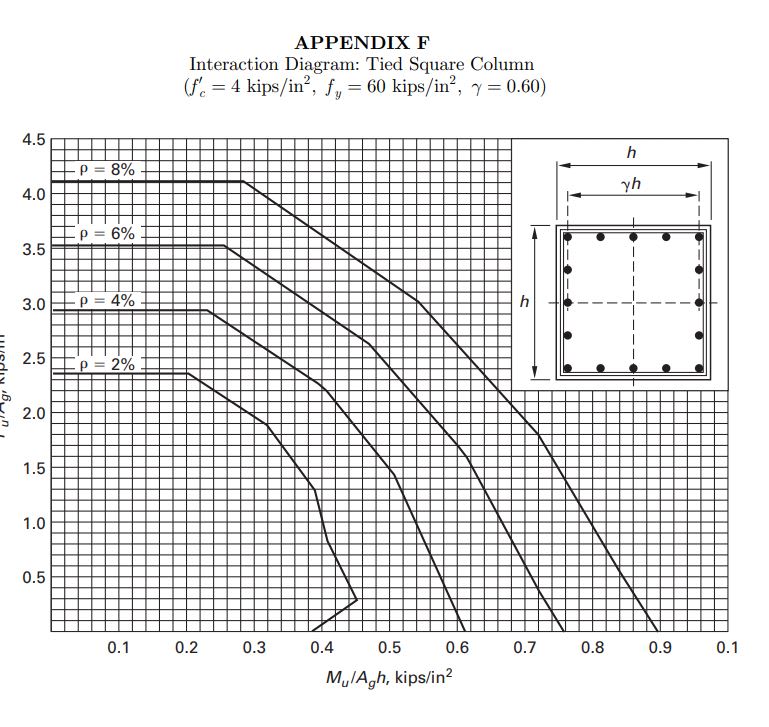
PDF Interaction Diagram - Tied Reinforced Concrete Column Interaction Diagram - Tied Reinforced Concrete Column Develop an interaction diagram for the square tied concrete column shown in the figure below about the x-axis.
What is a Column Interaction Diagram/Curve? | SkyCiv
PDF Reinforced Concrete 5150 (ACI 2.1) Design of Concrete Structures Column Design - Columns in Pure Compression • Interaction Diagram Calculations fc' = 3 7503,750 psi fy = 50,000 psi E = 28x 107 psi s 2.8 • Point 1: Zero Moment εc = .003 in/in εy = 5.0 x 104 = .001724 in/in 292.9 x 10⁷ Pu = .85 fc' Ac + As fy P = 1506 k

Interaction diagram - SAP2000 - Computers and Structures, Inc ...
Why is it that the concrete column interaction diagram is ... Why is it that the concrete column interaction diagram is not plotted in the output although track 2 was specified? If you open the file in the STAAD editor (go to the Edit menu, and choose Edit Input Command File), and go to the end of the file, you will observe the following : CLB 0.25 MEMB 1 TO 481 DESIGN ELEMENT 1 TO 456 458 TO 481

Interaction Diagrams of Hollow RC Columns - File Exchange ...
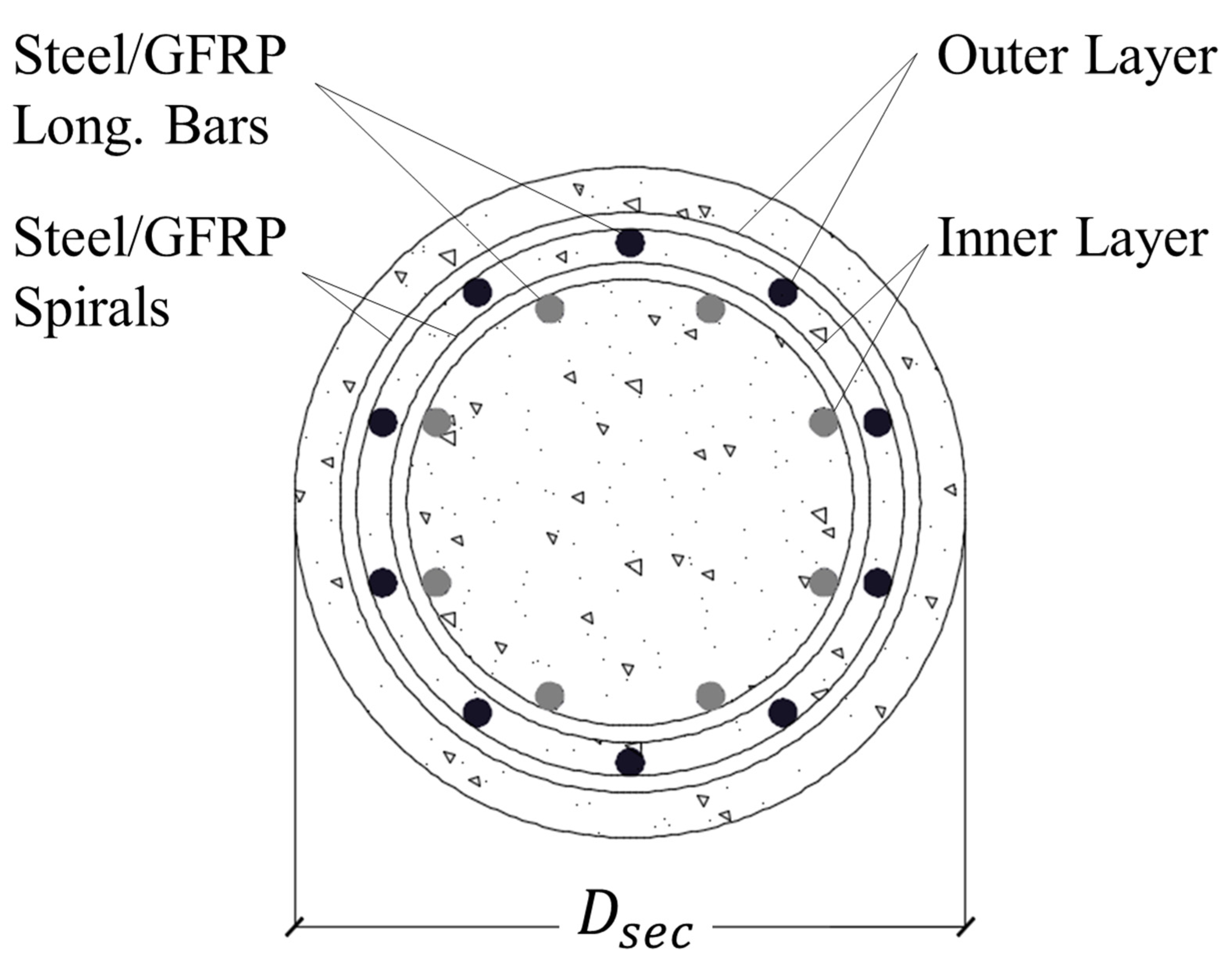
Interaction Diagram for Steel Reinforced Columns ... Download scientific diagram | Interaction Diagram for Steel Reinforced Columns from publication: Structural performance of Eccentrically loaded GFRP Reinforced concrete columns | This paper ...
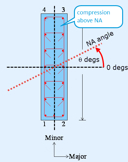
Development of Computer Aided Interaction Diagram for Bi ...
A simple method for N‐M interaction diagrams of circular ... 12 Trentadue F, Quaranta G, Marano GC. Closed‐form approximations of interaction diagrams for assessment and design of reinforced concrete columns and concrete‐filled steel tubes with circular cross‐section. Eng Struct. 2016; 127: 594- 601. 13 Turmo J, Ramos G, Aparicio AC.
![PDF] Construction of N-M Interaction Diagram for Reinforced ...](https://d3i71xaburhd42.cloudfront.net/2e30cbf79e403e1a19c6fa08814a11260abf8495/2-Figure1-1.png)
PDF] Construction of N-M Interaction Diagram for Reinforced ...
Concrete Column Interaction Diagrams - WikiEngineer Concrete Column Interaction Diagrams What is an Interaction Diagram? In short, an Interaction Diagram is a much faster way of analyzing a concrete column for large eccentricities (aka large moments). An example of a Interaction Diagram has been included in Figure 1 (click the hyperlink to expand the image).

Load and Moment Interaction Diagram for Circular Concrete ...
Interaction diagram methodology for design of FRP-confined ... This paper presents a procedure that allows the construction of a simplified axial load - bending moment interaction diagram for FRP-wrapped Reinforced Concrete (RC) columns of circular and non-circular cross-sections for practical design applications.
Interactive concrete column design | Tekla User Assistance
(PDF) An ACI Handbook The Reinforced Concrete Design Handbook ... An ACI Handbook The Reinforced Concrete Design Handbook. Williams Chiri Martínez. Enoch Maguiña. Download Download PDF. Full PDF Package Download Full PDF Package ...

Reinforced concrete short column design
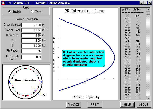
Circular Column Interaction Diagram Spreadsheet - CivilWeb The CivilWeb Circular Column Interaction Diagram Spreadsheet is an easy to use spreadsheet which can be used to design reinforced concrete circular columns in accordance with BS EN 1992. The spreadsheet completes all the calculations instantly and includes unique analysis tools allowing the designer to complete a fully optimised design in minutes.
Lect10 - Columns Interaction Diagrams
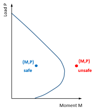
Why Use Interaction Diagrams for Column Analysis and ... A discussion on why we use interaction diagrams for design and analysis of short columns subject to axial load and bending.

Structural Design Report: COLUMN INTERACTION DIAGRAM
E-702.2(07) Interaction Diagrams for Concrete Columns This design example, "Interaction Diagrams for Concrete Columns," works through the procedure to draw an interaction diagram for a 12 x 12 in. non-slender tied (non-spiral) column reinforced with four # 8 bars bending around its x-axis. The example follows the provisions of ACI 318-05, Building Code Requirements for Structural Concrete.
Design Charts for Proportioning Rectangular Prestressed ...
PDF Slender Column Interact/On Diagrams Conventional inlcrnction diagrams are nrodified using a nondimonsionnl parnmetor characterizing colun1n slttndcr· ness. The interaction diagrams dove/oped provide • direct solution for the reinforcing rntio of si'nglo colunJns. The ap- proach presented will reduce the design time for reinforced concrete structures.
Interactive concrete column design | Tekla User Assistance
XLS University of Alabama Column Interaction Diagrams b h Material Properties Column Dimensions Reinforcement Detail Bar Size Line # # of Bars psi in k f'c fy Interaction Diagram Data Line Depth (in) k-ft Reinforcement Requirements As (in2) As,min As,max in2 Total As (in2) F for rectangular, tied columns with symmetric reinforcement Pn Mn FPn FMn

Concrete Column Design – Structural Overview | ASDIP Software
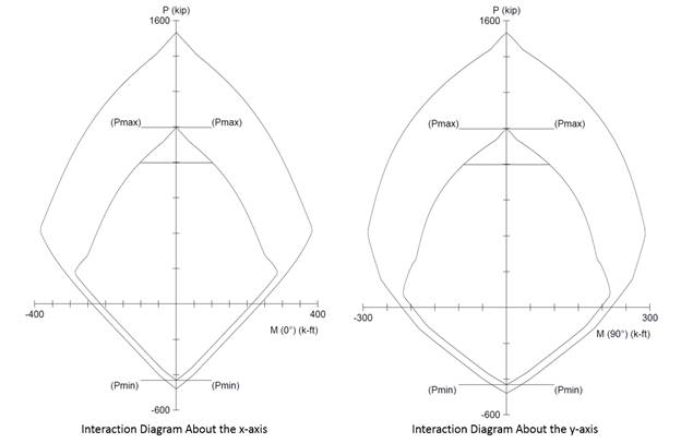
Interaction Diagram - Circular Reinforced Concrete Column ... Develop an interaction diagram for the circular concrete column shown in the figure below about the x-axis. Determine seven control points on the interaction diagram and compare the calculated values with the Reference and exact values from the complete interaction diagram generated by spColumn engineering software program from StructurePoint.

Interaction diagram methodology for design of FRP-confined ...
P-m Characteristics of Reinforced Concrete Sections Axial load-moment interaction diagrams (P-M) are used as a design aid by engineers to ensure that a reinforced concrete beam-column has sufficient capacity to carry design axial loads and moments, as well as ensuring sufficient ductility in the case of seismic design. This manuscript provides a two-part parametric study investigating the
DEVELOPMENT OF INTERACTION DIAGRAMS - ppt download
Reinforced Concrete | PDF | Strength Of Materials | Bending COLUMN INTERACTION DIAGRAM It was observed that the use of analytical method is very complicated and requires accuracy of manipulation of algebraic equations. An option is to analyze the column by using the column interaction diagram. Interaction diagram is the graph of the axial load capacity and the moment capacity of the column of the M-P

Concrete Column Design – Structural Overview | ASDIP Software
PDF Chapter 3 Short Column Design - Engineering 3.2.1 Column Interaction Diagrams The column axial load - bending moment interaction diagrams included herein (Columns 3.1.1 through Columns 3.24.4) conform fully to the provisions of ACI 318-05. The equations that were used to generate data for plotting the interaction diagrams were originally developed for ACI Special Publication SP-73. In ...
RCC column, Neutral axis, Steel ratio, Balanced failure ...
10. Using the reinforced concrete column interaction ... Using the reinforced concrete column interaction diagrams, design a short square tied column to carry a factored axial design load P. of 890 kips and a factored design moment M, of 390 ft.-kips. (That is: select the column vertical reinforcement using the interaction diagram and design the column ties). Place the longitudinal (vertical) reinforcing
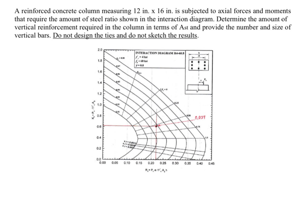
Answered: A reinforced concrete column measuring… | bartleby
Short RCC Column Performances in Different Conditions: Axial ...
What is a Column Interaction Diagram/Curve? | SkyCiv
Chapter 3 Short Column Design

Load and Moment Interaction Diagram for Circular Concrete ...
Design Charts for Proportioning Rectangular Prestressed ...
Analysis of Pu-Mu Interaction Diagram of C-Shaped Equal ...

Studies on the behavior of Reinforced Concrete Short Column ...
Reiforced Concrete Column interaction diagrams - Structural ...
Solved Using the column interaction diagrams, design a ...
What is a column interaction diagram and why it is used? - Quora
![PDF] Interaction diagram methodology for design of FRP ...](https://d3i71xaburhd42.cloudfront.net/55893d51bbe3836c8717ddd9075a13dac93e56f2/5-Figure1-1.png)
PDF] Interaction diagram methodology for design of FRP ...

Reinforced Concrete Design | Concrete design, Civil ...

Reinforced Concrete - 2 | C2-L6 | Interaction Diagram for Design of Columns

Interaction Diagram for Slender Concrete Column - Kabtamu ...
Interaction-Diagram-Tied-Reinforced-Concrete-Column ...
Document 13491554

Concrete Column Design – Structural Overview | ASDIP Software
STRUCTURE magazine | Concrete Column Design: Back to the Basics


Comments
Post a Comment