41 reversing contactor wiring diagram
PDF GI-2.0: Typical Wiring Diagrams - Rockwell Automation "WIRING DIAGRAMS" vs "LINE DIAGRAMS" Most of the diagrams in this book are shown in two ways. There is a "wiring diagram" and adjacent to it a "line diagram." Line diagrams are included because their use is becoming more widespread and we believe it is advantageous to learn to use them. Reversing Contactor Wiring Diagram - autocardesign Reversing Contactor Wiring Diagram - wiring diagram is a simplified satisfactory pictorial representation of an electrical circuit. It shows the components of the circuit as simplified shapes, and the skill and signal friends amid the devices.
Wiring Diagram For Reversing Contactor - Irish Connections Wiring Diagram For Reversing Contactor. By Irish Bella | January 6, 2020. 0 Comment. Reversing contactor definition advantages and connection diagrams electrical electronic systems forward reverse 3 phase ac motor control wiring diagram star delta main circuit 1 mcb mini circut breaker 2 fc assembly coil external interlock with power auxiliary ...
Reversing contactor wiring diagram
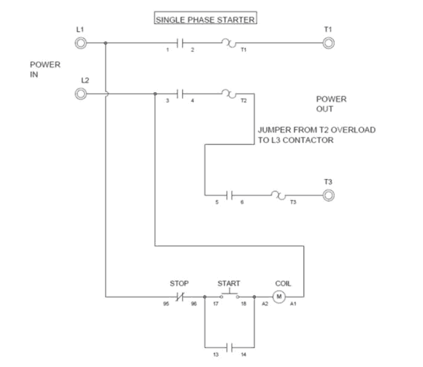
Siemen Motor Starter Wiring Diagram - Wiring Systems Single phase reversing contactor wiring diagram. It shows the elements of the circuit as streamlined shapes, and the power and signal links in between the tools. Connecting the soft starter to a wye motor inserts the SCRs directly in the line wiring, referred to as "In Line" wiring. Ac Contactor Wiring Diagram - Studying Diagrams Pdf contactor wiring diagram with timer. Contactor wiring diagram ac unit 5 Ton Goodman Heat Pump Circuit And Schematic Wiring Package Unit Diagram In Thermostat For Bard. A wiring diagram usually offers details about. Generally the magnetic coil of a contactor is designed to operate at a low voltage such as 230V AC 110V AC 24V DC etc. Ac ... PDF Reversing Contactors Open Type Version - ABB Wiring diagrams VOA 9-30M … VOA 40-30M reversing contactors, factory assembled With VM 5-1 mechanical interlocking, electrical interlocking by built-in auxiliary contacts. Power circuit Remote control For the hold-in contacts (13-14) of the KM1 and KM2 contactors, supply separately 2 x CA 5-10 type N.O. auxiliary contact (see page 3/2).
Reversing contactor wiring diagram. Contactor Coil Wiring Diagram - The Wiring Single phase reversing contactor wiring diagram. Morning gents, Im trying to find a wiring diagram for a three pole (three phase) contactor, using a 24v coil. With this sort of an illustrative manual, you are going to have the ability to troubleshoot, stop, and total your tasks without difficulty. This contactor draws about 4A at 14v. Single Phase Reversing Contactor Wiring Diagram - Wiring ... Single phase reversing contactor wiring diagram. Why 3 phase ac instead of single phase. In the above one phase motor wiring i first connect a 2 pole circuit breaker and after that i connect the supply to motor starter and then i do cont actor coil wiring with normally close push button switch and normally open push button switch and in last i do connection between capacitor. Single Phase Contactor Wiring - Entries - Forum - Industry ... I have a customer with a single phase, dual voltage (115/230V) motor. He has a Siemens 43CP12FB reversing contactor and a 3UB8823-4DW2 overload. With the supplied wiring diagrams and/or searching on Siemens website, I cannot find out how this should wired. His motor has 6 leads, and to reverse direction, L1 & L2 are swapped for T5 & T8. Wiring Diagrams from Sprecher - Schuh Wiring Diagrams & Standard Electrical Schematics Access Our Easy-to-Use Diagrams, When You Need Them. Standard Contactor & Starter Drawings. CA7/CA6 Full Voltage Non-Reversing Contactors. Drawing # Description PDF File DWG File; WS-100-01: CA7-9..97 w/ D7 Pilot Device Kits, Three Phase: WS-100-11A: CB7-9..97 w/ Local Devices, Single Phase:
Reversing Contactor Switch Module - SEW-EURODRIVE Operating Instructions – Reversing Contactor Switch Module. 3. Table of contents. 1. General information. ... Wiring diagram.28 pages reversing contactor diagram - Wiring Diagram Line Reversing Contactor Definition Advantages And Connection Diagrams. Reversing Contactor Assembly Ac Coil External Interlock With Power And Auxiliary Wiring 9a Ac3 In 4kw Voltage 230vac 50 60hz Lovato Electric. Type Of Contactor For Direction Change Single Phase Im Electrical Engineering General Discussion Eng Tips. Freedom Reversing Contactor Nema Size 4 - Wiring Diagram THE INFORMATION ON THIS DRAWING IS THE PROPERTY OF EATON CORPORATION, IS DISCLOSED N CONFIDENCE AND IS NOT TO BE REPRODUCED, USED OR DISCLOSED EXCEPT FOR ...1 page Single Phase Reversing Motor Wiring Diagram - U Wiring A wiring diagram is a simplified conventional pictorial representation of an electrical circuit. It shows the components of the circuit as simplified shapes and the gift and signal friends between the devices. To reverse rotation on a single phase capacitor start.
3 Phase Forward Reverse Switch Wiring Diagram | contactor ... The forward reverse motor control is used in a system where forward and backward or upward and downward movement in the operation is needed. Forward and Reve... Forward/Reverse Control Circuits - Basic Motor Control Forward/Reverse control circuit. When designing the control schematic for forward / reverse circuits, we start with the standard. three-wire circuit. , add a second normally open pushbutton, and add a holding contact branch for the second coil. A single stop button is sufficient to disable the motor in both directions. Reversing contactors - Carts Unlimited One Reversing Contactor, one F&R rocker switch and one F&R switch housing shown. Mounting hardware included for contactor and switch. And mount bracket supplied where needed. Installer provides 16g wire for switch and a few crimp on connectors. Simple cable and wire diagram is clear and easy to follow. 1-2 hour install Magnetic Contactor Wiring Diagram Pdf - The Wiring Motor starter schematic and wiring diagram. (excluding MSO-T and TH-T type) Reversing type is also down-sized. The terminals of these coils are arranged on the contactor with simple wiring. A wiring diagram is a simplified traditional pictorial representation of an electrical circuit.
Albright Equivalent 24vdc 100a Reversing Contactor Dc88-282p ...
PDF SW202 / SW182 & DC182 Wiring Diagram For Series Motors ... Reversing Contactor Position the diode so that the stripe and red heat shrink is on the switch side of the circuit, or hot side. The picture above shows one side of a reversing contactor. Repeat on the other side. Stripe Red Black Red Black SW202 / SW182 & DC182 Wiring Diagram For Series Motors & Permanent Magnet Brushed Motors S1 S2 S1 S2 M- M ...
575 Series - Motor Reversing Contactors On Struthers-Dunn
Reversing contactor: Advantages and Connection diagrams Below you can see the power and control circuit connection diagrams of reversing contactors. Let's explain how they work: 1-Wire up the first and second contactor's coils to separate pushbuttons. The second pushbutton has one side jump to the other pushbutton 's power source and the second contactor's A1 is jumped with the first ...
275 Series - Motor Reversing Contactors On Struthers-Dunn
Contactor Wiring Diagram - Wiring Diagram Contactor Wiring - Contactor Wiring Diagram. Wiring Diagram includes numerous in depth illustrations that present the relationship of varied products. It includes guidelines and diagrams for different types of wiring techniques along with other things like lights, home windows, etc. The guide features a large amount of sensible tips for ...
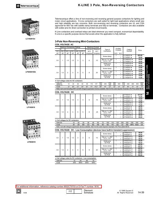
K-Line 3 Pole, Non-Reversing Contactors - TE-EPC-LPC General
Reverse Contactors - ElectricScooterParts.com 24 Volt 150 Amp Motor Reversing Contactor 24 Volt DC 150 Amp motor reversing contactor. Coil power consumption 8 Watts. Has no-load rated make or break contacts so it needs to be used with a speed controller and the vehicle should be stopped before switching between forward, park, and reverse directions. Applies electronic braking to the motor when the switch is in the park position which ...

DC Grab Motor Starter Relay Factory, Lieferanten und ...
wiring diagram reversing contactor - Wiring Diagram Wiring Diagram Reversing Contactor. Reversing contactor definition advantages and connection diagrams assembly ac coil external interlock with power auxiliary wiring 9a ac3 in 4kw voltage 230vac 50 60hz lovato electric electrical electronic systems forward reverse 3 phase motor control diagram star delta main circuit 1 mcb mini circut breaker 2 ...

Forward-Reverse Control
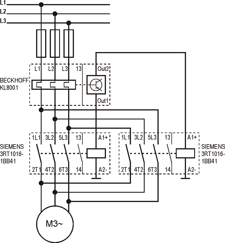
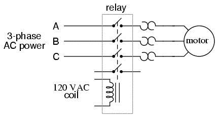
Non-Reversing vs. Reversing Contactor - CR4 Discussion Thread The schematic (Wiring diagram) of a reversing 3-phase contactor assembly is above. A 3-phase standard non-reversing contactor wiring diagram is shown below, and has been called "Relay". The contactor control voltages may be mains voltage or a special Control Voltage, often 24V DC is used as a standard Voltage for control systems in industrial ...

Schneider Electric LC2K Wendeschütz, 3 -polig , 24 V ac Spule / 9 A, 4 kW, 600 V ac, 1 Öffner, Umkehrend, TeSys K
PDF Basic Wiring for Motor Contol - Eaton Wiring diagrams, sometimes called "main" or "construc-tion" diagrams, show the actual connection points for the wires to the components and terminals of the controller. They show the relative location of the components. They can be used as a guide when wiring the controller. Figure 1 is a typical wiring diagram for a three-phase mag-

Wiring Diagram Forward-Reverse for 3 Phase Motor - My ...
Allen Bradley Reversing Contactor Wiring Diagram Wiring Diagrams ww introduction This booklet has been prepared as a guide to some of the useful ways Allen-Bradley's manual and magnetic across-the-line starters may be applied. It will also serve as a useful The Bulletin RS manual reversing starters and the.Google Answers: I need to know which contactor or starter to use to control my ...

ARI Armaturen ARI-PREMIO Plus EN User Manual | Page 24 / 50
Contactor Wiring Diagram Pdf - U Wiring Contactor wiring diagram pdf. IEC Contactors 41-42 IEC Contactors and Auxiliary Contact Blocks 41 Input Modules and Reversing Contactors 42 Type S. I know how relays work in general. You will be in a position to understand exactly once the assignments ought to be completed that makes it much simpler to suit your needs to correctly manage your ...

Reversing contactor: Definition, Advantages and Connection ...
Allen Bradley Reversing Contactor Wiring Diagram When applying these diagrams, it is well to. Jun 11, · I am trying to wire a single phase motor to a reversing contactor. the incoming power is VAC, my control circut is 24VAC. i understand the control part of it but what im trying to figure out is how to wire the motor to the contactor so as to reverse direction of the motor.
Wiring of a contactor LC1D091o to a daynight switch | DIY ...
PDF Wiring Diagram Book - Daltco Input Modules and Reversing Contactors 42 Type S AC Magnetic Starters.....43-50 Class 8536 43-50 8538 and 8539 45,49 1-Phase, Size 00 to 3 43 2-Phase and 3-Phase, Size 00 to 5 44 3-Phase, Size 6 45 3-Phase, Size 7 46 3-Phase Additions and Special Features 47-50 ... WIRING DIAGRAM. M A1 A2 M .
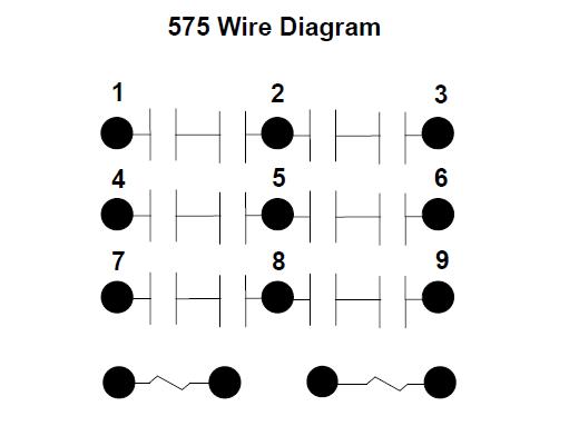
575 Series - Motor Reversing Contactors On Struthers-Dunn
Wiring Diagrams for Contactors, Motor Starters, Relays, & More 3 Pole Contactor without base contact 4 Pole Contactor with 4 N.O. Power Poles 4 Pole Contactor with 2 N.O./2 N.C. Power Poles 3 Pole Reversing Contactor Set. 4 Pole Control Relay with 4 N.O. contacts 4 Pole Control Relay with 3 N.O. / 1 N.C. contacts 4 Pole Control Relay with 2 N.O. / 2 N.C. contacts. 3 Phase Motor Contactor/Overload Relay Starter
Reversing Contactors: Dissected and Explained
Contactors - Reversing - EVDrives Reversing Contactor (White Rogers 586) Diagram for Series Motors.pdf. Alltrax AXE Reverse With Plug Brake Wire Diagram. Doc100-048-B_DWG-AXE-PlugBrk-Rev-wire-dia.pdf. Winch Motor With DC88 Reversing Contactor. DC88WiringDiagram.pdf. General Reversing Contactor Wiring Diagram. ReversingContactorDiagram.pdf.
50A DC Reversing Contactor, 12V/24V/36V/48V, 2NO & 2NC
PDF Reversing Contactors Open Type Version - ABB Wiring diagrams VOA 9-30M … VOA 40-30M reversing contactors, factory assembled With VM 5-1 mechanical interlocking, electrical interlocking by built-in auxiliary contacts. Power circuit Remote control For the hold-in contacts (13-14) of the KM1 and KM2 contactors, supply separately 2 x CA 5-10 type N.O. auxiliary contact (see page 3/2).

Interlocking Methods for Reversing Control (Basic Control ...
Ac Contactor Wiring Diagram - Studying Diagrams Pdf contactor wiring diagram with timer. Contactor wiring diagram ac unit 5 Ton Goodman Heat Pump Circuit And Schematic Wiring Package Unit Diagram In Thermostat For Bard. A wiring diagram usually offers details about. Generally the magnetic coil of a contactor is designed to operate at a low voltage such as 230V AC 110V AC 24V DC etc. Ac ...

Full voltage reversing 3-phase motor diagram | Electrical ...
Siemen Motor Starter Wiring Diagram - Wiring Systems Single phase reversing contactor wiring diagram. It shows the elements of the circuit as streamlined shapes, and the power and signal links in between the tools. Connecting the soft starter to a wye motor inserts the SCRs directly in the line wiring, referred to as "In Line" wiring.

DC182B-1 Albright 12V Motor-reversing Intermittent Solenoid

36v txt sr48500 sw202 7126 motor. No reverse intermittent ...

How To Wire Contactor And Overload Relay - Contactor Wiring ...

Circuits, Formulas and Tables Electrical Engineering - Basic ...

LC2K0901F7 Schneider Electric - Distributors, Price ...

Motor Forward Reverse Wiring Diagram | Elec Eng World ...
3 Phase Motor Contactor Wiring Diagram & Guide | Springer ...

Electrical Wiring Diagram Forward Reverse Motor Control and ...
Beckhoff Information System - English
SW202 400A-Cont. Reversing (Change-over) Contactor Kit

Forward Reverse Motor Control Diagram For 3 Phase Motor

SIRIUS_IC10_Switching_Devices ...

PDF) Schneider Electric Wiring Diagram Book | Engineer Bilal ...
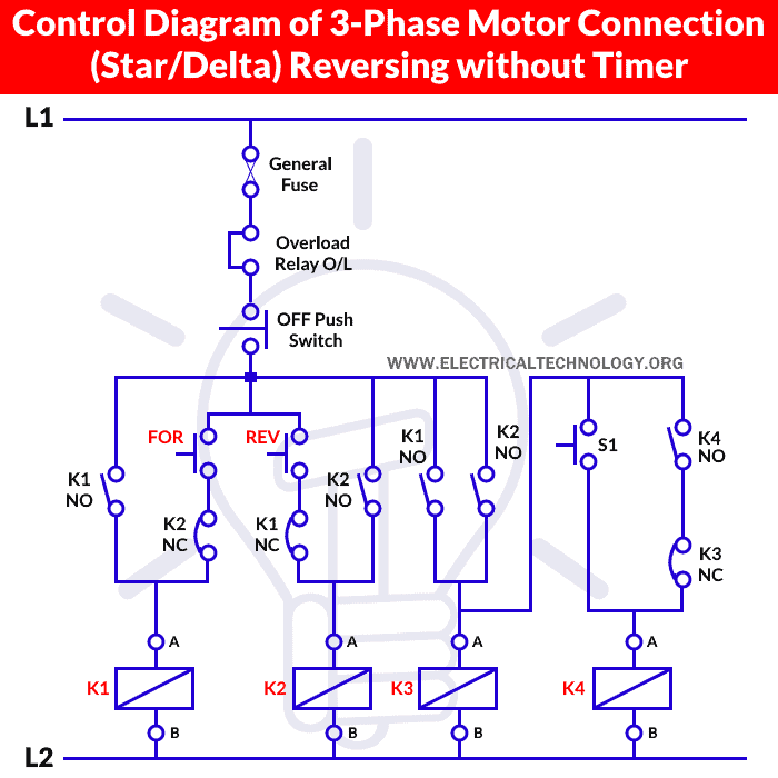
Three Phase Motor Star/Delta Reverse & Forward without Timer
W POWER AND AUXILIARY CONTACTORS W MODULAR CONTACTORS w ...

5.3. Reversing Contactor Circuits

Forward Reverse Starter With Timer 3 Phase Motor Wiring Diagram
Wiring Schematic--Tapping pack for Reversing Contactor | DIY ...

FAQ02046 of Solid-state Relays FAQ
Raymond 賴

REVERSING CONTACTOR ASSEMBLY, AC COIL, EXTERNAL INTERLOCK ...

Power contactors for switching motors - Industry Mall ...
DC88P 24VDC 100A 400A(NC) Normally Closed DC Contactor in ...

5. Contactor Circuits

Power contactors for switching motors - Industry Mall ...


Comments
Post a Comment