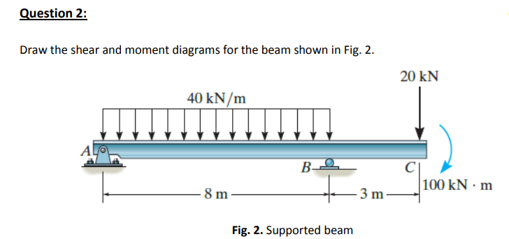
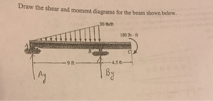
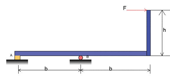
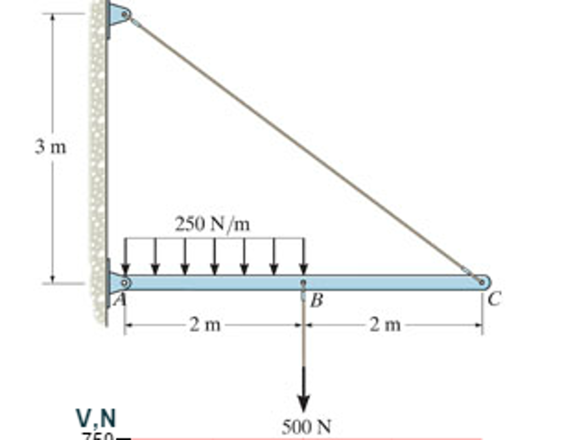
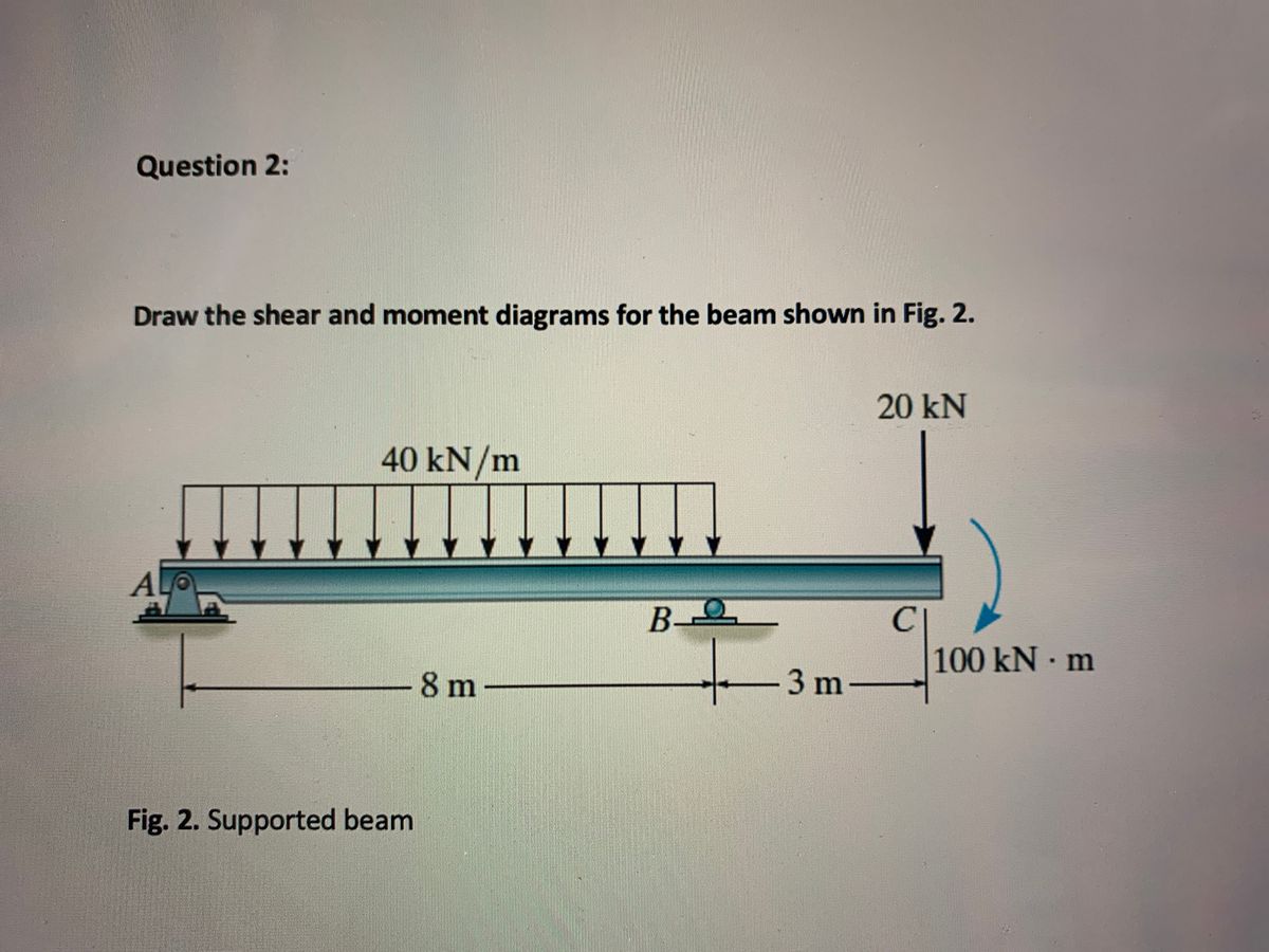
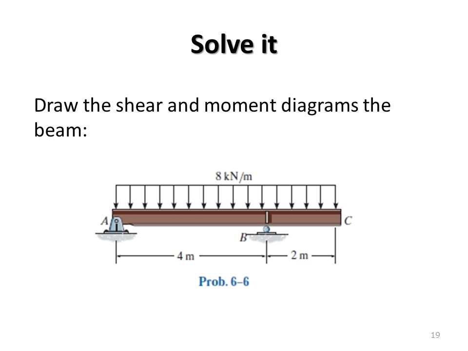
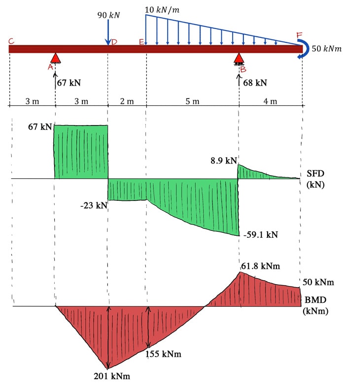
43 draw the shear diagram for the beam.
How to draw the shear-force and bending-moment diagrams ... Answer: Start with the shear force diagram. Starting from the unsupported end of the cantilever you would start with zero shear force at the point where you first encounter applied load as you move today the fixed support. The shear force will increase linearly as you continue to move toward the ... Draw the shear and moment diagrams for the cantilevered beam The steps required to plot the shear force and bending moment diagrams are: 1. Determine all the reactive forces and couple moments acting on the beam and resolve all of them into components acting perpendicular and parallel to the beam's axis. 2.
Solved Problem 6.29 Draw the shear diagram for the beam ... View the full answer Transcribed image text: Part A Draw the shear diagram for the beam. Begin by placing the lines of discontinuity. Place the appropriate function between the lines of discontinuity, ensuring the endpoints have the correct values. Note - Make sure you place only one vertical line at places that require a vertical line.

Draw the shear diagram for the beam.
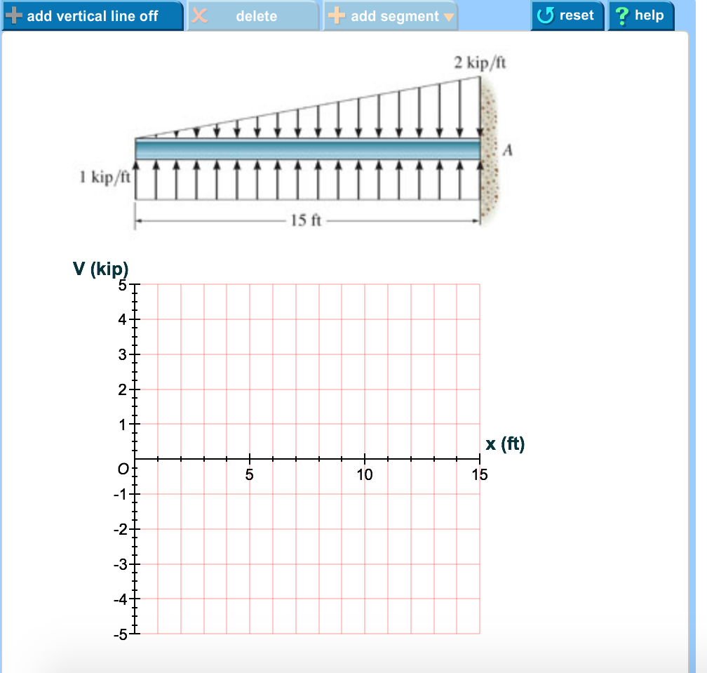
Answered: Draw the shear diagram for the beam… | bartleby Draw the shear diagram for the beam Click on "add vertical line ofr to add discontinuity lines. Then click on "add segment" button to add functions between the lines. Note 1- Make sure you place only one vertical line at places that require a vertical line. Shear Force & Bending Moment Diagram of Cantilever Beam ... Shear force on cantilever beam is the sum of vertical forces acting on a particular section of a beam. While bending moment is the algebraic sum of moments about the centroidal axis of any selected section of all the loads acting up to the section. Example: Draw shear force and bending moment diagrams of the cantilever beam carrying point loads. Draw The Shear And Moment Diagrams For The Overhang Beam. Shear and Moment Diagrams Procedure for analysis - the following is a procedure for constructing the shear and moment diagrams for a beam. The change in the shear force is equal to the area under the distributed loading. If the distributed loading is a curve of degree n, the shear will be a curve of degree n+1.
Draw the shear diagram for the beam.. Draw the shear and moment diagrams for the cantilever beam ... Mechanics of Materials - Instructor Solutions Manual [EXP-4667] Draw the shear and moment diagrams for the cantilever beam. Answered: Draw the shear and moment diagrams for… | bartleby Draw the shear and moment diagrams for the cantilever beam shown and determine the maximum absolute value of the shear and bending moment. Indicate the degree of each curve. You may use the method of sections, area method, or both. 15 kN/m 8 kN 5 kN/m A В 20 kN/m 8 kN/m E 2 m →e 3 m 6 m. How to Calculate and Draw Shear and Bending Moment Diagrams These instructions will help you to calculate and draw shear and bending moment diagram, as well as draw the resulting deflection. Knowing how to calculate and draw these diagrams are important for any engineer that deals with any type of structure because it is critical to know where large amounts of loads and bending are taking place on a beam so that you can make sure your structure can ... Can you draw the shear force and bending moment diagrams ... Answer (1 of 2): EDIT 2020-09-14 Without explaining all the calculus to prove it, a simple rule of thumb is: 1. the change in shear = -(area under the load curve (w)) 2. slope of the V curve = -(w) 3. slope of the M curve = V 4. the change in M = area under the V curve. Here's how I got my numb...
[Solved] For the beam and loading shown draw the shear and ... Are you looking for the beam and loading shown draw the shear and bending moment diagrams? then you are at the right place on the web. Beams come with different kinds and different types of loading on them. Hence, Submit your questio n and get solved within a few hours. PDF Draw the shear force and bending moment diagrams for the ... (Cambridge)7.12Draw the bending moment and shearing force diagrams for the beam shown. The beam is supported horizontally by the strut DE, hinged at one end to a wall, and at the other end to the projection CD which is firmly fixed at right angles to AB. The beam is freely hinged to the wall at B. The masses of the beam and strut can be neglected. 6.2 Shear/Moment Diagrams - Engineering Mechanics: Statics Draw the shear force and bending moment diagrams for the cantilever beam supporting a concentrated load of 5 lb at the free end 3 ft from the wall. 1. Draw a FBD of the structure Shear Force Diagram - How to Draw a SFD - mechGuru Start drawing shear force diagram from any of the extreme ends. Draw a vertical line of same length as the value of applied force at the point. If force acting on the point is downward then the vertical line should go downward or else upward.
329 6–1. Draw the shear and moment diagrams for the shaft ... The free-body diagram of the beam's right segment sectioned through an arbitrary point shown in Fig.a will be used to write the shear and moment equations of ...143 pages Shear Force and Bending Moment Diagram for Simply ... To find out Shear Force, first, we will calculate R a and R c. Beam is simply supported ∑M a = ∑M c = 0. Let us consider ∑M a = 0. 6*4 - R c *8 = 0 (Clockwise bending moment will be positive and Anti-Clockwise will be negative) Rc = 24/8 Rc = 3 As we can see from the figure load is applied in the center, so both reactions will be the same. PDF A Practical Graphical Approach for Drawing Shear Force and ... drawing the S/B diagrams. [1,2]The method of sections can be used to determine fully the shear force and bending moment at any cross-section of beams and to draw the S/B diagrams. When there are several external forces on a beam, the beam must be divided into several segments. The method of sections will be used repeatedly in each segment. Draw the shear diagram for the beam. follow the sign ... Part A. Draw the shear diagram for the beam. Follow the sign convention. (Figure 1) Click on "add vertical line off" to add discontinuity lines. Then click on "add segment" button to add functions between the lines. Note 1 - You should not draw an "extra" discontinuity line at the point where the curve passes the x-axis.
Draw the shear and moment diagrams for the beam. | Study.com
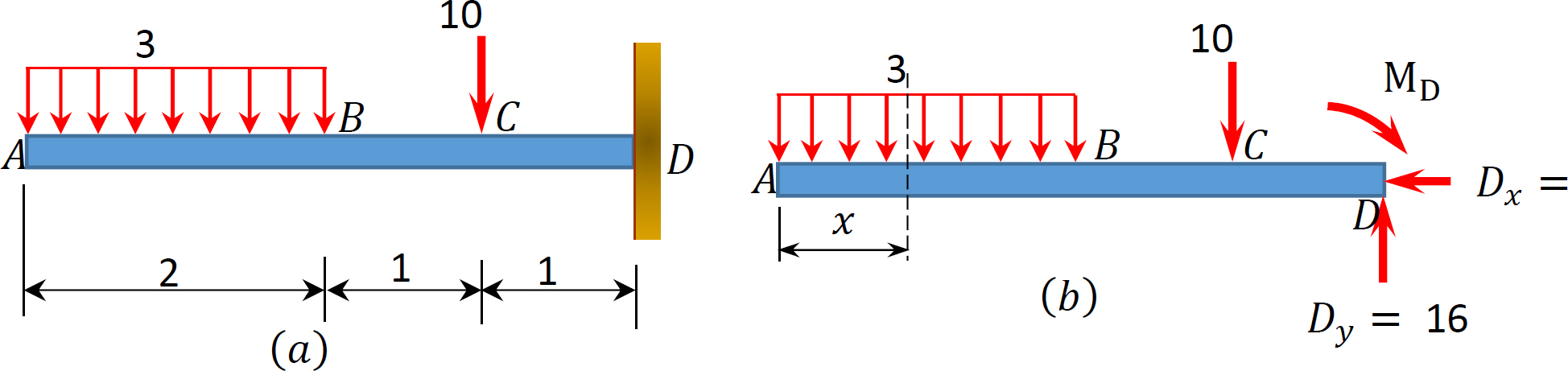
PDF Chapter 4 Shear and Moment In Beams - ncyu.edu.tw The simply supported beam in Fig. (a) carries two concentrated loads. (1) Derive the expressions for the shear force and the bending moment for each segment of the beam. (2) Sketch the shear force and bending moment diagrams. Neglect the weight of the beam. Note that the support reactions at Aand Dhave been computed and are shown in Fig. (a).
1.4: Internal Forces in Beams and Frames - Engineering LibreTexts
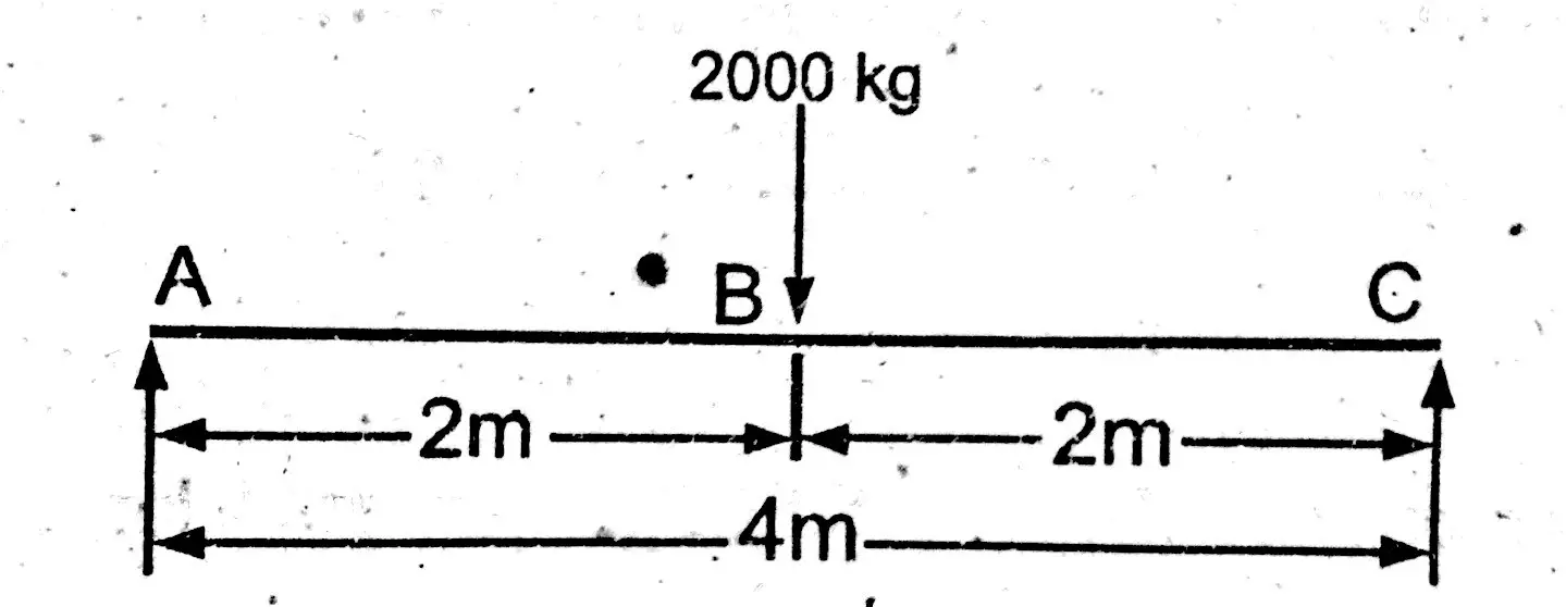
How to Draw Shear Force & Bending Moment Diagram | Simply ... Draw shear force and bending moment diagram of simply supported beam carrying point load. As shown in figure below. Solution First find reactions of simply supported beam. Both of the reactions will be equal. Since, beam is symmetrical. i.e., R1 = R2 = W/2 = 1000 kg. Now find value of shear force at point A, B and C.
A Practical Graphical Approach for Drawing Shear Force and ...
Draw the Shear and Moment diagrams for the beam- With ... Draw the Shear and Moment diagrams for the beam 1) Calculate the shear force and bending moment for the beam subjected to concentrated load as shown in the figure. Also, draw the shear force diagram (SFD) and the bending moment diagram (BMD). Solution; Free body diagram of the given figure, Taking moment about point B, R Ay x 4 - 20 x 2 = 0
Answered: Draw the shear diagram for the beam.… | bartleby
Answered: 2. Draw the shear and moment diagrams… | bartleby Draw the shear and moment diagrams for the beam system shown below. (Use area method) 400 N/m 200… A: Given Beam is : Simply supported beam. Total Span of the beam = 6m There is A UDL + UVL on the span…
Solved] Draw the shear force bending moment diagrams of the ...
Shear force and bending moment diagram - SlideShare Sections for Shear Force and Bending Moment Calculations: Shear force and bending moments are to be calculated at various sections of the beam to draw shear force and bending moment diagrams. These sections are generally considered on the beam where the magnitude of shear force and bending moments are changing abruptly.
How to Draw Moment Diagrams | ReviewCivilPE
Mechanics Map - Shear and Moment Diagrams The shear diagram will plot out the internal shearing forces within a beam, or other body that is supporting multiple forces perpendicular to the length of the beam or body itself. The shear and moment diagrams are both used primarily in the analysis of horizontal beams in structures, such as floor joists, ceiling joists, and other horizontal ...
Hibbeler R.C. Structural Analysis
Answered: Draw the shear and moment diagram for… | bartleby Solution for Draw the shear and moment diagram for the beam. close. Start your trial now! First week only $4.99! arrow_forward. learn. write. tutor. study ... Draw the shear and moment diagram for the beam. Question. Draw the shear and moment diagram for the beam. Transcribed Image Text: 3m A. Expert Solution.
Answered: Draw the shear and moment diagrams for… | bartleby
Solved Draw the shear diagram for the beam. Draw the ... Draw the shear diagram for the beam. Draw the moment diagram for the beam. Note - Make sure you place only one vertical line at places that require a vertical line. If you inadvertently place two vertical lines at the same place, it will appear visually correct because the lines overlap, but the system will mark it wrong.
Mechanics of Materials Chapter 4 Shear and Moment In Beams
Shear Force and bending moment diagram - ExtruDesign Steps to draw Shear force and Bending moment diagrams In SFD and BMD diagrams Shear force or Bending moment represents the ordinates, and the Length of the beam represents the abscissa. Consider the left or the right portion of the section. Add the forces (including reactions) normal to the beam on the one of the portion.
Chapter 4: Internal Forces in Beams and Frames” in ...
Draw the shear and bending moment diagrams for the beam ... The shear force diagram for the beam is as below: The shear force and bending moment values at different locations of the beam are calculated. The shear force diagram and bending moment diagrams are is drawn by plotting the beam length along the x -axis and magnitudes of the shear force and bending moments along the y -axis. Step 4 of 13 5.7.a)

Draw the shear diagram and the moment diagram for the beam400 ...
Draw The Shear And Moment Diagrams For The Overhang Beam. Shear and Moment Diagrams Procedure for analysis - the following is a procedure for constructing the shear and moment diagrams for a beam. The change in the shear force is equal to the area under the distributed loading. If the distributed loading is a curve of degree n, the shear will be a curve of degree n+1.

How to Calculate and Draw Shear and Bending Moment Diagrams ...
Shear Force & Bending Moment Diagram of Cantilever Beam ... Shear force on cantilever beam is the sum of vertical forces acting on a particular section of a beam. While bending moment is the algebraic sum of moments about the centroidal axis of any selected section of all the loads acting up to the section. Example: Draw shear force and bending moment diagrams of the cantilever beam carrying point loads.
Solved) - Draw the shear and moment diagrams for the beam ...
Answered: Draw the shear diagram for the beam… | bartleby Draw the shear diagram for the beam Click on "add vertical line ofr to add discontinuity lines. Then click on "add segment" button to add functions between the lines. Note 1- Make sure you place only one vertical line at places that require a vertical line.
Draw the shear and moment diagrams for the beam loaded by th ...
Shear Diagram - Beam with 3 supports | Physics Forums

Draw the shear diagram for the beam. Follow the sign ...
Beams – SFD and BMD

Determine Reactions Draw Shear Bending Moment Diagrams Beams ...

Statics 7.61 - Draw the shear and moment diagrams for the beam.
PROBLEM 5.1
Mechanics of Materials Chapter 4 Shear and Moment In Beams
Solved Problem 7.75 Part A Draw the shear | Chegg.com
Answered: Draw the shear and moment diagrams for… | bartleby
How to Draw Shear Force & Bending Moment Diagram | Simply ...

Draw the shear and moment diagrams for the cantilevered beam
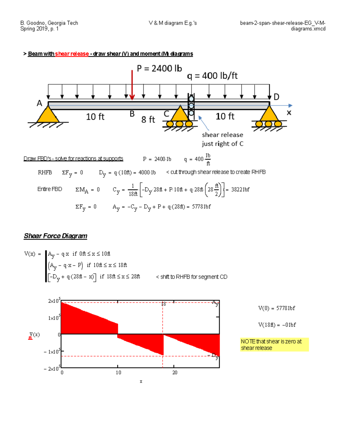
Beam-2-span-shear-release-UNIF-load EG V-M-diagrams - COE ...
Answered: Draw the shear diagram for the beam.… | bartleby

Drawing Shear Force, Bending Moment Diagram » File Exchange ...
Structural Axial, Shear and Bending Moments

Part A Draw the shear diagram for the beam. Part B Draw the ...
Bending Shear and Moment Diagram, Graphical method to ...

Drawing Shear and Moment Diagrams for Beam
How to Calculate Bending Moment Diagram? | SkyCiv

Draw the shear force diagram and bending moment diagram for ...

Draw the shear and moment diagrams for the cantilever beam in ...
Shear Load and Bending Moment Diagrams

Moment Diagrams Constructed by the Method of Superposition ...

329 6–1. Draw the shear and moment diagrams for ...

How to Calculate and Draw Shear and Bending Moment Diagrams ...
Solved Draw the shear diagram for the beam. Draw the moment ...

Draw The Shear Diagram For Beam | Beams, Bending moment ...
The Ultimate Guide to Shear and Moment Diagrams ...
Solved 7.93 Draw the shear diagram for the beam. | Chegg.com


Comments
Post a Comment