42 amp power step wiring diagram
Amplifier Wiring Diagrams: How to Add an ... - Crutchfield This wiring diagram shows how a full-blown car audio system upgrade gets wired in a car. The system depicted includes new speakers, an aftermarket receiver, a 4-channel amp for the front and rear pairs of full-range speakers, and a mono amp for a subwoofer. The extra gear you'll need for wiring the amps includes: a dual amplifier wiring kit How to Wire a 50-Amp Plug for Welder? – SelectSafety.net 15/12/2021 · Step 6: Test the new 50-amp welder plug. Now it’s time to test the plug to see if it is functioning properly. Turn on the main power and circuit breaker at the breaker box. Plug your welder into plug. Then press the power button on the welder and run a test weld on a small piece of metal. If all is OK then just screw down the outlet cover and ...
AMP Research - Power Running Boards & Truck Bed Steps ... Available in 2022 PowerStep SmartSeries™ now offers in-app flexibility to retract and deploy power running board and LED lights. SEE DETAILS. BedStep® - Bumper Step (112) Starting At $290. Strong and rugged, this non-slip, retractable bumper step quickly flips down with the nudge of a foot providing a faster, easier and safer way to load or ...
Amp power step wiring diagram
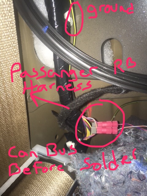
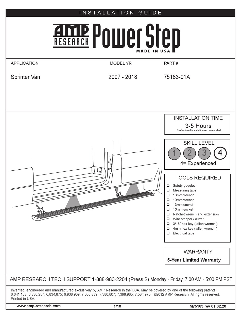
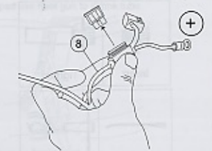
PDF TM - AMP Research 2004 model shown Some previous year models require that the ORANGE and WHITE wires be reversed (See wire diagram) Plug in (both sides) 3 2 Open doors to extend arm (if not already extended) TORQUE 10 ft-lbs (13.5 N m) 2 1 10 Attach step Slide mounting T-nut into position 27" 65" Looking for wiring diagram pictures of the AMP power step Can anyone give me info or pictures of the wiring of the AMP power step in the passenger kick panel for a 2020 Gladitor The install directions are useless. thanks frank PDF INSTALLATION TIME SKILL LEVEL 1 2 3 4 - AMP Research Loosely loop tie-wraps around large bundle of wires behind battery in engine compartment. Insert controller into tie-wrap loops and cinch down securely. The tie-wraps should cinch down into channels on controller surface. Connect power leads from Controller, Red to positive battery terminal and Black to the vehicle body ground as shown.
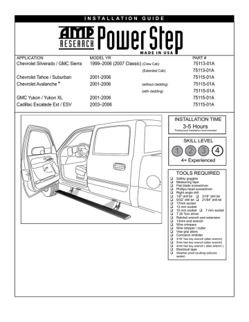
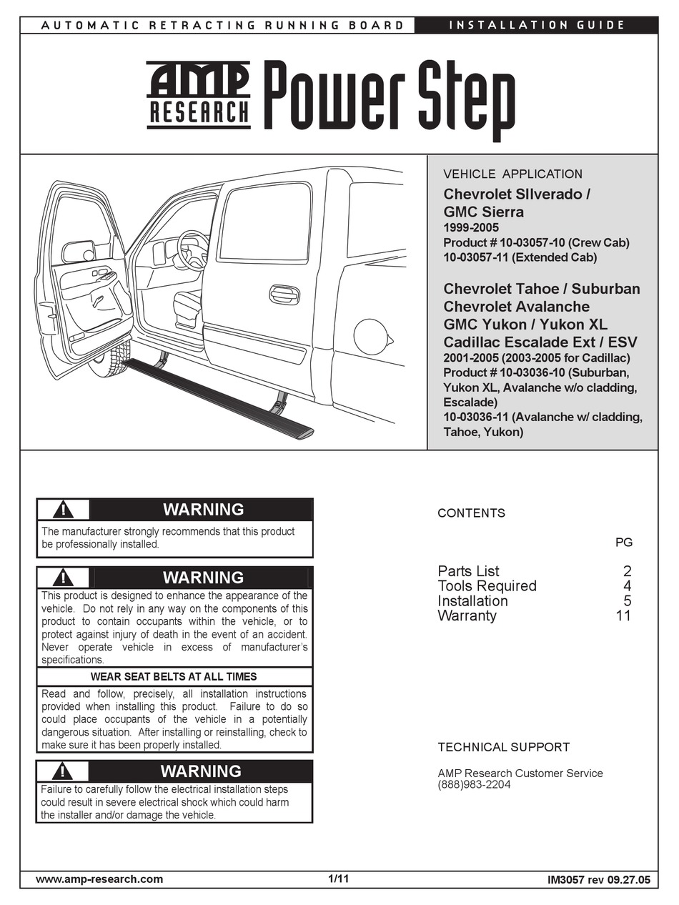
Amp power step wiring diagram. PDF Amp Research Power Step - Gmc / Chevrolet Installation Guide AMP RESEARCH POWER STEP - GMC / CHEVROLET 10 12 AVOID DRILLING THROUGH WIRES. READ THE ABOVE CAUTION NOTE! Center the upper support mount and drill 1/8" starter holes, then remove mount and drill 3/16" holes. Drill through first layer of sheet metal only. Attach with #14 sheet metal screws. Jeep Gladiator AMP Research Power Steps XL - YouTube In this video, I go through the process of installing the new AMP Research Power Steps XL onto my 2020 Jeep Gladiator Rubicon in preparation for my 4.5" Skyj... PDF SKILL LEVEL 1 2 3 4 - AMP Research AMP RESEARCH POWERSTEPTM- CHEVROLET / GMC 10 This is how the front passenger side linkage should look when installed. The Shield (21) should be installed as shown below, marked 'P' for passenger and 'D' for driver side, use 3 bolts (22) per side of the vehicle. The shield should be rotated counterclockwise, then tightened to 4 ft-lbs. Solar Panel Wiring Diagram and Installation Tutorials In your suggested scheme, there are two power converters in the path from Solar panels to the batteries, whereas in the other model that you mentioned, one power converter, i.e. the charge controller is only one in the path between the solar panels and battery. The losses in the second power converter is avoided in the system. When you need AC ...
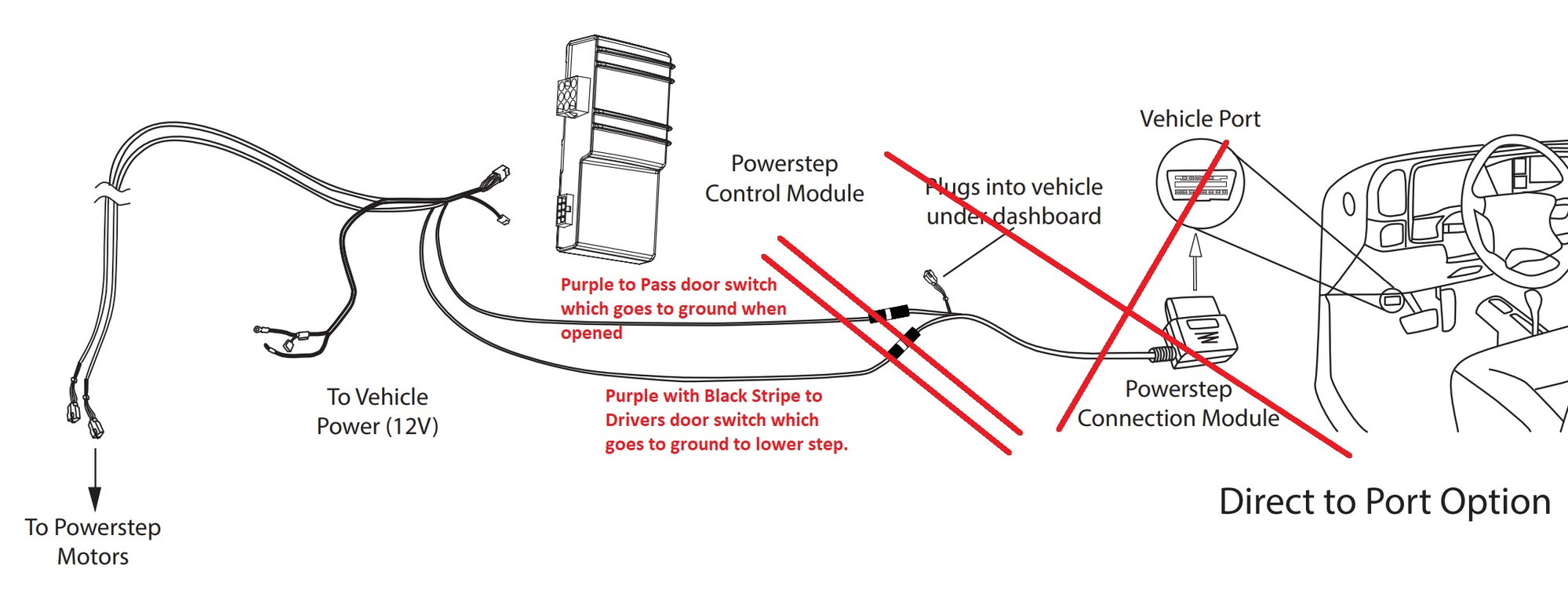
How to Install Amp Research PowerStep ... - AmericanTrucks Locate the brown plug in doors and using supplied Posi-Tap™ connector, splice into trigger wire. Drivers side: Grey / Black wire Passengers side: Tan / White wire Note: On Hybrid models trigger wire colors will not match up because wire harness is flipped. Reassemble door and replace plugs. Plugs must be replaced for Power Step to operate. PDF AMP Research Running Boards Installation ... - CARiD.com Secure controller to vehicle wire loom beside battery (on passenger side) and connect both Power Step wire harness connectors to connectors on controller. Secure locking tabs on connectors. Run wire legs down and along underside of vehicle floor, securing with tie wraps. Run trigger wires (4) on passenger side through grommet as shown bellow. Complete Guide to Thermostat Wiring Heat Pump | Step by ... 16/11/2021 · In this wiring diagram, you will see that and you will use only 5 wires. So if you are an 18-6 wire and you are going to have an additional wire to be safe for the future. In case, you need to change one of those wires out. If you have an outdoor temperature sensor that ends up finding its way all the way back to the heat pump thermostat you ... Light Switch Wiring Diagram: A Complete Tutorial | EdrawMax For wiring a switch, you must have these tools and equipment. 15 AMP light switch Wire nuts Utility knife Philips screwdriver Wire strippers Needle Nose pliers We will go through the two primary configurations for wiring a light switch. Power to the Switch In the first step, the power comes to the switch and then travels to the light.
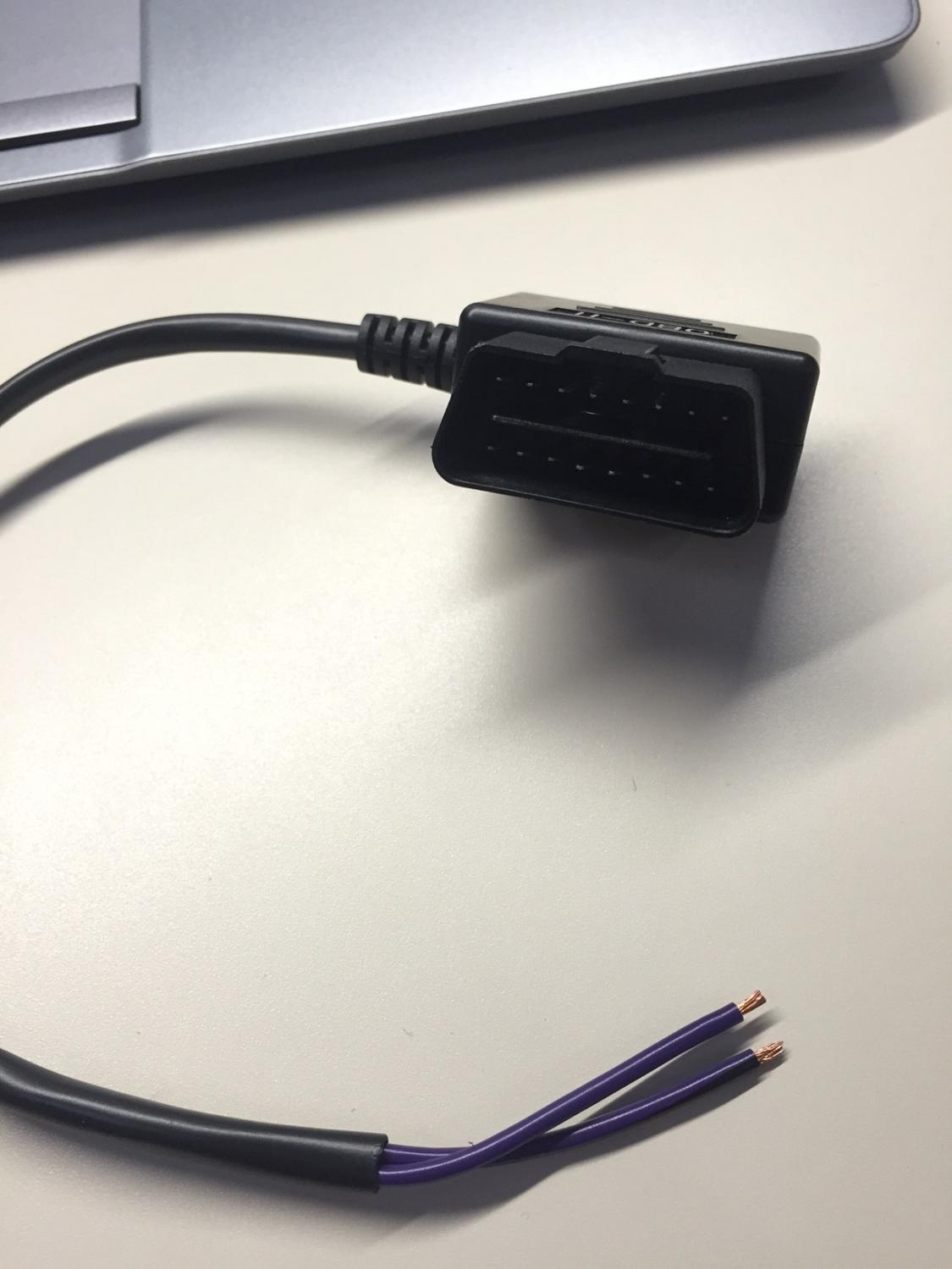
Installation of Amp Research Power Steps on ... - RAM FORUM Engine. 6.7L Diesel. Has anyone installed Amp Research Power Steps themselves on a 5th gen 2500? I have the two purple trigger wires pulled in through the firewall into the cab. Those go to the matching two purplw wires on the supplied OBD interface plug. However, there is a two wire plug coming off that OBD interface plug that they say to plug ... Jayco Wiring Schematic - Wiring Diagram Feb 12, 2019 · Collection of travel trailer wiring schematic. A wiring diagram is a simplified traditional photographic depiction of an electrical circuit. 7 way trailer plug wiring diagram ford awesome 163 best automotive from 2004 ford 7 pin trailer wiring diagram. Rv wiring diagram white board diagram. Each circuit displays a distinctive voltage condition. Online Wiring Informa on - Winnebago The “Blue” labeled 15‐amp. circuit breaker in the 120‐volt load center is providing power to this romex. The romex is 17,000 mm long (divide 17,000 by 25.4 = 669.29 inches). Arrows indicate the power flow away from the load center (beneficial for proper wiring of GFCI outlets). How to Install Amp Research PowerStep ... - ExtremeTerrain.com Fasten loosely to allow for adjustments. Step 8: Line up rear of step extrusion with rear fender well. Step 9: Tighten 4 socket cap screws with 3/16" allen wrench. Torque to 10 ft.-lbs. Step 10: Remove fuse from Power Step wire harness. Step 11: Install controller on passenger side at firewall.
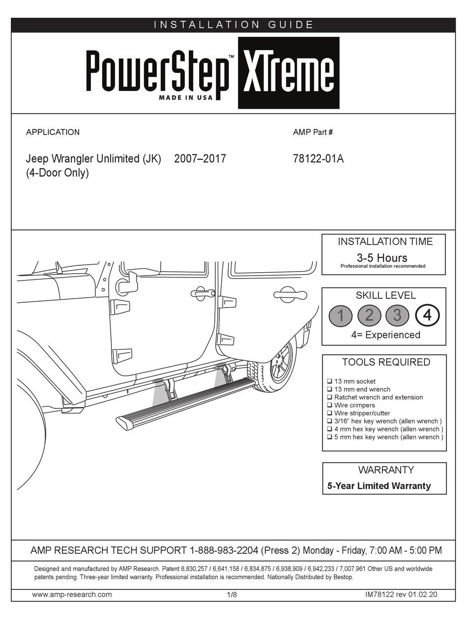
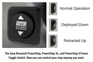
AMP RESEARCH POWERSTEP XTREME 78122-01A INSTALLATION MANUAL ...
AMP Power Steps Wiring - Toyota Tundra Forum I am installing a set of AMP Power Steps and am having trouble with the wiring. The white and blue activation wires are tough to get up thru the floor on the driver side so I thought I would wire just the Passenger side. I found the Tan and Green wires as advertised. I hooked the white wire to the Tan wire and the blue wire to the green wire.

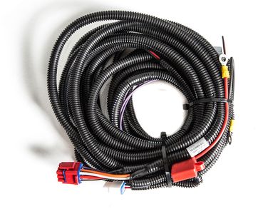
Amp Power Step Install Kit
PDF TALLAT DE - AMP Research Remove power fuse. Attach power lead (RED wire) to positive pole on the battery. CAUTION: Do not ground wrench when engaged Attach ground lead to negative battery pole. Slide mounting T-nut into position, aligning the end of the board with the rear edge of the back door.
AMP Research Power Step | RealTruck
Amp Research Power Step Wiring ... - Wiring Diagram Sample Please download these amp research power step wiring diagram by using the download button, or right select selected image, then use Save Image menu. Wiring diagrams help technicians to find out what sort of controls are wired to the system. Many people can understand and understand schematics referred to as label or line diagrams.
AMP Research 76404-01A PowerStep Plug N Play Pass Thru Harness for All Applicable Models (Except Ram, Toyota) , Black
PDF AMP RESEARCH POWER STEP - CARiD.com Push both wires through hole. (See Step 20 for passenger side notes.) Plug wire harness into motors. 24 Remove power fuse. Attach power lead RED wire to positive lead in the junction box. CAUTION: Do not ground wrench when engaged with nut. Attach ground lead to junction box mount- ing bracket.
Well this project took way too long - Amp Powersteps | Jeep ...
Amp Research Power Step Wiring Diagram Collection of amp research power step wiring diagram. A wiring diagram is a simplified traditional photographic representation of an electric circuit. It shows the components of the circuit as simplified forms, and the power as well as signal links between the devices.
Just bought amp research power steps.... | Jeep Wrangler Forum
How to Install a 50 amp RV Outlet ... - Electric Problems Get your wiring accessories out! One 50 amp outlet (or NEMA 14-50R), a wire (#6 or six-gauge is highly recommended), and a weather-resistant box. Also, take out your installation tools. Step #2. Safety First! Turn OFF your main power source. Step #3. Finding a place. If you don’t have vacant slots in your breaker panel, you may need to call ...
Help...electrical issue | Jeep Gladiator Forum ...
How to Add an Amplifier To Your Factory Car Stereo System ... If you are installing a subwoofer be sure to verify you have enough room to mount the sub box once you install the sub into it. Be sure to have your wiring diagram for your vehicle ready to refer to. After you’ve verified these things start on the first step below: How to Install 4 Channel Amplifiers Into Your Factory System
OEM Power Fold Running Boards installed on a XLT - Ford F150 ...
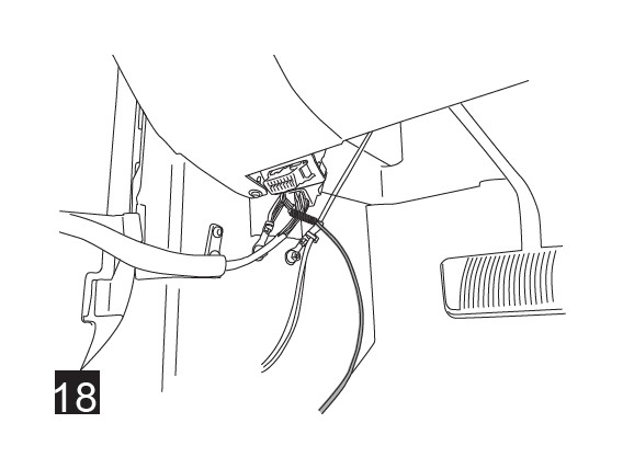
PDF GMT900 PS InstallGuide2009 LK - ElectricStep AMP Research ... AMP RESEARCH POWER STEP - CHEVROLET / GMC 4 4 18 Feed longer wire of Step 15 through tube into door and pull out plastic tube on door side. Route wire along harness to switchplate. Brown plug 4 Locate the brown plug in doors and using supplied Posi-Tap™ connector, splice into trigger wire.

Power Step Running Boards by AMP Research, PowerSteps for Trucks
Amp research power step XL The instructions tell you to mount the Power Step Controller between the battery and passenger side fender - this is a good location to control heat exposure to the controller. Unfortunately, with controller mounted in this location, the wiring harness leg to the driver side is ~12" too short.

Amazon.com: AMP Research 76404-01A PowerStep Plug N Play Pass ...
Hard wiring an Amp running board system? - IGOTACUMMINS You will need to branch the two wires that you have into four, and add a diode to each leg of the branch. The diode part number is 1N4001 that you would need to purchase, and you will need four of these.
MY2022 and Amp Research Powersteps - Ford Truck Enthusiasts ...
Staircase Wiring Circuit Diagram - How to Control a lamp ... In today basic electrical wiring installation tutorial, we will discuss step by step method of staircase wiring installation by using 2-way switches (SPDT = Single Pole Double Through Switch). Also, the same wiring circuit diagram can be used for 2-way lighting or controlling electrical appliances from two different places by using two-way switches.
Delorean Efi Wiring - Amp Research Step Wiring Diagram ...
How to Add a Subpanel (with Pictures) - wikiHow Nov 21, 2019 · Turn off the power to the main panel. Before you begin any work on an electrical panel, shut off all of the power running through it. That way you can’t accidentally shock or electrocute yourself. Look for the main power switch and push it. All of the lights and electrical devices should then turn off.

AMP Research PowerStep Plug N' Play Conversion Kit | 13-15 Ram 1500/2500/3500
PDF H2 PS InstallGuide - ElectricStep AMP Research PowerStep ... AMP RESEARCH POWER STEP - HUMMER H2 Pop off the threshold cover with screw driver and remove the kick panel. Pull up the carpet and thread purple wire through the floor panel (same steps on passenger side except drill through metal grommet with 9/32" bit). Seal wire and grommet with silicone sealer. Cover with tape to prevent sticking to carpet.
AMP Power steps - Page 2 - Ford Truck Enthusiasts Forums
Phasor Diagram Creator Online - Wiring Diagrams B22cs30sns Wiring Diagram; Nissan D21 Fuel Pump Wiring Diagram; Suzuki Gv700 Motorcycle Cdi Wiring Diagram; General Electronic Typical Wiring Diagram Np 26687d; Maestro Ms-ops5m 3way Wiring Diagram; Generac 200 Amp Transfer Switch Wiring Diagram; Clipsal Rj45 Cat6 Wiring Diagram; 2007 Toyota Sienna Fuse Box Diagram; Rki Gd-k77dg Wiring Diagram ...
AMP Research Running Boards Installation Instructions | Manualzz
PDF INSTALLATION TIME SKILL LEVEL 1 2 3 4 - Quadratec.com Route the two Wire Harness legs down over the wheel wells toward Motor Linkages, long leg across to the driver side. Secure harness with tie wraps. Splice Power Step trigger wires into the Door Ajar wires with provided Posi-TapTM splicers. The Power Step trigger wires color coordinate with the factory Door Ajar wires.

2015-2016 F150 Amp Research PowerStep Plug-N-Play Conversion Kit Review & Install
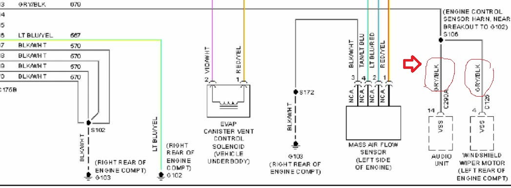
PDF F250 PS InstallGuide & Wiring - CatalogRack Passenger-side wiring Driver-side wiring 1. Remove front kick panel and locate bundle of wires leaving front door just above e-brake assembly (Area-A). Open bundle and locate 18Ga door-ajar wire (yellow with black stripe).

How To Install AMP Research Power Steps: Off-Road.com
Star Delta Starter - (Y-Δ) Starter Power, Control & Wiring ... Automatic Star / Delta Starter with Timer for 3-Phase AC Motors. In this tutorial, we will show the Star-Delta (Y-Δ) 3-phase induction AC Motor Starting Method by Automatic star-delta starter with Timer with schematic, power, control and wiring diagram as well as how star-delta starter works and their applications with advantages and disadvantages.
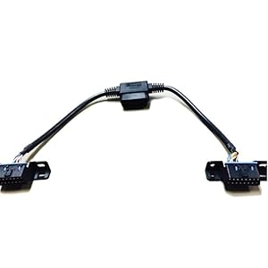
( STA ) 19-04280-STA Controller | A-04 / A-06 Replacement
Amp Power Step Wiring Diagram Gallery - Wiring Diagram Sample amp power step wiring diagram - What's Wiring Diagram? A wiring diagram is a type of schematic which uses abstract pictorial symbols to show all of the interconnections of components in a very system.
Installing Factory Power Running Boards - Ford F150 Forum ...
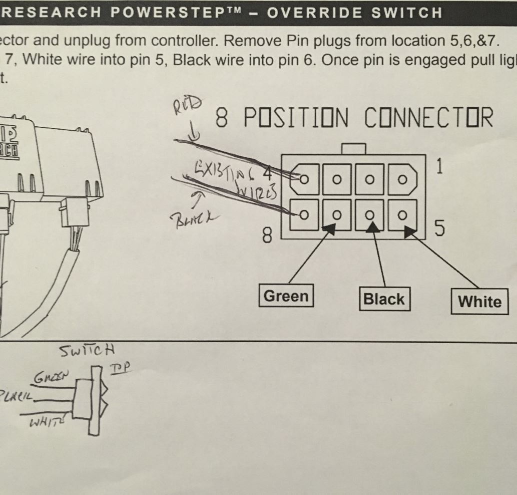
Amp research powerstep switch install The switch has 3 pins - pin 1 goes to a permanent ground wire I attached to one of the grounding bolts by the kick panel area, pin 2 goes to the purple power step wire, and pin 3 goes back to the tapped wire on the door harness. Buying a pack of positaps to add the new wiring will make this project much easier for you.

Install Video: AMP Research PowerStep 2007-2018 Jeep Wrangler JK / JL
Trouble Shooting Guide - FlipHTML5 Trouble Shooting Guide - AMP Research Power Step Table Of ... Factory door ajar switch in-op? Fuse burned Diodes connected in reverse polarity or faulty diode Connections not secure Steps inoperative. Category: All.
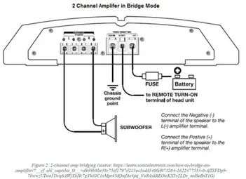
How to bridge an amp and amp wiring diagram. Detailed Guide ...
AMP Research XL Steps 2021 Wiring AMP Research XL Steps 2021 Wiring. Thread starter levessh; Start date Jan 3, 2021; levessh New Member. Joined Jul 23, 2020 Messages 2 Reaction score 0 Location Charlotte Vehicle(s) 2021 JL Wrangler High Altitude Jan 3, 2021. Thread starter #1 I wanted to see if anyone had install the XL steps on their 2021 4 door? There was a wiring change in ...

Install Guide: AMP Research Power Steps on our 2012 F150 ...
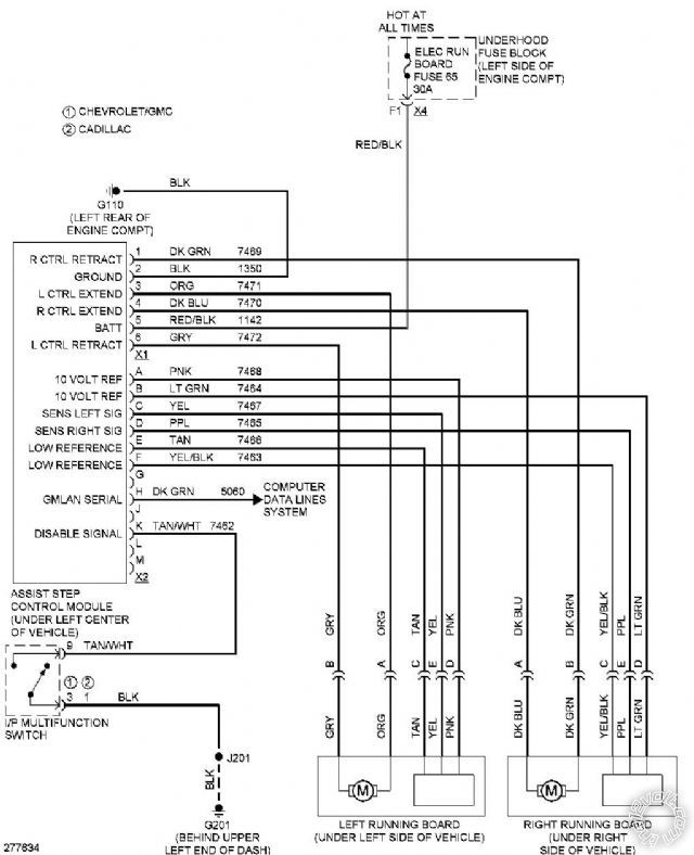
How to Install Amp Research PowerStep ... - AmericanTrucks Locate the vehicle's Door Ajar Switch wires on the removed connector as indicated in chart and diagram below according to vehicle model year. Splice Power Step trigger wires into the Door Ajar wires with provided Posi-TapTM splicers. The Power Step trigger wires color coordinate with the factory Door Ajar wires.

How To Install Amp Research Power Steps | DODGE RAM FORUM ...
Harness Amp Research Power Step ... - Schematicts & Diagram 1. Energy Off Make sure the power is off at the breaker before you start and use a voltage tester to verify that cables and/or electrical connections are completely dead before you start working on them. Make sure everyone in your home is aware that electrical work is going on. Tape the circuit breaker into the off position. 2.

HOW TO DO THE WIRING FOR THE FRONT DRIVER'S SIDE DOOR of the AMP RESEARCH POWERSTEP RUNNING BOARDS
PDF INSTALLATION TIME SKILL LEVEL 1 2 3 4 - AMP Research Loosely loop tie-wraps around large bundle of wires behind battery in engine compartment. Insert controller into tie-wrap loops and cinch down securely. The tie-wraps should cinch down into channels on controller surface. Connect power leads from Controller, Red to positive battery terminal and Black to the vehicle body ground as shown.

How to Install a Car Amp (with Pictures) - wikiHow
Looking for wiring diagram pictures of the AMP power step Can anyone give me info or pictures of the wiring of the AMP power step in the passenger kick panel for a 2020 Gladitor The install directions are useless. thanks frank
AMP RESEARCH POWER STEP INSTALLATION MANUAL Pdf Download ...
PDF TM - AMP Research 2004 model shown Some previous year models require that the ORANGE and WHITE wires be reversed (See wire diagram) Plug in (both sides) 3 2 Open doors to extend arm (if not already extended) TORQUE 10 ft-lbs (13.5 N m) 2 1 10 Attach step Slide mounting T-nut into position 27" 65"
Just bought amp research power steps.... | Jeep Wrangler Forum
Help...electrical issue | Jeep Gladiator Forum ...

Jeep JL Wrangler Amp Research Powerstep Install on a 2019 ...

Ford Super Duty Amp Research Power Step Install
AMP Research side steps on 2018 Tundra | Toyota Tundra Forum
AMP Research Running Boards Installation Instructions
AMP RESEARCH POWER STEP INSTALLATION MANUAL Pdf Download ...
timed 12v relay for power folding steps
How to Install Amp Research PowerStep Xtreme Running Boards ...

AMP Research Power Step running boards - black (09-19 RAM ...
How to Install Amp Research PowerStep on your Wrangler ...
How to Install Amp Research PowerStep on your Wrangler ...

AMP Research Power Step Running Boards
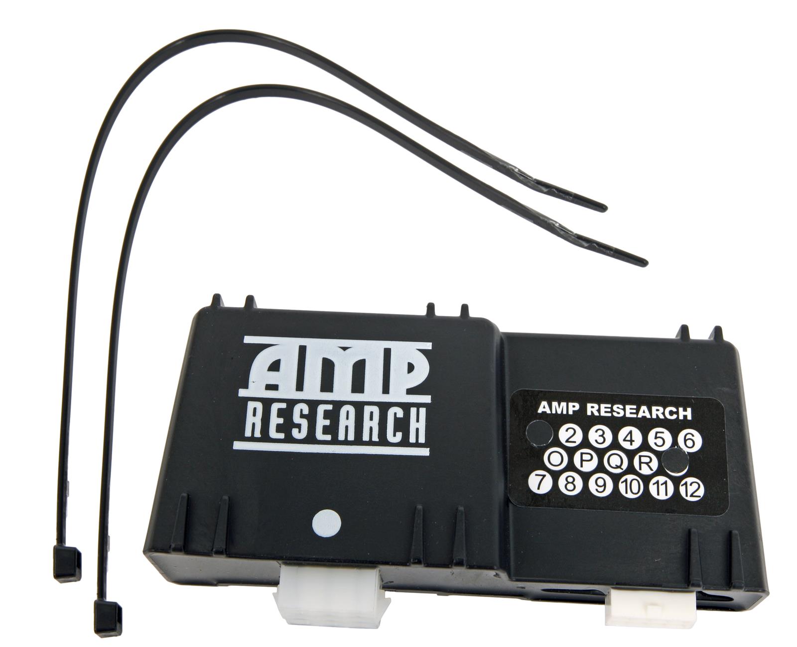
AMP Research 19-04280-STA AMP Research Replacement Controllers | Summit Racing
Kwikee Power Step Problem - Jayco RV Owners Forum
AMP Research PowerStep 2015 Install - 2014 - 2019 Silverado ...


Comments
Post a Comment